REVIEW 4 major objections 5 minor 15 references
Liquid Crystal-Based RIS Loss-Trade-Off Analysis
T0 review · 4 major / 5 minor · reviewed 2026-08-05 · deepseek-v4-flash
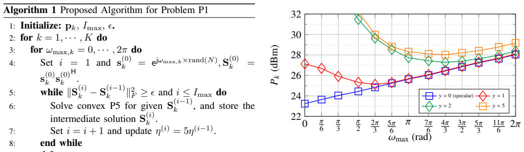
Pith's one-line read The paper claims that the optimal LC-RIS phase-shift range depends on user placement, with specular users best served by near-zero phase range and minimal loss.
desk verdict Useful system-level quantification of the LC phase-range/loss trade-off, but the central figure has a numeric inconsistency that needs checking before design use. read the letter →
The pith
A machine-rendered reading of the paper's core claim, the machinery that carries it, and where it could break.
The reading
What carries the argument
The load-bearing identity is the linear loss–phase-range relation |Ω|²_dB = (2π/FoM)(l/lr) = ωmax/FoM, which makes insertion loss in dB literally proportional to maximum phase-shift range. This is combined with a near-field LOS channel model and an alternating-optimization algorithm: maximum-ratio-transmission beamforming for fixed phases, and a rank-one semidefinite relaxation with a penalty method to set phases for fixed ωmax, followed by a grid search over ωmax.
What would settle it
Measure the insertion loss of a fabricated LC delay-line phase shifter at 28 GHz for several lengths and across the full tuning range. If the loss per element includes a fixed overhead (so dB loss versus length has a positive intercept) or if the figure of merit varies with tuning state, recompute the required transmit power versus ωmax; an interior optimum may vanish or move to a different ωmax.
Extended reading notes
Core claim
The paper models an LC-RIS where the maximum phase-shift range is Δωmax = 2πl/lr and the insertion loss in dB is |Ω|²_dB = (2π/FoM)(l/lr), making loss in dB proportional to the maximum phase-shift range. Optimizing beamforming and RIS phases to minimize transmit power subject to an SNR constraint, the paper finds an interior optimum for off-specular users: the SNR benefit of a wider phase range is eventually outweighed by the insertion-loss penalty. For specular users the optimum is at ωmax = 0. The claimed conclusion is that there exists an LC phase-shifter length achieving a scenario-dependent optimal trade-off, with the optimal ωmax increasing as users move away from the specular directio
Load-bearing premise
The central result rests on the assumption that insertion loss in dB is exactly proportional to LC phase-shifter length (constant figure of merit), with no fixed overhead loss or state-dependent variation; if that linearity fails, the optima can shift or disappear.
Editorial extensions
If this is right
- Full 2π phase range is not universally optimal; in specular-rich deployments, a minimal-range LC-RIS with low loss can meet quality-of-service at lower transmit power.
- Off-specular users impose a larger optimal ωmax, so user geometry should inform LC phase-shifter length selection.
- Larger coverage areas raise both the required transmit power and the optimal ωmax, indicating that wide-coverage LC-RIS design needs longer, lossier shifters.
- The optimal ωmax increases with figure of merit for off-specular users, so improvements in LC material quality relax the loss penalty.
- In a TDMA system with a shared fixed-length RIS, the optimal length depends on the hardest-to-steer user, not on the average user.
Reading between the lines
- If the linear-loss model holds, the optimal phase range for a given user distribution could be derived from the angular spread of coverage, suggesting a design rule: choose LC length to cover the widest required steering angle plus margin, and no more.
- Since a single LC-RIS length is shared across users in TDMA, deployments with mixed specular and off-specular users might benefit from segmented RIS designs where different regions of the surface have different phase-shift ranges.
- A testable extension is to measure required transmit power versus ωmax on a fabricated LC-RIS and verify the interior optimum and its dependence on the figure of merit.
- The trade-off likely persists with non-line-of-sight components, but multipath may reduce the need for large phase ranges because diffuse reflections provide incidental coverage, lowering the optimal ωmax.
Signed reviews
Editorial analysis
A structured set of objections, weighed in public.
Referee Report
Summary. This paper studies the trade-off between insertion loss and phase-shift range in liquid-crystal-based reconfigurable intelligent surfaces (LC-RIS). The authors model a delay-line LC phase shifter whose maximum phase shift and insertion loss both increase linearly with physical length (Eqs. (6) and (8)). For a narrow-band downlink system with blocked direct links, they formulate a transmit-power minimization problem under a per-user SNR constraint and a phase-range constraint, solve it by alternating optimization between beamforming and RIS phases, and simulate the required power versus ω_max for users at different locations and coverage radii. The central claim is that an interior optimal LC phase-shifter length exists and depends on user location and coverage area, so designing for full 2π range is not always optimal.
Significance. If the numerical results are accurate, the paper provides a useful design insight for LC-RIS hardware: the optimal phase-shifter length depends on the deployment scenario, and a smaller-than-2π range can be beneficial in specular-rich settings. The paper contributes a complete optimization formulation, a numerical algorithm, and parametric studies using a measured FoM from the authors' own device. However, the existence of the trade-off is largely a consequence of the assumed linear loss model, and the quantitative conclusions rest on simulation curves that currently show a discrepancy with the stated model. The work is therefore a promising co-design study rather than a demonstration of a new fundamental principle.
major comments (4)
- [§V.B, Fig. 2] The specular-user (y=0) curve is inconsistent with the loss model in §III. With FoM=75°/dB, Eq. (8) gives |Ω|²_dB = (2π/FoM)(l/l_r) = ω_max/(75π/180), so the required power for the specular user should increase by exactly 4.8 dB between ω_max=0 and 2π. The plotted rise appears to be about 7–8 dB. Since this curve is the baseline against which off-specular optima are measured, please provide the exact simulation parameters, correct the plot, or explain the discrepancy (e.g., a different FoM, additional loss, or suboptimal phase recovery).
- [§IV, Algorithm 1] After solving P5, the algorithm selects [S_k*, ω_max,k*] but never recovers the phase vector s_k from S_k* before computing q_k with Eq. (11). If S_k* is only approximately rank-one, the reported P_k may not correspond to a feasible RIS configuration. Please add an explicit rank-one recovery step (e.g., principal eigenvector) and state how the recovered s_k satisfies the phase-range constraint.
- [§IV, Eq. (15)] The convex reformulation cC2 is imported from [14, Lemma 2 and Lemma 3] without stating the lemmas or providing a proof/sketch. This reformulation is central to the convex problem P5 and hence to all numerical results. The paper should either prove the reformulation in an appendix or state the lemmas explicitly. The equation as typeset is also garbled, with missing quantifiers and misaligned branches.
- [§III and §I] The headline 'fundamental trade-off' is not an independent discovery: combining Eqs. (6) and (8) gives |Ω|²_dB = ω_max/FoM, so loss in dB is proportional to ω_max by construction. The existence of an interior optimum for off-specular users follows whenever the SNR gain from increased phase range saturates. The paper should present the contribution as a quantitative evaluation of this model-dependent trade-off, not as a new fundamental phenomenon, and should state the linear-loss assumption explicitly as a modeling simplification.
minor comments (5)
- [§III, Eqs. (7)–(8)] Please make the units of FoM explicit. The text quotes FoM as 75°/dB, but Eq. (8) uses 2π in the numerator; the equation is only correct if FoM is converted to rad/dB or if ω_max is expressed in degrees consistently.
- [§IV, Algorithm 1 line 3] The loop 'for ω_max,k = 0, · · ·, 2π' should state the step size or grid (|W|). The complexity expression includes |W| but the discretization is not specified in the algorithm.
- [§II.A and §IV] The symbol P_k is used both for the coverage area set (possible user locations) and for the transmit power variable. This is confusing; please rename one of them.
- [§V.B, Figs. 2 and 4] The FoM value used in the simulations is stated only in the text around Fig. 2; the figure captions should include it for reproducibility. Similarly, the path-loss and noise parameters are in the text but not in the captions.
- [§VI, Conclusion] The conclusion mentions a 'simplified scenario' but does not list which simplifications are most consequential (LOS-only channels, constant FoM, maximum-loss-at-all-phase-states, no fixed overhead losses). A short limitations paragraph would help readers judge practical applicability.
Circularity Check
No significant circularity; the central trade-off is computed from an explicit loss model and optimization, with only minor self-citations for measured parameters.
full rationale
The paper's headline trade-off is not circular. The loss-phase relation in Section III is transparently derived: Eq. (6) sets Δωmax = 2π l/lr and Eq. (8) sets |Ω|²_dB = (2π/FoM)(l/lr), so for a constant FoM the loss in dB is proportional to the phase-shift range. This is an explicit modeling assumption, not a hidden equivalence between a 'prediction' and an input. The system-level result — that an interior optimal phase-shifter length exists for off-specular users — is obtained by numerically solving the non-convex power-minimization problem (P1–P5) over a sweep of ωmax values, not by fitting a parameter to a target curve. The optimal lengths in Figs. 2–4 are outputs of the optimization, not re-statements of the loss model alone; the geometry of the user locations determines whether the steering benefit outweighs the loss. The FoM = 75°/dB is taken from the authors' own measured device [12], a self-citation, but it is a measured physical parameter rather than a fitted prediction, and the main qualitative claim (scenario-dependent optimal length) is robust to the FoM value — indeed Fig. 3 parametrically varies FoM. The convexification lemmas from [14] are mathematical tools, not a uniqueness theorem invoked to forbid alternatives. The potential discrepancy in Fig. 2's specular-user slope (expected ~4.8 dB under the stated FoM) is a quantitative reproducibility concern that should be checked, but it is not a demonstration that the derivation reduces to its inputs. No circular step of the enumerated kinds is present; only minor non-load-bearing self-citations exist.
Assumptions & free parameters
free parameters (1)
- FoM (figure of merit of the LC phase shifter) =
75°/dB at 28 GHz (ref. [12])
assumptions (6)
- domain assumption Loss is linear in shifter length at constant FoM: |Ω|²_dB = (2π/FoM)(l/lr) (Eq. 8), with FoM constant over tuning range, frequency, and all elements.
- domain assumption Maximum phase shift is linear in length: Δωmax = 2π l/lr (Eq. 6).
- domain assumption The sector constraint convexification cC2 (Eq. 15) from [14, Lemmas 2-3] is correct for both ωmax > π and ωmax ≤ π.
- standard math MRT is the optimal beamformer for the per-slot single-user problem (Eq. 11).
- domain assumption Channels are treated as pure LOS (H ≈ H_LOS) even though the setup declares Rician K = 10, and direct BS-MU paths are blocked.
- standard math Penalty method equivalence: for sufficiently large η, P4 and P5 are equivalent (Eq. 16).
Cite this review
Pith. "Pith review of Liquid Crystal-Based RIS Loss-Trade-Off Analysis." pith.science (2026). https://pith.science/paper/EUL34NS5
@misc{pith2026250811489,
  author       = {Pith},
  title        = {Pith review of: Liquid Crystal-Based RIS Loss-Trade-Off Analysis},
  year         = {2026},
  howpublished = {\url{https://pith.science/paper/EUL34NS5}},
  note         = {Machine review of arXiv:2508.11489}
}
read the original abstract
Liquid crystal (LC) technology has emerged as a promising solution for large reconfigurable intelligent surfaces (RISs) at millimeter wave (mmWave) bands, offering advantages such as low power consumption, scalability, and continuously tunable phase shifts. For LC-RIS based on the delay-line architecture, i.e., with dedicated phase shifters, there exists a trade-off between the maximum achievable phase-shift range and the corresponding insertion loss, which has not been studied for LC-RIS-assisted wireless systems yet. In this paper, we investigate this trade-off where a base station (BS) and an RIS are configured to minimize the transmit power while satisfying a given quality of service (QoS) for a number of users. Simulation results reveal a fundamental trade-off between the total transmit power and the achievable data rate as a function of the LC phase-shift range.
Figures


Figures from the paper (1 more)

Reference graph
Works this paper leans on
-
[1]
A. Jiménez-Sáez et al., “Reconfigurable intelligent surfaces with liquid crystal technology: A hardware design and communication perspective,” preprint arXiv:2308.03065, 2023
arXiv 2023
-
[2]
R. Jakoby, A. Gaebler, and C. Weickhmann, “Microwave liquid crystal enabling technology for electronically steerable antennas in satcom and 5G millimeter-wave systems,” Crystals, vol. 10, no. 6, p. 514, 2020
work page 2020
-
[3]
Architecture for sub-100 ms liquid crystal reconfigurable intelligent surface based on defected delay lines,
R. Neuder, M. Späth, M. Schüßler, and A. Jiménez-Sáez, “Architecture for sub-100 ms liquid crystal reconfigurable intelligent surface based on defected delay lines,” Commun. Eng., vol. 3, no. 1, p. 70, 2024
2024
-
[4]
Reconfigurable intelligent surfaces for energy effi- ciency in wireless communication,
C. Huang et al. , “Reconfigurable intelligent surfaces for energy effi- ciency in wireless communication,” IEEE Trans. Wireless Commun. , vol. 18, no. 8, pp. 4157–4170, 2019
work page 2019
-
[5]
W. Tang et al., “Wireless communications with reconfigurable intelligent surface: Path loss modeling and experimental measurement,” IEEE Trans. Wireless Commun., vol. 20, no. 1, pp. 421–439, 2021
work page 2021
-
[6]
Phase dependent loss analysis for RIS systems,
I. Singh, P. J. Smith, and P. A. Dmochowski, “Phase dependent loss analysis for RIS systems,” in Proc. IEEE Wireless Commun. and Netw. Conf. (WCNC), 2023, pp. 1–6
work page 2023
-
[7]
Design of a power amplifying-ris for free- space optical communication systems,
A. R. Ndjiongue et al. , “Design of a power amplifying-ris for free- space optical communication systems,” IEEE Wireless Communications, vol. 28, no. 6, pp. 152–159, 2021
work page 2021
-
[8]
Fast Reconfiguration of Liquid Crystal-RISs: Modeling and Algorithm Design
M. Delbari, R. Neuder, A. Jiménez-Sáez, A. Asadi, and V . Jamali, “Fast reconfiguration of LC-RISs: Modeling and algorithm design,” arXiv preprint arXiv:2504.08352, 2025
work page Pith review arXiv 2025
Show all 15 references
-
[9]
Near-field multipath MIMO channel model for imperfect surface reflection,
M. Delbari, G. C. Alexandropoulos, R. Schober, H. V . Poor, and V . Jamali, “Near-field multipath MIMO channel model for imperfect surface reflection,” in IEEE Globecom Workshops (GC Wkshps) , 2024
2024
-
[10]
Fast transition-aware reconfiguration of liquid crystal- based RISs,
M. Delbari et al., “Fast transition-aware reconfiguration of liquid crystal- based RISs,” in Proc. IEEE ICC Workshops , 2024, pp. 214–219
2024
-
[11]
Far- versus Near-Field RIS Modeling and Beam Design,
M. Delbari, G. C. Alexandropoulos, R. Schober, and V . Jamali, “Far- versus Near-Field RIS Modeling and Beam Design,” in Re- configurable Metasurfaces for Wireless Communications: Architec- tures, Modeling, and Optimization . Springer, 2024, arXiv preprint: https://arxiv.org/p...
2024 arXiv
-
[12]
Compact liquid crystal-based defective ground struc- ture phase shifter for reconfigurable intelligent surfaces,
R. Neuder et al., “Compact liquid crystal-based defective ground struc- ture phase shifter for reconfigurable intelligent surfaces,” in European Conf. Antennas and Propag. (EuCAP) , 2023, pp. 1–5
2023
-
[13]
Fundamentals of wireless communication,
D. Tse, “Fundamentals of wireless communication,” Cambridge Univer- sity Press google schola , vol. 2, pp. 614–624, 2005
2005
-
[14]
Temperature-aware phase-shift design of LC-RIS for secure communication,
M. Delbari et al., “Temperature-aware phase-shift design of LC-RIS for secure communication,” in Proc. IEEE ICC , 2025, arXiv:2411.12342
2025
-
[15]
Power-efficient resource allocation for multiuser miso systems via intelligent reflecting surfaces,
X. Yu et al. , “Power-efficient resource allocation for multiuser miso systems via intelligent reflecting surfaces,” in IEEE Global Commun. Conf. (GLOBECOM), 2020, pp. 1–6
2020
Reviewed August 5, 2026 · model on record in the stance chip above.
Discussion (0). Continue with ORCID to comment.