REVIEW 4 major objections 6 minor 22 references
LinkBo: An Adaptive Single-Wire, Low-Latency, and Fault-Tolerant Communications Interface for Variable-Distance Chip-to-Chip Systems
T0 review · 4 major / 6 minor · reviewed 2026-08-05 · deepseek-v4-flash
Pith's one-line read LinkBo claims a single wire can deliver an acknowledged, CRC-checked high-priority message in 50.4 µs, at least 20X faster than the 1-wire protocol and 6.3X faster than UNI/O, by encoding sync, priority, and clock recovery into a two-slot M
desk verdict The 50.4 µs latency is real for a quiet bus, but the 'hardware interrupt' and the 15 m/7.5 Mbps claims are not backed by the experiments. read the letter →
The pith
A machine-rendered reading of the paper's core claim, the machinery that carries it, and where it could break.
The reading
What carries the argument
The synchronization field is the load-bearing object. It consists of two Manchester slots whose low-pulse pattern distinguishes message priority and whose measured duration — counted by a prescaler from the first falling edge — recovers the transmitter's bit-slot time in the receiver's clock domain. That single measurement sets every subsequent decode; the re-synchronization module then keeps mid-slot edges aligned, and the 4-bit CRC plus ACK edge closes the loop with positive error feedback. The HP sync's three-times-longer low pulse is also what makes high-priority messages reach 15 m while low-priority messages fail past 5.6 m.
What would settle it
Re-run the two-FPGA demonstration while sweeping wire length in half-meter steps from 5 m to 24 m at the 3 MHz clock, and also inject a spurious edge just before the sync edge at the receiver pin. The paper's argument predicts LP messages cease between 5.6 and 9 m and HP messages between 15 and 23 m, and that any ambiguity in the very first low pulse corrupts the frame: a mismatch in the cliff locations or a recovered message after an early spurious edge would overturn the synchronization claim.
Extended reading notes
Core claim
LinkBo is a half-duplex single-wire protocol using IEEE802.3 Manchester encoding, so data, clock, and acknowledgment share one pin. Messages start with a two-slot synchronization field that also tags priority: a low first slot marks a high-priority message, a high first slot a low-priority one. The receiver's prescaler counts the first low pulse and divides by 1.5 to recover the transmitter's slot time, so the chips need no shared clock. A 4-bit CRC plus a no-edge/edge ACK gives the sender positive confirmation of a valid frame. On two FPGAs joined by one wire, the paper reports a 50.4 µs end-to-end high-priority message — 20X faster than 1-wire, 6.3X faster than UNI/O — and adaptive operati
Load-bearing premise
The receiver locks onto a message by measuring the first low pulse on the wire and deriving the bit time from that one measurement; if the first falling edge is missed or blurred by wire effects, the entire message is lost before any error check can run.
Editorial extensions
If this is right
- Interrupt-class messages can be acknowledged and CRC-checked end-to-end in 50.4 µs, making single-wire links viable for time-critical traffic that previously required multi-wire buses.
- A single wire now spans the distance range that matters for board-level design — centimeters on a PCB up to tens of meters between boards — by trading bit rate for reach (7.5 Mbps at 11 cm, 300 kbps at 15 m).
- Because CRC and ACK are built into every frame, a receiver can silently drop corrupted messages and the sender learns of failure, closing a robustness gap the paper identifies in 1-wire and UNI/O.
- The protocol's peer-to-peer wiring with wired-AND arbitration and a repurposable size field gives a route to multi-drop busses without a dedicated host, removing the single point of failure in 1-wire's master/slave model.
Reading between the lines
- The sync-pulse length is the real dial between speed and reach: the paper effectively samples only two settings (a one-slot low for LP, a three-times-longer low for HP), so an intermediate sync length might extend LP-class messages well beyond 5.6 m at a modest latency cost — an axis the paper leaves unmapped.
- If the single-edge sync assumption is the weak point, a multi-edge or averaging sync (for example measuring both the first low pulse and the following half-slot) could make the protocol immune to a missed or glitched first edge without changing the frame format.
- The wired-AND arbitration is only sketched; an interesting test the paper does not run is arbitration between simultaneous LP and HP sync patterns, where the winner's sync is already partly distorted before the loser stops driving.
Editorial analysis
A structured set of objections, weighed in public.
Referee Report
Summary. The paper proposes LinkBo, a single-wire, Manchester-coded chip-to-chip protocol with two message priorities, a 4-bit CRC, acknowledgment, and a hardware-interrupt mechanism for high-priority (HP) messages. The authors present a Simulink system/channel model, an RTL-style architecture for TX/RX/driver, and an FPGA implementation on two Cyclone-IV boards. Measured results include a 50.4 µs HP latency on an idle 11 cm wire, LP latencies up to 224.4 µs for 7 bytes, HP throughput up to 15 m (300 kbps) and 7.5 Mbps over 11 cm, and LP throughput up to 5.6 m. The paper compares LinkBo against 1-wire and UNI/O in latency, effective bit rate, and distance.
Significance. If the claims are fully validated, LinkBo would be a useful contribution to single-wire interfaces for short-range chip-to-chip links: it offers a concrete message format, CRC/ACK error handling, and a measured latency advantage over commercial 1-wire and UNI/O. The strengths of the paper include a working FPGA demonstration, measurement-based latency and throughput figures, and a parameterized channel model (Section IV-C) that gives quantitative sensitivity trends. However, the headline claims are currently broader than the evidence: the 50.4 µs latency is not shown under bus contention, the 15 m/300 kbps and 7.5 Mbps figures apply only to HP messages, and the hardware-interrupt feature is described but not implemented or tested. These discrepancies need to be resolved before the central claims can be accepted.
major comments (4)
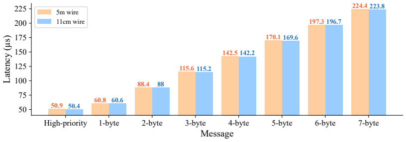
- [Abstract; Section III-B; Section VII-A] The abstract states that 'LinkBo protocol-level guarantees that high-priority messages are delivered ... in just 50.4 µs.' This is not established for the interrupt scenario. Section III-B describes HP messages interrupting LP transmission, and Section V-C introduces the LBDET interrupt trigger, but no contention experiment, timing diagram, or state-machine detail is provided. The 50.4 µs value in Section VII-A and Fig. 14 is measured for a single HP message on an idle bus (11 cm and 5 m, one message type at a time). The abstract should say 'measured on an idle bus' or the authors must add an experiment where an HP message interrupts an ongoing LP transmission and measure the actual delivery latency under that condition.
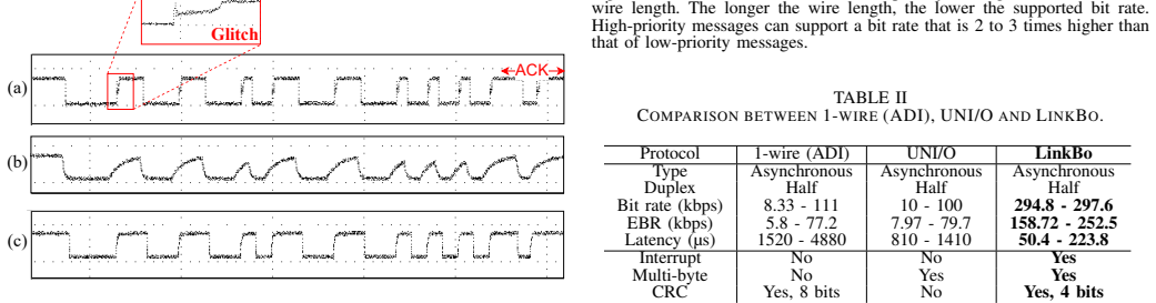
- [Abstract; Section VII-B; Fig. 15; Fig. 17] The abstract's distance and bitrate claims are not qualified by message priority. Fig. 15 shows LP throughput drops to near zero beyond ~5.6 m, while HP throughput persists until ~15 m. Fig. 17 shows 11 cm HP reaches 7.5 Mbps but LP reaches only 2.3 Mbps. Therefore the statement 'reliably supports wire lengths up to 15 meters with a data rate of 300 kbps, while reaching a maximum data rate of 7.5 Mbps over an 11 cm wire' is misleading when read as applying to the protocol generally. These numbers are HP-only. The abstract and Section VII-B must state that the 15 m/300 kbps and 7.5 Mbps figures are for high-priority messages only, and that low-priority messages are limited to 5.6 m and 2.3 Mbps.
- [Section III-B; Section III-C; Section V-C] The hardware-interrupt mechanism is underspecified at the physical layer. In half-duplex operation, a transmitting node is actively driving the bus; it cannot simply 'watch' for a falling-edge HP sync without an explicit collision-detection or abort rule. The paper states LBDET 'watches for prolonged low-level signals' and triggers an interrupt, but does not explain how a transmitting node can observe the bus while driving, how it aborts its own transmission, or how bus turn-around is managed. This is load-bearing for the claimed HP preemption capability. A concrete state diagram, a timing diagram of the interruption sequence, and an experimental demonstration are needed.
- [Section III-C; Section VII-B] The synchronization scheme relies on detecting the first falling edge and measuring the low-pulse duration to distinguish HP from LP messages. The sensitivity of this single-point edge detection is not characterized beyond the distance sweep. The paper's own data show that LP messages (shorter sync low pulse) fail at 5.6 m, while HP messages (three-times-longer low pulse) survive to 15 m. This suggests that the claimed robustness is strongly dependent on the sync-pulse edge being clean. The authors should provide a quantitative analysis of timing margin versus wire length, capacitance, or supply voltage to support the 'fault-tolerant' characterization, or soften the robustness claim to the tested conditions.
minor comments (6)
- [Section I; Fig. 1] The left panel of Fig. 1 appears to show total communication pins for SPI and I2C, but the figure caption is ambiguous; please clarify which line corresponds to SPI and which to I2C, and define 'Total Devices' on the x-axis.
- [Section II-C; Table I] Table I lists 'Speed' ranges for 1-wire and UNI/O, but the LinkBo row is absent from that table; the comparison table in Section VII-C is more complete. Consider consolidating the two tables or adding LinkBo to Table I to avoid confusion.
- [Section III-B; Fig. 5] The text says HP messages use '2 bit slots for synchronization,' but the description of the sync field says the first slot is held low and the second is Manchester 1. Clarify that a Manchester 'slot held low' is not a valid Manchester code; this is intentional for HP detection, but the wording should explain that the HP sync is not Manchester-encoded in the first slot.
- [Section IV-C; Fig. 10] The 'LPF' label in Fig. 10 and Eq. (3) is unclear: the low-pass filter cutoff frequency is computed, but the relationship between LPF condition and throughput drop is not explained. Also, the star marker in Fig. 10 is not defined in the caption.
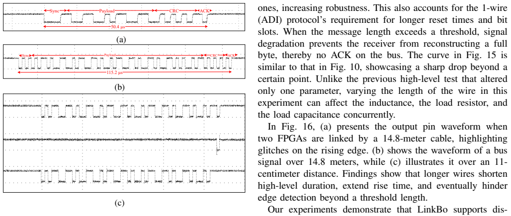
- [Section VII-A; Fig. 14] The figure shows '50.4 µs' for HP on 11 cm, but the text in Section VI says the HP message takes 47.5 µs plus 2.9 µs ACK. The discrepancy is small but should be reconciled, or explicitly state that the 50.4 µs includes ACK time.
- [General] The paper contains several typographical issues: 'thesis' in Section II-B, 'Linkbo' vs 'LinkBo' inconsistency, and missing commas in references. These should be cleaned up.
Circularity Check
No significant circularity: the headline latency and throughput numbers are direct FPGA measurements, and the Simulink sensitivity model is not used to fit or predict those numbers.
full rationale
The central quantitative claims (50.4 us HP latency, 7.5 Mbps max bit rate, 15 m distance) come from oscilloscope measurements on an FPGA testbed (Sec. VI, VII), not from a model that already encodes those results. The Simulink channel model in Sec. IV-C is parameterized with PCB parasitic values and used for a sensitivity analysis (Fig. 10), but the measured latency/throughput results in Sec. VII are not fitted outputs of that model; the model is not used to predict the headline numbers. There are no author self-citations or imported uniqueness theorems; the cited references are external datasheets, standards, and prior works unrelated to the authors. No equation is shown to be equivalent to its own input by construction. The closest vulnerabilities are non-circular: the hardware-interrupt mechanism (Sec. III-B, III-C, V-A) is asserted but not experimentally exercised, and the comparison with 1-wire/UNI/O (Sec. VII-C, Table II) relies on different measurement/specification conditions. These are evidence-completeness and benchmarking-fairness concerns, not circular reductions. Therefore the derivation chain is self-contained with respect to circularity.
Assumptions & free parameters
free parameters (1)
- Operating clock frequency (3 MHz) =
3 MHz (test), PLL up to 100 MHz
assumptions (5)
- standard math Manchester encoding is self-clocking and DC-free, so the receiver can recover the clock from signal transitions.
- standard math The CRC-4 polynomial X^4+X+1 detects single-bit errors and most two-bit errors, and burst errors per Eq. (1).
- domain assumption Multi-device wired-AND arbitration behaves as described in Section III-E.
- domain assumption The Simulink channel model with parasitic R=330 Ohm, C=100 pF, L=50 nH approximates the real wire and PCB.
- domain assumption Receiver edge detection and low-duration measurement are reliable across the claimed wire-length range.
Cite this review
Pith. "Pith review of LinkBo: An Adaptive Single-Wire, Low-Latency, and Fault-Tolerant Communications Interface for Variable-Distance Chip-to-Chip Systems." pith.science (2026). https://pith.science/paper/CZZ4KOCI
@misc{pith2026250901339,
  author       = {Pith},
  title        = {Pith review of: LinkBo: An Adaptive Single-Wire, Low-Latency, and Fault-Tolerant Communications Interface for Variable-Distance Chip-to-Chip Systems},
  year         = {2026},
  howpublished = {\url{https://pith.science/paper/CZZ4KOCI}},
  note         = {Machine review of arXiv:2509.01339}
}
abstract
Cost-effective embedded systems necessitate utilizing the single-wire communication protocol for inter-chip communication, thanks to its reduced pin count in comparison to the multi-wire I2C or SPI protocols. However, current single-wire protocols suffer from increased latency, restricted throughput, and lack of robustness. This paper presents LinkBo, an innovative single-wire protocol that offers reduced latency, enhanced throughput, and greater robustness with hardware-interrupt for variable-distance inter-chip communication. The LinkBo protocol-level guarantees that high-priority messages are delivered with an error detection feature in just 50.4 $\mu$s, surpassing current commercial options, 1-wire and UNI/O by at least 20X and 6.3X, respectively. In addition, we present the hardware architecture for this new protocol and its performance evaluation on a hardware platform consisting of two FPGAs. Our findings demonstrate that the protocol reliably supports wire lengths up to 15 meters with a data rate of 300 kbps, while reaching a maximum data rate of 7.5 Mbps over an 11 cm wire, providing reliable performance for varying inter-chip communication distances.
Figures


Figures from the paper (12 more)



Reference graph
Works this paper leans on
-
[1]
An introduction to i 2 c and spi protocols,
F. Leens, “An introduction to i 2 c and spi protocols,” IEEE Instrumen- tation & Measurement Magazine , vol. 12, no. 1, pp. 8–13, 2009
work page 2009
- [2]
- [3]
-
[4]
Overview of 1-wire technology and its use,
A. D. Inc., “Overview of 1-wire technology and its use,” 2008
work page 2008
-
[5]
Implementing 1-wire enumeration for tmp1826 with tm4c129x microcontrollers,
T. I. Inc., “Implementing 1-wire enumeration for tmp1826 with tm4c129x microcontrollers,” 2018
work page 2018
-
[6]
Encoder circuit for inverse differential manchester code operating at any frequency,
A. Al-Sammak, “Encoder circuit for inverse differential manchester code operating at any frequency,” Electronics Letters , vol. 38, no. 12, p. 1, 2002
work page 2002
- [7]
-
[8]
Stm8 swim communication protocol and debug module,
S. NV , “Stm8 swim communication protocol and debug module,” 2016
work page 2016
Show all 22 references
-
[9]
Monolithic data circuit-terminating unit (dcu) for a one- wire vehicle network,
C. A. dos Reis Filho, E. Da Silva, E. d. L. Azevedo, J. A. Semin ´ario, and L. Dibb, “Monolithic data circuit-terminating unit (dcu) for a one- wire vehicle network,” in Proceedings of the 24th European Solid-State Circuits Conference, pp. 228–231, IEEE, 1998
1998
-
[10]
Design and analysis of an experimental data and clock multiplexing technique for generating faster single wire synchronous data bus,
H. Rahman and M. T. Arefin, “Design and analysis of an experimental data and clock multiplexing technique for generating faster single wire synchronous data bus,” in 2019 2nd International Conference on Innovation in Engineering and Technology (ICIET) , pp. 1–5, IEEE, 2019
2019
-
[11]
Wired-fm, a novel distributed digital single-wire field bus,
H. F. Rezaei and A. Kruger, “Wired-fm, a novel distributed digital single-wire field bus,” in 2012 IEEE International Conference on Elec- tro/Information Technology, pp. 1–4, IEEE, 2012
2012
-
[12]
Simultaneous data transfers over peripheral bus using cdma technique,
T. Nikolic, G. Djordjevic, and M. Stojcev, “Simultaneous data transfers over peripheral bus using cdma technique,” in 2008 26th International Conference on Microelectronics , pp. 437–440, IEEE, 2008
2008
-
[13]
Physical layer architecture for 1-wire sensor communication bus: Binary channel code division multiple access,
B. Peiffer and A. Kruger, “Physical layer architecture for 1-wire sensor communication bus: Binary channel code division multiple access,” in 2011 IEEE Sensors Applications Symposium , pp. 100–105, IEEE, 2011
2011
-
[14]
Low weight double layer coded cdma as a novel physical layer for onewire bus communication in sensor networks,
H. F. Rezaei and A. Kruger, “Low weight double layer coded cdma as a novel physical layer for onewire bus communication in sensor networks,” in 2013 IEEE Sensors Applications Symposium Proceedings , pp. 15–20, IEEE, 2013
2013
-
[15]
Sniffing one-wire algorithm using msp430,
K. Kakkar, S. Kumar, and K. Tomar, “Sniffing one-wire algorithm using msp430,” in 2015 Annual IEEE India Conference (INDICON) , pp. 1–5, IEEE, 2015
2015
-
[16]
Fpga based single chip solution with 1-wire protocol for the design of smart sensor nodes,
M. D. R. Perera, R. G. Meegama, and M. Jayananda, “Fpga based single chip solution with 1-wire protocol for the design of smart sensor nodes,” Journal of Sensors , vol. 2014, no. 1, p. 125874, 2014
2014
-
[17]
Proposal and implementation of universal and non-volatile 1-wire module,
J. Dudak, I. Sladek, and G. Gaspar, “Proposal and implementation of universal and non-volatile 1-wire module,” in 2016 17th International Conference on Mechatronics-Mechatronika (ME) , pp. 1–5, IEEE, 2016
2016
-
[18]
Modeling and analysis of the 1-wire communication protocol using timed colored petri nets,
M. E. Cambronero, H. Macia, V . Valero, and L. Orozco-Barbosa, “Modeling and analysis of the 1-wire communication protocol using timed colored petri nets,” IEEE Access, vol. 6, pp. 27356–27372, 2018
2018
-
[19]
Frequency- domain-multiplexing single-wire interface and harmonic-rejection-based if data de-multiplexing in millimeter-wave mimo arrays,
S. Ahasan, A. Binaie, A. Dascurcu, M. B. Dastjerdi, R. Garg, M. John- son, A. Galioglu, A. Natarajan, and H. Krishnaswamy, “Frequency- domain-multiplexing single-wire interface and harmonic-rejection-based if data de-multiplexing in millimeter-wave mimo arrays,” IEEE Journal o...
2021
-
[20]
A 28-ghz beam-space mimo rx with spatial filtering and frequency-division multiplexing-based single- wire if interface,
R. Garg, G. Sharma, A. Binaie, S. Jain, S. Ahasan, A. Dascurcu, H. Krishnaswamy, and A. S. Natarajan, “A 28-ghz beam-space mimo rx with spatial filtering and frequency-division multiplexing-based single- wire if interface,” IEEE Journal of Solid-State Circuits , vol. 56, no. 8...
2021
-
[21]
A 420-ghz sub-5-µm range resolution tx–rx phase imaging system in 40-nm cmos technology,
D. Simic, K. Guo, and P. Reynaert, “A 420-ghz sub-5-µm range resolution tx–rx phase imaging system in 40-nm cmos technology,”IEEE Journal of Solid-State Circuits , vol. 56, no. 12, pp. 3827–3839, 2021
2021
-
[22]
Automatic generation of parallel crc circuits,
M. Sprachmann, “Automatic generation of parallel crc circuits,” IEEE Design & Test of Computers , vol. 18, no. 3, pp. 108–114, 2001
2001
Reviewed August 5, 2026 · model on record in the stance chip above.
Discussion (0). Sign in to comment.