REVIEW 3 major objections 4 minor 48 references
Demonstration of a tandem lens for producing shaped laser-ionized plasmas for plasma wakefield acceleration
T0 review · 3 major / 4 minor · reviewed 2026-08-05 · deepseek-v4-flash
Pith's one-line read A tandem pair of diffractive lenses focuses a high-power ultrafast laser into a meter-long Bessel beam with a shaped on-axis intensity profile, validating a design path for tailored laser-ionized plasma sources.
desk verdict Solid optics demonstration, but the plasma density ramp is inferred, not measured, so the title oversells the application. read the letter →
The pith
A machine-rendered reading of the paper's core claim, the machinery that carries it, and where it could break.
The reading
What carries the argument
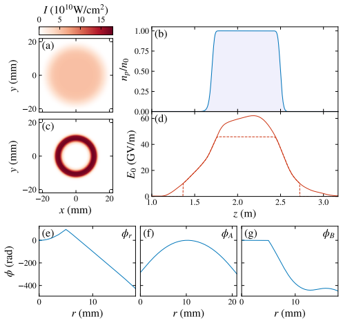
The central object is the diffractive tandem lens pair: Lens A reshapes the incoming radial intensity profile into the required intensity distribution at the z=0 plane using a geometric ray-mapping energy-conservation calculation; Lens B cancels the phase left by Lens A and adds the phase of the target Bessel field. The design algorithm extends the Bessel-superposition method of Ref. [27] to the full bandwidth of an ultrafast pulse, and couples it to the ADK ionization formula so that a target plasma density profile determines the required on-axis field. A scalar Fourier-optics propagation simulation using a discrete Hankel transform provides the predicted performance against which the exper
What would settle it
Measure the actual on-axis electron-density profile of the laser-ionized gas (e.g., with a transverse interferometer or a Stark-broadening diagnostic) at the full 192 mJ pulse energy and compare it against the density predicted from the measured on-axis fluence using Eq. (2); a systematic mismatch that grows with pulse energy would falsify the envelope-unchanged assumption.
Extended reading notes
Core claim
The central claim is that the tandem-lens design—combining a ray-optics intensity-reshaping lens with a phase-correcting second lens—can reproduce a designed on-axis electric field E0(z) over a meter-long focal region, even for broad-bandwidth ultrafast pulses. The design algorithm first converts a desired plasma density n_p(z) into a required on-axis field using the ADK tunneling ionization model, then solves for the spectrum of Bessel modes that produces that field while accounting for chromatic effects. The experiment verifies the optics: the measured on-axis fluence along the focus agrees with the simulation, and the Bessel spot width is within 3.2% of the 60-micrometer design value. The
Load-bearing premise
The design takes as given that the ionizing laser pulse keeps its temporal envelope unchanged while propagating through the gas or plasma, so the ADK tunneling-ionization model can be applied point-by-point; if the pulse self-modulates, depletes, or is otherwise reshaped at full power, the actual plasma density profile will deviate from design.
Editorial extensions
If this is right
- Laser-ionized hydrogen plasmas with tailored density ramps become practical for plasma wakefield accelerators, offering full optical access and a path to kilohertz repetition rates.
- The same phase-design algorithm can produce hollow cylindrical plasma channels by using a higher-order Bessel mode, which is of interest for positron acceleration.
- The measured agreement between simulated and actual on-axis fluence means the lens design can be trusted to produce other target profiles without re-optimizing experimentally.
- The efficiency, currently limited mostly by Fresnel reflections and phase discretization, could be improved with anti-reflective coatings and more levels, reducing the required input pulse energy.
- The source has already been used in a plasma wakefield experiment, with details reported in an upcoming publication.
Reading between the lines
- Because the validation compared laser fluence rather than ionized electron density, a direct plasma-density measurement (e.g., interferometry or Stark broadening) at the full operating power would test the ADK-based envelope-unchanged assumption.
- The chromatic phase-error analysis suggests that an iterative correction in the lens design could push the plasma-density fidelity even closer to the target, since the residual error is systematic in wavelength.
- The method should transfer to other gas species and wavelengths simply by re-running the ADK inversion, opening up alternative plasma sources for different accelerator or free-electron-laser schemes.
Editorial analysis
A structured set of objections, weighed in public.
Referee Report
Summary. The paper describes a tandem diffractive lens system designed to focus a high-power ultrafast laser into a meter-long Bessel beam with a prescribed on-axis intensity profile, intended for creating laser-ionized plasmas with tailored density ramps for plasma wakefield acceleration. Section 2 develops an algorithm that maps a target plasma density n_p(z) to a required on-axis electric field E0(z) via the ADK ionization model, then uses an extension of the Čižmár–Dholakia Bessel-mode superposition to design the lens phases. Section 3 analyzes binary-optic efficiency, Section 4 presents Fourier-optics simulations including chromatic effects, and Section 5 reports experimental characterization: a low-energy (2.7 mJ) fluence scan shows good agreement with simulation, a Bessel spot width within 3.2% of the 60 μm design value, and a high-energy (192 mJ) shot produces H-alpha emission, confirming ionization of hydrogen gas.
Significance. If the result holds, the paper demonstrates a practical, high-power-compatible alternative to SLM-based Bessel beam shaping, with quantitative agreement between measured and simulated on-axis fluence and Bessel spot size. The explicit inclusion of chromatic dispersion in the design is a useful extension beyond prior monochromatic treatments, and the experimental integration at FACET-II shows real accelerator-facility applicability. The main weakness is that the plasma-tailoring claim—the motivation for the lens system—is not directly validated: the predicted plasma density ramp is obtained from a simulation that uses the same ADK model as the design, and the only high-power measurement confirms ionization but not the longitudinal density profile.
major comments (3)
- [§5, Fig. 9] The experimental validation is carried out at 2.7 mJ, while the plasma-forming operation is at 192 mJ—a factor of 71 higher. At the high-energy level the only diagnostic is H-alpha light, which confirms ionization but not the longitudinal density ramp. The central application claim—tailored plasma ramps—therefore rests on Fig. 7(d), computed from the linear Fourier-optics simulation of App. B, Eq. (37), which omits Kerr self-focusing, ionization-induced defocusing, spectral blueshifting, and pulse depletion. A direct measurement of n_p(z), or at least an independent quantitative high-power on-axis intensity measurement, is needed to support the title claim.
- [§2, Eq. (2) and Fig. 7(d)] The predicted plasma density profile in Fig. 7(d) is obtained by inserting the simulated on-axis field into the same ADK model, Eq. (2), that was used to convert the target n_p(z) into the design E0(z). This is a consistency check of the design pipeline, not an independent validation of plasma-tailoring capability. This circularity is compounded by the caption of Fig. 9(e), which states that the simulated fluence was scaled to match the measurement; the comparison validates the shape of the on-axis fluence but not the absolute intensity that determines the ionization fraction. An independent measurement of the plasma density ramp is required.
- [§4 and App. B] The design assumes in Eq. (2) that the pulse envelope remains unchanged during propagation. The Fourier-optics simulation underlying Fig. 7 propagates each spectral component with the linear vacuum dispersion k_z = sqrt(ω^2/c^2 - k_r^2) (Eq. 37) and does not include intensity-dependent effects. Since the operating intensity is sufficient to ionize the gas, ionization-induced refraction and plasma generation can alter the focusing and the effective ramp. The paper should either include an estimate of the nonlinear propagation length and its effect on the ramp, or clearly restrict the claim to the linear, low-energy regime demonstrated.
minor comments (4)
- [§4 vs §5] The simulation in Section 4 uses a Gaussian pulse with FWHM duration of 35 fs, while Section 5 states the laser output is 45 fs FWHM. Please clarify which value corresponds to the experiment and how the difference affects the comparison.
- [Fig. 9(e)] The statement 'simulation results have been scaled to match the measurements' is important but the scaling factor is not reported. Reporting absolute fluence values and the scaling factor would strengthen the quantitative comparison.
- [§5] The low-power measurement is at 2.7 mJ, while the simulation in Section 4 is run for a 25 mJ pulse (32 mJ with losses). The relation between these energy scales and the normalization used in Fig. 9 should be stated more explicitly.
- [Eq. (20)] The floor function in the discretization formula is not clearly typeset; use an explicit floor notation such as \lfloor \cdot \rfloor to avoid ambiguity.
Circularity Check
Optical focusing claim is independently measured, but the simulated plasma-density ramp is a round-trip of the ADK design input rather than an independent prediction.
-
self definitional
[Section 4, Fig. 7(d); design inputs in Section 2 Eq. (2) and Fig. 6(d)]
"The expected on-axis plasma density, calculated using the ADK expression, is only slightly distorted despite the significant chromatic aberrations in the tandem lenses."
The design pipeline begins with a target plasma density n_p(z), numerically inverts Eq. (2) (ADK) to obtain E0(z), smooths that field, and computes the lens phases from it. The simulation then propagates the field using the same scalar Bessel-mode/k_z relation used in the design (Eqs. 3-8 and Eq. 37) and converts the propagated E0 back to n_p with the same ADK expression. Thus the predicted density profile is essentially ADK(ADK^{-1}(n_target)) plus small chromatic residuals: agreement with the target is baked in by construction. This is a numerical round-trip, not an independent test of plasma shaping. The only independent experimental check in the paper is the low-power fluence measurement of Fig. 9; the plasma density ramp itself is never measured.
full rationale
The central optical demonstration is externally grounded: a rail camera measured the on-axis fluence at 2.7 mJ, and the shape agrees with the Fourier-optics simulation; the measured Bessel-spot width is within 3.2% of the 60 micron design value. That comparison is not a fit to the data and provides genuine independent support for the lens-design algorithm. The circular element is confined to the simulated plasma-density profile of Fig. 7(d): because the lens phases are derived by inverting the ADK model for a chosen density profile, and the simulation uses the same propagation model and the same ADK model to compute the resulting density, the predicted ramp is a consistency loop rather than a falsifiable prediction. The paper does label this as simulation, not measurement, which softens the issue, but the conclusion leans on this simulation to claim that control of the plasma profile for PWFA is achievable. The high-power plasma is only confirmed via H-alpha emission, not by a density-profile measurement, so nonlinear-propagation effects (Kerr self-focusing, ionization defocusing, pulse depletion, spectral shifting) are an unvalidated risk; that is a correctness concern rather than circularity. Self-citations in the paper are background and are not load-bearing. Taking all this into account, the paper is partially circular only in its simulated plasma-density prediction, while the main optical claim remains independently measured.
Assumptions & free parameters
free parameters (3)
- Smoothed target on-axis field E0(z) =
Smoothed version of ADK-derived E0 with taper below 0.5% ionization (Fig. 1c, Fig. 6d)
- Bessel spot radius R_b =
60 micrometers (design), 120 micrometers in example
- Lens separation L =
1 m
assumptions (7)
- domain assumption ADK tunneling ionization model
- ad hoc to paper Pulse envelope unchanged during propagation
- standard math Scalar wave equation and scalar diffraction theory
- domain assumption Ray optics energy conservation for Lens A amplitude mapping
- ad hoc to paper Monochromatic approximation at the z=0 plane
- domain assumption Single-electron ionization of H2 with 15.4 eV is the dominant pathway
- domain assumption Linear propagation of the focused laser through the plasma
Cite this review
Pith. "Pith review of Demonstration of a tandem lens for producing shaped laser-ionized plasmas for plasma wakefield acceleration." pith.science (2026). https://pith.science/paper/MDXGQNA5
@misc{pith2026250901747,
  author       = {Pith},
  title        = {Pith review of: Demonstration of a tandem lens for producing shaped laser-ionized plasmas for plasma wakefield acceleration},
  year         = {2026},
  howpublished = {\url{https://pith.science/paper/MDXGQNA5}},
  note         = {Machine review of arXiv:2509.01747}
}
read the original abstract
We demonstrate a tandem lens optical setup, comprising two diffractive optics, that focuses a high-power ultrafast laser with a shaped on-axis intensity profile, producing a meter-long Bessel focus. The intended use of the optical setup is to produce a laser-ionized plasma source for plasma wakefield acceleration. By controlling the on-axis intensity, the density profile of the plasma ramps at the entrance and exit of the plasma can be tailored to optimize matching of the electron beam into the plasma. In addition to demonstrating the optical system, we describe the algorithm used to calculate the lens phases and present detailed calculations of the lenses' expected performance.
Figures


Figures from the paper (6 more)




Reference graph
Works this paper leans on
-
[1]
Multi-gev energy gain in a plasma-wakefield accelerator,
M. J. Hogan, C. D. Barnes, C. E. Clayton,et al., “Multi-gev energy gain in a plasma-wakefield accelerator,” Phys. Rev. Lett.95, 054802 (2005)
work page 2005
-
[2]
Energy doubling of 42 gev electrons in a metre-scale plasma wakefield accelerator,
I. Blumenfeld, C. E. Clayton, F.-J. Decker,et al., “Energy doubling of 42 gev electrons in a metre-scale plasma wakefield accelerator,” Nature445, 741–744 (2007)
work page 2007
-
[3]
A beam driven plasma-wakefield linear collider: from higgs factory to multi-tev,
E. Adli, J.-P. Delahaye, S. J. Gessner,et al., “A beam driven plasma-wakefield linear collider: from higgs factory to multi-tev,” arXiv preprint arXiv:1308.1145 (2013)
arXiv 2013
-
[4]
B. Foster, R. D’Arcy, and C. A. Lindstrøm, “A hybrid, asymmetric, linear higgs factory based on plasma-wakefield and radio-frequency acceleration,” New J. Phys.25, 093037 (2023)
work page 2023
-
[5]
Exploring the quantum universe: Pathways to innovation and discovery in particle physics,
S. Asai, A. Ballarino, T. Bose,et al., “Exploring the quantum universe: Pathways to innovation and discovery in particle physics,” arXiv preprint arXiv:2407.19176 (2024)
arXiv 2024
-
[6]
Towards a table-top free-electron laser,
K. Nakajima, “Towards a table-top free-electron laser,” Nat. Phys.4, 92–93 (2008)
work page 2008
-
[7]
Free-electron lasing at 27 nanometres based on a laser wakefield accelerator,
W. Wang, K. Feng, L. Ke,et al., “Free-electron lasing at 27 nanometres based on a laser wakefield accelerator,” Nature 595, 516–520 (2021)
work page 2021
-
[8]
Free-electron lasing with compact beam-driven plasma wakefield accelerator,
R. Pompili, D. Alesini, M. Anania,et al., “Free-electron lasing with compact beam-driven plasma wakefield accelerator,” Nature605, 659–662 (2022)
work page 2022
Show all 48 references
-
[9]
Seeded free-electron laser driven by a compact laser plasma accelerator,
M. Labat, J. C. Cabadağ, A. Ghaith,et al., “Seeded free-electron laser driven by a compact laser plasma accelerator,” Nat. Photonics17, 150–156 (2023)
2023
-
[10]
Photo-ionized lithium source for plasma accelerator applications,
P. Muggli, K. Marsh, S. Wang,et al., “Photo-ionized lithium source for plasma accelerator applications,” IEEE Trans. on Plasma Sci.27, 791–799 (1999)
1999
-
[11]
High-efficiency acceleration of an electron beam in a plasma wakefield accelerator,
M. Litos, E. Adli, W. An,et al., “High-efficiency acceleration of an electron beam in a plasma wakefield accelerator,” Nature 515, 92–95 (2014)
2014
-
[12]
9 gev energy gain in a beam-driven plasma wakefield accelerator,
M. Litos, E. Adli, J. Allen,et al., “9 gev energy gain in a beam-driven plasma wakefield accelerator,” Plasma Phys. Control. Fusion58, 034017 (2016)
2016
-
[13]
Ionization-induced electron trapping in ultrarelativistic plasma wakes,
E. Oz, S. Deng, T. Katsouleas,et al., “Ionization-induced electron trapping in ultrarelativistic plasma wakes,” Phys. Rev. Lett.98, 084801 (2007)
2007
-
[14]
Evidence for high-energy and low-emittance electron beams using ionization injection of charge in a plasma wakefield accelerator,
N. Vafaei-Najafabadi, W. An, C. Clayton,et al., “Evidence for high-energy and low-emittance electron beams using ionization injection of charge in a plasma wakefield accelerator,” Plasma Phys. Control. Fusion58, 034009 (2016)
2016
-
[15]
Energy-spread preservation and high efficiency in a plasma-wakefield accelerator,
J. Garland, G. Boyle, P. Gonzalezet al., “Energy-spread preservation and high efficiency in a plasma-wakefield accelerator,” Phys. Rev. Lett.126, 014801 (2021)
2021
-
[16]
Emittancepreservationinaplasma-wakefieldaccelerator,
C.Lindstrøm,J.Beinortait ˙e,J.BjörklundSvensson, etal.,“Emittancepreservationinaplasma-wakefieldaccelerator,” Nat. Commun.15, 6097 (2024)
2024
-
[17]
Energy depletion and re-acceleration of driver electrons in a plasma-wakefield accelerator,
F. Peña, C. A. Lindstrøm, J. Beinortait˙e, et al., “Energy depletion and re-acceleration of driver electrons in a plasma-wakefield accelerator,” Phys. Rev. Res.6, 043090 (2024)
2024
-
[18]
Generation and acceleration of electron bunches from a plasma photocathode,
A. Deng, O. Karger, T. Heinemann,et al., “Generation and acceleration of electron bunches from a plasma photocathode,” Nat. Phys.15, 1156–1160 (2019)
2019
-
[19]
Physics of phase space matching for staging plasma and traditional accelerator components using longitudinally tailored plasma profiles,
X. Xu, J. Hua, Y. Wu,et al., “Physics of phase space matching for staging plasma and traditional accelerator components using longitudinally tailored plasma profiles,” Phys. Rev. Lett.116, 124801 (2016)
2016
-
[20]
Beam emittance preservation using gaussian density ramps in a beam-driven plasma wakefield accelerator,
M. Litos, R. Ariniello, C. Doss,et al., “Beam emittance preservation using gaussian density ramps in a beam-driven plasma wakefield accelerator,” Philos. Trans. Royal Soc. A377, 20180181 (2019)
2019
-
[21]
Transverse beam dynamics in a plasma density ramp,
R. Ariniello, C. Doss, K. Hunt-Stone,et al., “Transverse beam dynamics in a plasma density ramp,” Phys. Rev. Accel. Beams 22, 041304 (2019)
2019
-
[22]
Emittance preservation through density ramp matching sections in a plasma wakefield accelerator,
Y. Zhao, W. An, X. Xu,et al., “Emittance preservation through density ramp matching sections in a plasma wakefield accelerator,” Phys. Rev. Accel. Beams23, 011302 (2020)
2020
-
[23]
Chromatic transverse dynamics in a nonlinear plasma accelerator,
R. Ariniello, C. Doss, V. Lee,et al., “Chromatic transverse dynamics in a nonlinear plasma accelerator,” Phys. Rev. Res. 4, 043120 (2022)
2022
-
[24]
Dissipation of electron-beam-driven plasma wakes,
R. Zgadzaj, T. Silva, V. Khudyakov,et al., “Dissipation of electron-beam-driven plasma wakes,” Nat. Commun.11, 4753 (2020)
2020
-
[25]
Direct observation of plasma waves and dynamics induced by laser-accelerated electron beams,
M. Gilljohann, A. Döpp, J. Götzfried,et al., “Direct observation of plasma waves and dynamics induced by laser-accelerated electron beams,” Phys. Rev. X9, 011046 (2019)
2019
-
[26]
Temporal evolution of the light emitted by a thin, laser-ionized plasma source,
V. Lee, R. Ariniello, C. Doss,et al., “Temporal evolution of the light emitted by a thin, laser-ionized plasma source,” Phys. Plasmas31 (2024)
2024
-
[27]
Tunable bessel light modes: engineering the axial propagation,
T. Čižmár and K. Dholakia, “Tunable bessel light modes: engineering the axial propagation,” Opt. Express17, 15558 (2009)
2009
-
[28]
Tunable bessel beam shaping for robust atmospheric optical communication,
Z. Lu, Z. Guo, M. Fan,et al., “Tunable bessel beam shaping for robust atmospheric optical communication,” J. Light. Technol. 40, 5097–5106 (2022)
2022
-
[29]
Attenuation-free non-diffracting bessel beams,
Q. Fontaine, H. Hu, S. Pigeon,et al., “Attenuation-free non-diffracting bessel beams,” Opt. Express27, 30067–30080 (2019)
2019
-
[30]
Non-diffractingandself-acceleratingbesselbeamswithon-demandtailoredintensity profiles along arbitrary trajectories,
W.Yan,Y.Gao,Z.Yuan, etal.,“Non-diffractingandself-acceleratingbesselbeamswithon-demandtailoredintensity profiles along arbitrary trajectories,” Opt. Lett.46, 1494–1497 (2021)
2021
-
[31]
Arbitraryshapingofon-axisamplitudeoffemtosecondbesselbeams with a single phase-only spatial light modulator,
I.Ouadghiri-Idrissi,R.Giust,L.Froehly, etal.,“Arbitraryshapingofon-axisamplitudeoffemtosecondbesselbeams with a single phase-only spatial light modulator,” Opt. Express24, 11495 (2016)
2016
-
[32]
Tandem systems for efficient generation of uniform-axial-intensity bessel fields,
M. Honkanen and J. Turunen, “Tandem systems for efficient generation of uniform-axial-intensity bessel fields,” Opt. Commun. 154, 368 (1998)
1998
-
[33]
Diffractive optics for axial intensity shaping of bessel beams,
R. Dharmavarapu, S. Bhattacharya, and S. Juodkazis, “Diffractive optics for axial intensity shaping of bessel beams,” J. Opt.20, 085606 (2018)
2018
-
[34]
Experimental investigation of strong-field-ionization theories for laser fields from visible to midinfrared frequencies,
Y. H. Lai, J. Xu, U. B. Szafruga,et al., “Experimental investigation of strong-field-ionization theories for laser fields from visible to midinfrared frequencies,” Phys. Rev. A96, 063417 (2017)
2017
-
[35]
Tunnel ionization of complex atoms and of atomic ions in an alternating electromagnetic field,
M. Ammosov, N. Delone, and V. Krainov, “Tunnel ionization of complex atoms and of atomic ions in an alternating electromagnetic field,” Sov. Phys. JETP64, 1191 (1986)
1986
-
[36]
Ionization of atoms in an alternating electric field,
A. Perelomov, V. Popov, and M. Terent’Ev, “Ionization of atoms in an alternating electric field,” Sov. Phys. JETP23, 924 (1966)
1966
-
[37]
Nonparaxial design of generalized axicons,
J. Sochacki, A. Kołodziejczyk, Z. Jaroszewicz, and S. Bara, “Nonparaxial design of generalized axicons,” Appl. Opt. 31, 5326 (1992)
1992
-
[38]
Demonstration of a positron beam-driven hollow channel plasma wakefield accelerator,
S. Gessner, E. Adli, J. M. Allen,et al., “Demonstration of a positron beam-driven hollow channel plasma wakefield accelerator,” Nat. Commun.7, 11785 (2016)
2016
-
[39]
G. J. Swansonet al., Binary optics technology: the theory and design of multi-level diffractive optical elements, vol. 854 (Massachusetts Institute of Technology, Lincoln Laboratory Cambridge, MA, USA, 1989)
1989
-
[40]
Born and E
M. Born and E. Wolf,Principles of optics: electromagnetic theory of propagation, interference and diffraction of light (Elsevier, 2013)
2013
-
[41]
Binary optics technology: theoretical limits on the diffraction efficiency of multilevel diffractive optical elements,
G. J. Swanson, “Binary optics technology: theoretical limits on the diffraction efficiency of multilevel diffractive optical elements,” (1991)
1991
-
[42]
Optical performance of holographic kinoforms,
D. A. Buralli, G. M. Morris, and J. R. Rogers, “Optical performance of holographic kinoforms,” Appl. Opt.28, 976–983 (1989)
1989
-
[43]
Computation of quasi-discrete hankel transforms of integer order for propagating optical wave fields,
M. Guizar-Sicairos and J. C. Gutiérrez-Vega, “Computation of quasi-discrete hankel transforms of integer order for propagating optical wave fields,” JOSA A21, 53–58 (2004)
2004
-
[44]
Axiparabola: anewtoolforhigh-intensityoptics,
K.Oubrerie,I.A.Andriyash,R.Lahaye, etal.,“Axiparabola: anewtoolforhigh-intensityoptics,”J.Opt. 24,045503 (2022)
2022
-
[45]
Cross-polarized common-path temporal interferometry for high-sensitivity strong-field ionization measurements,
Z. Nie, N. Nambu, K. A. Marsh,et al., “Cross-polarized common-path temporal interferometry for high-sensitivity strong-field ionization measurements,” Opt. Express30, 25696–25706 (2022)
2022
-
[46]
Facet-ii facility for advanced accelerator experimental tests,
V. Yakimenko, L. Alsberg, E. Bong,et al., “Facet-ii facility for advanced accelerator experimental tests,” Phys. Rev. Accel. Beams22, 101301 (2019)
2019
-
[47]
Laser ionized preformed plasma at facet,
S. Green, E. Adli, C. Clarke,et al., “Laser ionized preformed plasma at facet,” Plasma Phys. Control. Fusion56, 084011 (2014)
2014
-
[48]
Wakefield generation in hydrogen and lithium plasmas at facet-ii: Diagnostics and first beam-plasma interaction results,
D. Storey, C. Zhang, P. San Miguel Claveria,et al., “Wakefield generation in hydrogen and lithium plasmas at facet-ii: Diagnostics and first beam-plasma interaction results,” Phys. Rev. Accel. Beams27, 051302 (2024)
2024
Reviewed August 5, 2026 · model on record in the stance chip above.
Discussion (0). Sign in to comment.