Equivalent Circuit Modeling of Grid-Forming Inverters in (Sub)-Transient Time-Frame
Pith reviewed 2026-05-16 02:28 UTC · model grok-4.3
The pith
Grid-forming inverters maintain constant voltage at the filter capacitor, enabling an equivalent impedance model from admittance plots.
A machine-rendered reading of the paper's core claim, the machinery that carries it, and where it could break.
Core claim
The paper claims that the widely accepted definition of a grid-forming inverter as a constant voltage source behind an impedance is realized by maintaining constant voltage at the filter capacitor, and that frequency-domain admittance plots provide a systematic way to quantify this effective impedance for black-box models, allowing accurate representation of sub-transient dynamics and stability limits.
What carries the argument
The equivalent circuit model derived from frequency-domain admittance plots of the black-box GFM, positioning the constant voltage source behind the impedance at the filter capacitor.
Load-bearing premise
That an idealistic GFM maintains a nearly constant voltage across the filter capacitor and that admittance plots fully quantify the impedance for sub-transient behavior.
What would settle it
A simulation where the equivalent circuit model fails to match the detailed GFM response in sub-transient dynamics or stability metrics in a test system beyond the IEEE-39 bus.
Figures
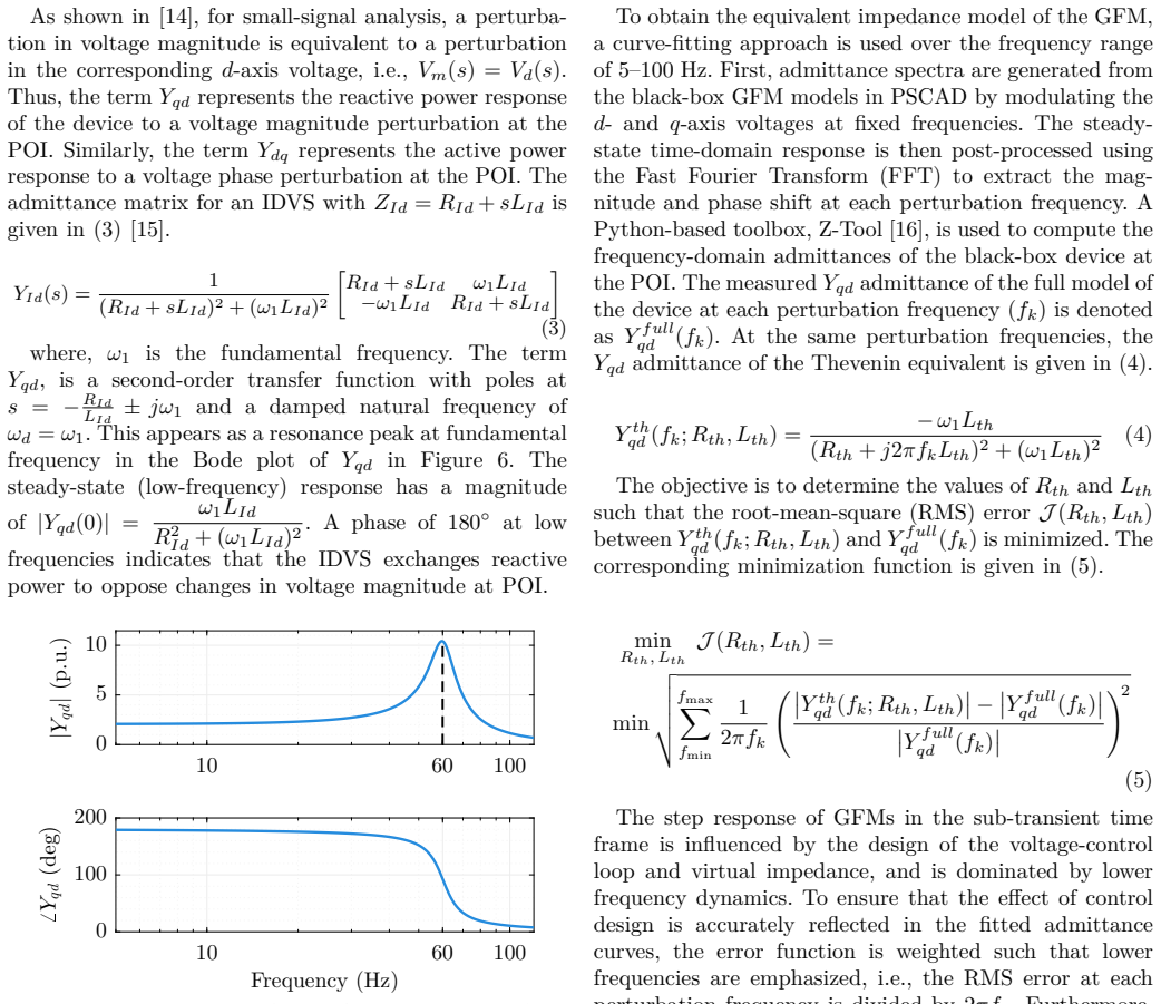
read the original abstract
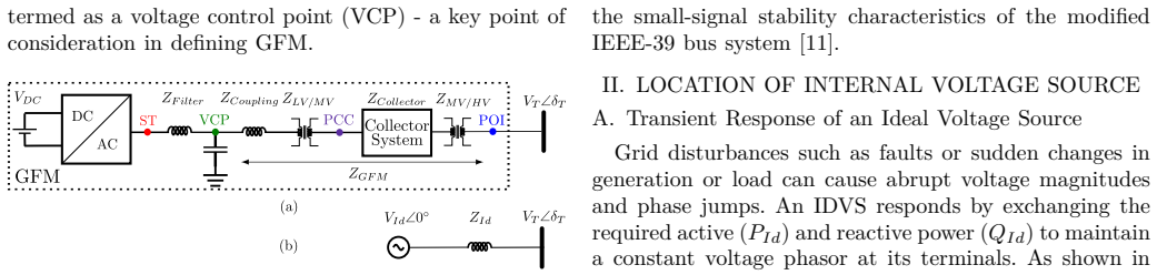
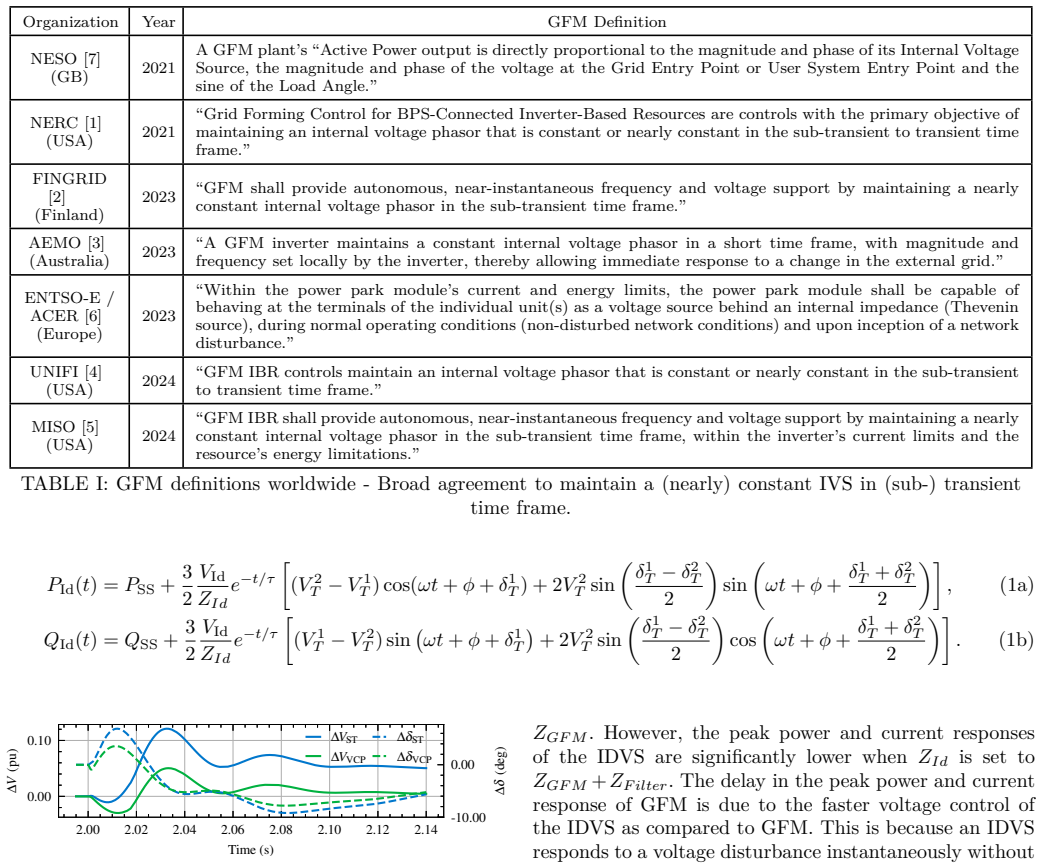
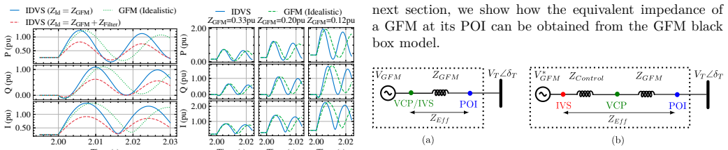
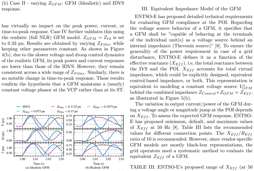
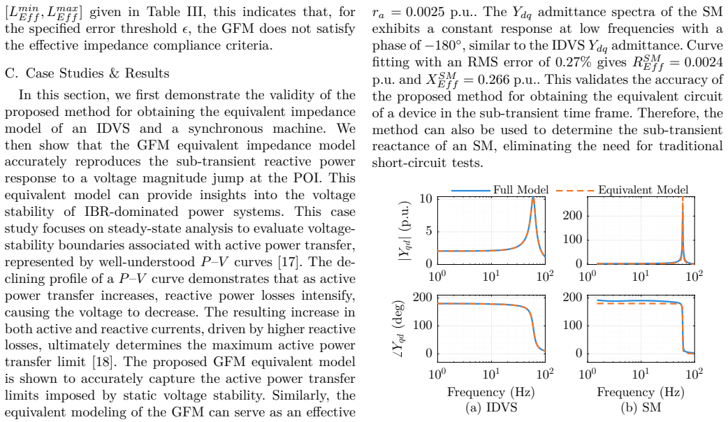
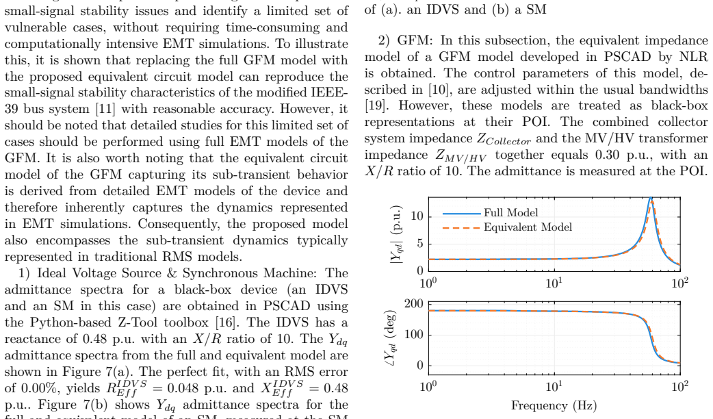
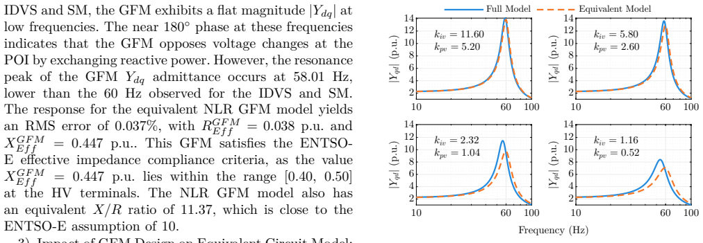
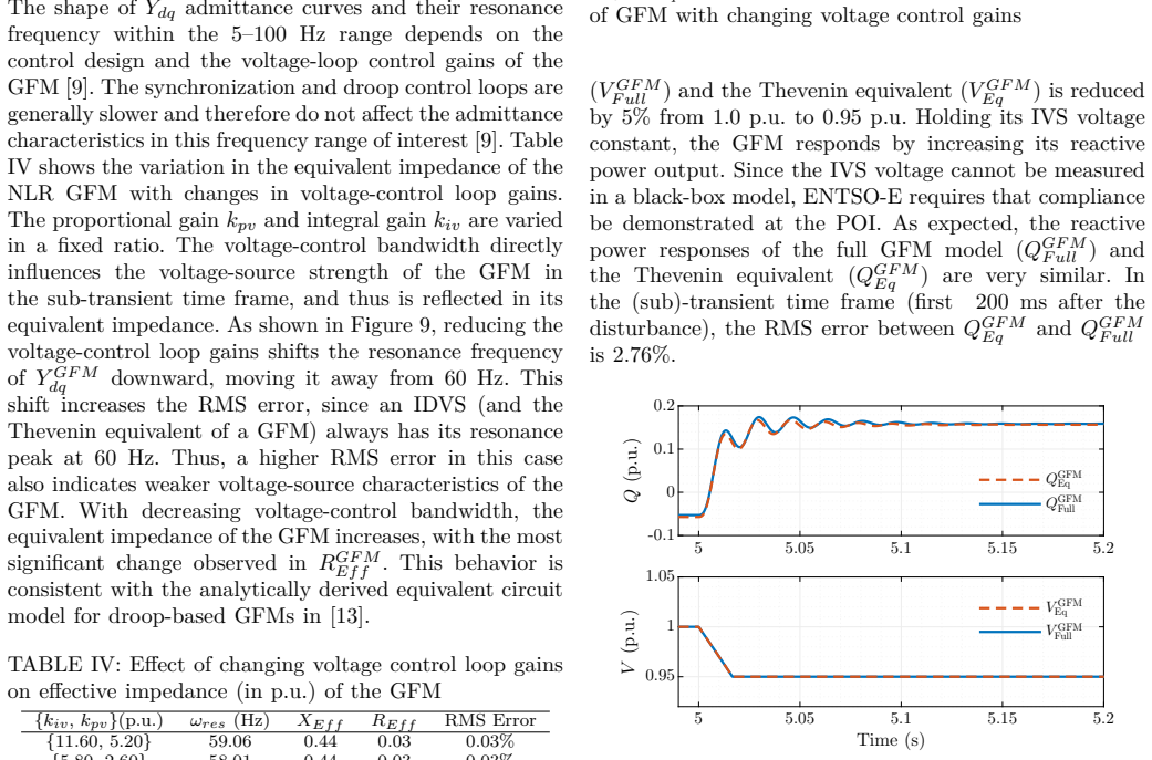
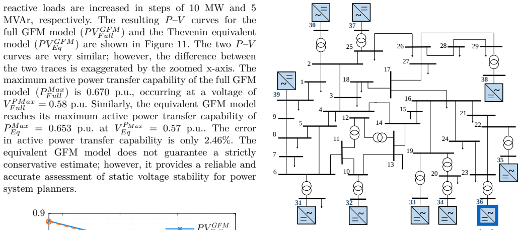
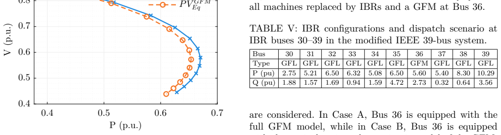
The widely accepted definition of grid-forming (GFM) inverter states that it should behave as a (nearly) constant voltage source behind an impedance by maintaining a (nearly) constant internal voltage phasor in the sub-transient to transient time frame. Some system operators further mandate permissible ranges for this effective impedance. However, these specifications do not clearly define the location of the internal voltage source, and no systematic method exists to quantify its effective impedance for a black-box GFM model. To address this, we first compare the transient responses of an ideal voltage source and a GFM to show that an idealistic GFM maintains a (nearly) constant voltage across the filter capacitor, rather than at the inverter switches. Then we propose a systematic method to quantify the effective impedance of a GFM from its black-box model using frequency-domain admittance plots. Using standard PSCAD GFM models developed by NLR (formerly NREL), we demonstrate that the GFM's equivalent impedance model captures the sub-transient response and static voltage stability limit accurately. Further, replacing the GFM with the proposed equivalent circuit model in the modified IEEE-39 bus system is shown to reproduce the small-signal stability characteristics with reasonable accuracy.
Editorial analysis
A structured set of objections, weighed in public.
Referee Report
Summary. The paper claims that grid-forming (GFM) inverters behave as a nearly constant voltage source behind an impedance in the sub-transient to transient timeframe, with the internal voltage located across the filter capacitor rather than the switches. It proposes extracting the effective impedance systematically from black-box frequency-domain admittance plots, validates the resulting equivalent circuit against PSCAD GFM models for sub-transient response and static voltage stability, and shows that substituting the equivalent circuit into a modified IEEE-39 bus system reproduces small-signal stability characteristics with reasonable accuracy.
Significance. If the validation holds, the work supplies a practical, black-box-compatible method to meet system-operator impedance specifications for GFM units and enables reduced-order modeling for stability studies without requiring full control details. The use of standard NLR PSCAD models and the IEEE-39 demonstration are concrete strengths that could improve reproducibility in the field.
major comments (3)
- [Abstract] The central validation for sub-transient response (Abstract) is performed only on the isolated NLR PSCAD GFM unit; no large-signal fault or disturbance waveforms are shown when the equivalent circuit replaces the GFM inside the IEEE-39 system. Because frequency-domain admittance extraction is inherently small-signal and linear, the claim that the same circuit “captures the sub-transient response accurately” under control saturation or current limiting remains unsupported.
- [Abstract] No quantitative error metrics (e.g., RMS voltage or current deviation, phase-error bounds) are reported for either the isolated-unit sub-transient comparisons or the IEEE-39 small-signal eigenvalue matches. The phrase “reasonable accuracy” is therefore impossible to assess against typical engineering tolerances.
- [Abstract] The assumption that an idealistic GFM maintains a nearly constant voltage across the filter capacitor (Abstract) is stated without a supporting derivation or sensitivity study showing how this location is identified from the admittance data versus alternative reference points (e.g., switch terminals).
minor comments (2)
- The manuscript should include a brief limitations paragraph discussing the small-signal nature of the admittance extraction and the operating-point range over which the equivalent circuit remains valid.
- Figure captions and axis labels for the frequency-domain admittance plots and time-domain waveforms should explicitly state the perturbation amplitude used for admittance extraction and the fault severity used for time-domain checks.
Simulated Author's Rebuttal
We thank the referee for the constructive comments, which help clarify the scope and strengthen the presentation of our work. We address each major comment point by point below and have revised the manuscript to incorporate clarifications and additional quantitative details where feasible.
read point-by-point responses
-
Referee: [Abstract] The central validation for sub-transient response (Abstract) is performed only on the isolated NLR PSCAD GFM unit; no large-signal fault or disturbance waveforms are shown when the equivalent circuit replaces the GFM inside the IEEE-39 system. Because frequency-domain admittance extraction is inherently small-signal and linear, the claim that the same circuit “captures the sub-transient response accurately” under control saturation or current limiting remains unsupported.
Authors: We agree that the sub-transient validation is performed exclusively on the isolated GFM unit, as stated in the manuscript. The IEEE-39 study is limited to small-signal stability to demonstrate the utility of the reduced-order model in a multi-machine setting. The equivalent circuit is derived from small-signal admittance data and is not intended to represent behavior under control saturation or current limiting; the abstract does not claim such coverage. We will revise the abstract to explicitly note that sub-transient validation applies to the isolated unit under linear operating conditions and that the IEEE-39 results pertain to small-signal analysis. revision: yes
-
Referee: [Abstract] No quantitative error metrics (e.g., RMS voltage or current deviation, phase-error bounds) are reported for either the isolated-unit sub-transient comparisons or the IEEE-39 small-signal eigenvalue matches. The phrase “reasonable accuracy” is therefore impossible to assess against typical engineering tolerances.
Authors: We acknowledge that the absence of quantitative metrics makes the term “reasonable accuracy” difficult to evaluate. In the revised manuscript we will add RMS voltage and current deviation values for the isolated-unit waveform comparisons and report maximum eigenvalue deviation or damping ratio differences for the IEEE-39 small-signal results, allowing direct comparison with typical engineering tolerances. revision: yes
-
Referee: [Abstract] The assumption that an idealistic GFM maintains a nearly constant voltage across the filter capacitor (Abstract) is stated without a supporting derivation or sensitivity study showing how this location is identified from the admittance data versus alternative reference points (e.g., switch terminals).
Authors: The manuscript already contains a direct comparison of transient responses between an ideal voltage source and the GFM model that identifies the filter capacitor voltage as the appropriate internal reference. This is corroborated by the admittance plots, which align with a voltage-behind-impedance representation at that location. To address the request for a more explicit derivation and sensitivity analysis, we will add a brief subsection (or appendix) that formalizes the identification procedure and includes a sensitivity comparison of capacitor versus switch-terminal voltage under varying operating points. revision: yes
Circularity Check
No significant circularity in derivation chain
full rationale
The paper extracts effective impedance directly from frequency-domain admittance plots of the black-box GFM model and then validates the resulting equivalent circuit against time-domain sub-transient responses and small-signal stability metrics in the IEEE-39 system. This extraction is a direct computation from the model's own data rather than a self-definitional loop, a fitted parameter renamed as prediction, or a load-bearing self-citation. The central claim is an approximation whose accuracy is checked against independent simulation benchmarks, keeping the derivation self-contained without reduction to its inputs by construction.
Axiom & Free-Parameter Ledger
axioms (1)
- domain assumption An idealistic GFM maintains a nearly constant voltage across the filter capacitor in the sub-transient to transient time frame
Lean theorems connected to this paper
-
IndisputableMonolith/Cost/FunctionalEquationwashburn_uniqueness_aczel unclear?
unclearRelation between the paper passage and the cited Recognition theorem.
propose a systematic method to quantify the effective impedance of a GFM from its black-box model using frequency-domain admittance plots
What do these tags mean?
- matches
- The paper's claim is directly supported by a theorem in the formal canon.
- supports
- The theorem supports part of the paper's argument, but the paper may add assumptions or extra steps.
- extends
- The paper goes beyond the formal theorem; the theorem is a base layer rather than the whole result.
- uses
- The paper appears to rely on the theorem as machinery.
- contradicts
- The paper's claim conflicts with a theorem or certificate in the canon.
- unclear
- Pith found a possible connection, but the passage is too broad, indirect, or ambiguous to say the theorem truly supports the claim.
Forward citations
Cited by 1 Pith paper
-
Frequency-Domain Compliance Assessment of Grid-Forming Devices
A frequency-domain compliance criterion based on minimum expected P(s)/theta(s) and Q(s)/V(s) Bode plots is proposed for grid-forming inverters, shown equivalent to time-domain tests and demonstrated on models with st...
Reference graph
Works this paper leans on
-
[1]
Grid-forming technology: White paper ,
North American Electric Reliability Corporation (NERC), “Grid-forming technology: White paper ,” NERC, Tech. Rep., Dec. 2021
work page 2021
-
[2]
Specific study requirements for grid energy stor- age systems, version 1.0 ,
Fingrid Oyj, “ Specific study requirements for grid energy stor- age systems, version 1.0 ,” Fingrid Oyj, Tech. Rep., Jun. 2023
work page 2023
-
[3]
Voluntary spec- ification for grid-forming inverters ,
Australian Energy Market Operator (AEMO), “ Voluntary spec- ification for grid-forming inverters ,” AEMO, Tech. Rep., May 2023
work page 2023
-
[4]
UNIFI specifications for grid-forming inverter-based resources: Version 2 ,
UNIFI Consortium, “ UNIFI specifications for grid-forming inverter-based resources: Version 2 ,” UNIFI Consortium, Tech. Rep., Mar. 2024
work page 2024
-
[5]
Midcontinent Independent System Operator (MISO), “ Grid- forming battery energy storage capabilities, performance, and simulation test requirements proposal ,” MISO, Tech. Rep., Jul. 2024
work page 2024
-
[6]
Recommendation No 03/2023 of the European Union Agency for the Cooperation of Energy Regulators ,
Agency for the Cooperation of Energy Regulators (ACER), “Recommendation No 03/2023 of the European Union Agency for the Cooperation of Energy Regulators ,” ACER, Tech. Rep., Dec. 2023
work page 2023
-
[7]
National Grid Electricity System Operator (ESO), “ Workgroup consultation GC0137: Minimum specification required for provi- sion of GB grid forming (GBGF) capability ,” ESO, Tech. Rep., Mar. 2021
work page 2021
-
[8]
Grid forming capability of power park modules: First interim report on technical requirements ,
European Network of Transmission System Operators for Elec- tricity, “ Grid forming capability of power park modules: First interim report on technical requirements ,” ENTSO-E, Tech. Rep., May 2024
work page 2024
-
[9]
Electric Power Research Institute (EPRI), “ An overview of grid- forming inverter technologies and the readiness of power systems worldwide to deploy the technology ,” EPRI, Tech. Rep., Dec. 2024
work page 2024
-
[10]
R. W. Kenyon, A. Sajadi, A. Hoke, and B.-M. Hodge, “Open- source PSCAD grid-following and grid-forming inverters and a benchmark for zero-inertia power system simulations,” in Proc. IEEE Kansas Power and Energy Conf. (KPEC), Apr. 2021, pp. 1–6
work page 2021
-
[11]
Benchmark Systems for Small-Signal Stability Analysis and Control ,
IEEE PES Task Force on Benchmark Systems for Stability Con- trols, “ Benchmark Systems for Small-Signal Stability Analysis and Control ,” IEEE Power & Energy Society, Tech. Rep. PES- TR18, Aug. 2015
work page 2015
-
[12]
N. R. Klaes and J. Fortmann, “Immunity of grid-forming control without energy storage to transient changes of grid frequency and phase,” IEEE Open J. Ind. Electron. Soc., vol. 6, pp. 265– 276, 2025
work page 2025
-
[13]
Y. Li, Y. Gu, Y. Zhu, A. Junyent-Ferré, X. Xiang, and T. C. Green, “Impedance circuit model of grid-forming inverter: Vi- sualizing control algorithms as circuit elements,” IEEE Trans. Power Electron., vol. 36, no. 3, pp. 3377–3395, 2021
work page 2021
-
[14]
Impedance modeling of three-phase voltage source converters in dq, sequence, and phasor domains,
S. Shah and L. Parsa, “Impedance modeling of three-phase voltage source converters in dq, sequence, and phasor domains,” IEEE Transactions on Energy Conversion, vol. 32, no. 3, pp. 1139–1150, 2017
work page 2017
-
[15]
A testing framework for grid-forming resources,
S. Shah, W. Yan, P. Koralewicz, V. Gevorgian, D. Ramasubra- manian, R. Wallen, A. Hoke, B. Kroposki, and B. Mather, “A testing framework for grid-forming resources,” in 2023 IEEE Power & Energy Society General Meeting (PESGM), 2023, pp. 1–5
work page 2023
-
[16]
Automated frequency- domain small-signal stability analysis of electrical energy hubs,
F. J. Cifuentes Garcia, T. Roose, Ö. C. Sakinci, D. Lee, L. Dewangan, E. A vdiaj, and J. Beerten, “Automated frequency- domain small-signal stability analysis of electrical energy hubs,” in 2024 IEEE PES Innovative Smart Grid Technologies Europe (ISGT EUROPE), 2024, pp. 1–6. 24th Power Systems Computation Conference PSCC 2026 Limassol, Cyprus — June 8-12, 2026
work page 2024
-
[17]
Evaluation of pv and qv based voltage stability analyses in converter dominated power systems,
V. Sewdien, R. Preece, J. R. Torres, and M. van der Meijden, “Evaluation of pv and qv based voltage stability analyses in converter dominated power systems,” in 2018 IEEE PES Asia- Pacific Power and Energy Engineering Conference (APPEEC), 2018, pp. 161–165
work page 2018
-
[18]
J. D. Glover, M. S. Sarma, and T. J. Overbye, Power System Analysis and Design, 4th ed. Stamford, CT: Thomson, 2008
work page 2008
-
[19]
UNIFI’s Grid-Forming (GFM) Inverter Reference Design ,
D. Chatterjee, J. Triemstra, C. Macías, W. Cai, K. Tatkare, R. Mallik, and B. Johnson, “ UNIFI’s Grid-Forming (GFM) Inverter Reference Design ,” The University of Texas at Austin, Technical Report NREL/TP-5D00-92994, July 2025
work page 2025
-
[20]
EMT— RMS modeling trade-off for IBR-driven sub-synchronous oscil- lations,
M. S. Javaid, B. Chaudhuri, F. Teng, and Z. Akhtar, “EMT— RMS modeling trade-off for IBR-driven sub-synchronous oscil- lations,” IEEE Transactions on Power Systems, 2025. 24th Power Systems Computation Conference PSCC 2026 Limassol, Cyprus — June 8-12, 2026
work page 2025
discussion (0)
Sign in with ORCID, Apple, or X to comment. Anyone can read and Pith papers without signing in.