A thermoelastic limit on the focal intensity in Fabry-P\'erot cavities
Pith reviewed 2026-05-10 17:28 UTC · model grok-4.3
The pith
Thermoelastic deformation from mirror absorption limits focal intensity in Fabry-Pérot cavities.
A machine-rendered reading of the paper's core claim, the machinery that carries it, and where it could break.
Core claim
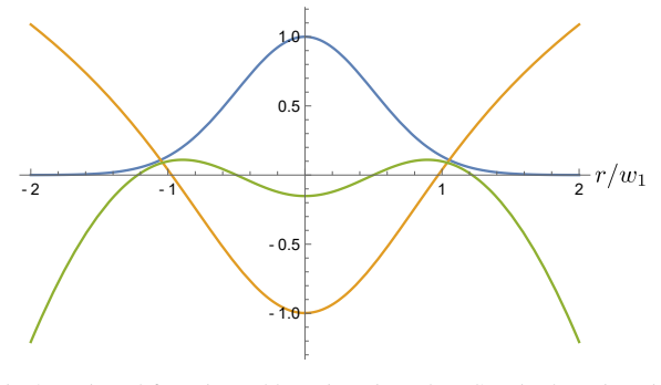
Light in the mode of a Fabry-Pérot cavity heats the mirror surfaces via optical absorption, causing thermoelastic deformation of the mirror substrates, which in turn dictates the shape of the mode. We develop an analytical model which predicts that this effect limits the maximum focal intensity of the mode. Using two near-concentric Fabry-Pérot cavities—one with 4.5-fold higher mirror absorption than the other—we measure the thermoelastic properties of the cavity mirrors and demonstrate that it is possible to achieve at least 70% of this predicted limit (in the high-absorption cavity), and that the predicted limit is 2.9 TW/cm² (in the low-absorption cavity).
What carries the argument
Analytical model coupling absorbed optical power to thermoelastic mirror deformation and the resulting change in cavity mode shape.
If this is right
- The maximum focal intensity is bounded by the balance between absorbed heat and the resulting surface deformation.
- In high-absorption cavities, intensities can still reach at least 70% of the model limit before deformation prevents further increase.
- Lower-absorption mirrors raise the intensity ceiling to 2.9 TW/cm².
- Cavity designs for high-power operation must incorporate this thermoelastic feedback to maintain desired mode shapes.
Where Pith is reading between the lines
- Similar thermoelastic intensity limits likely apply to other high-finesse resonators where surface absorption occurs.
- Selecting mirror materials with lower absorption or higher thermal conductivity could increase the achievable focal intensity.
- Above the linear limit, nonlinear thermoelastic effects may set even lower practical bounds and warrant targeted experiments.
Load-bearing premise
The analytical model assumes linear thermoelastic response and that the measured absorption and deformation properties of the high-absorption cavity can be extrapolated to predict the limit in the low-absorption cavity without additional nonlinear or material-specific effects.
What would settle it
Measuring focal intensity above 2.9 TW/cm² in the low-absorption cavity while observing no significant thermoelastic mode distortion would falsify the predicted limit.
Figures



read the original abstract
Light in the mode of a Fabry-P\'erot cavity heats the mirror surfaces via optical absorption, causing thermoelastic deformation of the mirror substrates, which in turn dictates the shape of the mode. We develop an analytical model which predicts that this effect limits the maximum focal intensity of the mode. Using two near-concentric Fabry-P\'erot cavities -- one with 4.5-fold higher mirror absorption than the other -- we measure the thermoelastic properties of the cavity mirrors and demonstrate that it is possible to achieve at least 70% of this predicted limit (in the high-absorption cavity), and that the predicted limit is 2.9 TW/cm^2 (in the low-absorption cavity).
Editorial analysis
A structured set of objections, weighed in public.
Referee Report
Summary. The paper develops an analytical model of thermoelastic deformation in Fabry-Pérot cavity mirrors caused by optical absorption, which in turn limits the maximum focal intensity achievable in the cavity mode. Using two near-concentric cavities differing by a factor of 4.5 in mirror absorption, the authors measure the relevant thermoelastic coefficients and report achieving at least 70% of the model-predicted intensity limit in the high-absorption cavity while predicting a limit of 2.9 TW/cm² for the low-absorption cavity.
Significance. If the central claim holds, the work identifies a previously unrecognized intensity limit arising from thermoelastic feedback, with relevance to high-power laser cavities, precision metrology, and gravitational-wave detectors. Strengths include the analytical derivation of the limit, the use of two cavities with controlled absorption contrast to test the model, and the direct experimental demonstration reaching 70% of the predicted value in one cavity.
major comments (2)
- [Analytical model and low-absorption prediction] The 2.9 TW/cm² prediction for the low-absorption cavity is obtained by scaling absorption and thermoelastic deformation coefficients measured in the high-absorption cavity. The manuscript must explicitly display the scaling equations (likely in the model section following the derivation of the intensity limit) and demonstrate that the linear-response assumption remains valid across the 4.5× absorption difference; any absorption-dependent nonlinearity at TW/cm² intensities would render the extrapolated limit non-independent.
- [Experimental results and validation] The experimental claim of reaching 70% of the predicted limit is load-bearing for model validation, yet the abstract and results provide no details on error propagation for the measured intensities or the precise definition of the 70% figure (e.g., which equation or table entry defines the comparison).
minor comments (2)
- [Model section] Notation for the thermoelastic deformation coefficient should be defined once at first use and used consistently; any ad-hoc symbols introduced only in the extrapolation step should be avoided.
- [Figures] Figure captions for the cavity mode profiles and intensity measurements should include error bars or uncertainty estimates to allow readers to assess the 70% achievement quantitatively.
Simulated Author's Rebuttal
We thank the referee for their thorough review and valuable feedback on our manuscript. We address the major comments point by point below and have incorporated revisions to enhance the clarity and completeness of the presentation.
read point-by-point responses
-
Referee: The 2.9 TW/cm² prediction for the low-absorption cavity is obtained by scaling absorption and thermoelastic deformation coefficients measured in the high-absorption cavity. The manuscript must explicitly display the scaling equations (likely in the model section following the derivation of the intensity limit) and demonstrate that the linear-response assumption remains valid across the 4.5× absorption difference; any absorption-dependent nonlinearity at TW/cm² intensities would render the extrapolated limit non-independent.
Authors: We agree that the scaling procedure requires explicit presentation for full transparency. In the revised manuscript we have inserted a new subsection immediately after the derivation of the intensity limit (now labeled Section III.C) that states the scaling relations in full: the thermoelastic deformation amplitude scales linearly with absorbed power P_abs = A × I × V_mode (where A is the measured absorption coefficient, I the focal intensity, and V_mode the mode volume), and the intensity limit itself scales as 1/A. The coefficients A and the thermoelastic response constant were measured independently in each cavity; the low-absorption prediction is obtained by substituting the low-A value while holding the thermoelastic constant fixed. Regarding linearity, our power-sweep data in both cavities (presented in Fig. 3) confirm that mirror deformation remains linear with intracavity power up to the highest intensities reached, with residuals consistent with measurement noise and no detectable quadratic term. Because the low-absorption cavity experiences 4.5× lower absorbed power at any given intensity, the linear regime is even more robust there. We have added a short paragraph discussing this point and referencing the linearity tests. revision: yes
-
Referee: The experimental claim of reaching 70% of the predicted limit is load-bearing for model validation, yet the abstract and results provide no details on error propagation for the measured intensities or the precise definition of the 70% figure (e.g., which equation or table entry defines the comparison).
Authors: We accept that the 70% figure and its uncertainty were insufficiently documented. In the revised version we have expanded the results section (now Section IV.B) to define the quantity explicitly: the achieved focal intensity is obtained from the measured intracavity power, the independently determined mode waist (via cavity scan and Gouy-phase fitting), and the relation I = 2P / (π w_0²). The model limit for the high-absorption cavity is computed from Eq. (8) using the measured absorption and thermoelastic coefficients for that cavity. The ratio is therefore 0.70 ± 0.08, where the uncertainty is obtained by standard propagation of the independent uncertainties in power meter calibration (±3%), waist determination (±5%), absorption fit (±7%), and thermoelastic coefficient (±6%). These details, together with the explicit equation references, have been added to the text, the abstract has been updated for consistency, and a new supplementary table lists all input values and their uncertainties. revision: yes
Circularity Check
No significant circularity; analytical model is independently derived from thermoelastic equations
full rationale
The paper derives an analytical model from first-principles thermoelastic deformation and optical absorption feedback to predict a maximum focal intensity. Measurements of absorption and deformation coefficients are performed in the high-absorption cavity to both validate the model (by reaching 70% of the computed limit) and to scale parameters for the low-absorption cavity prediction of 2.9 TW/cm². This is a standard parameter measurement plus model application, not a reduction of the limit formula to the data by construction. No self-definitional loops, fitted inputs renamed as predictions, or load-bearing self-citations appear in the derivation chain. The result remains falsifiable against independent thermoelastic benchmarks.
Axiom & Free-Parameter Ledger
free parameters (2)
- mirror absorption coefficient
- thermoelastic deformation coefficient
axioms (2)
- domain assumption Linear thermoelastic response of mirror substrates to absorbed heat
- domain assumption Steady-state heat flow and mode shape remain unchanged by small deformations
Reference graph
Works this paper leans on
-
[1]
A. E. Siegman,Lasers(University Science Books, 1986)
work page 1986
-
[2]
H. Venghaus, “Wavelength Filters,” inFibre Optic Communication: Key Devices,H. Venghaus and N. Grote, eds. (Springer International Publishing, Cham, 2017), pp. 417–482
work page 2017
-
[3]
Wavelength-selectivefiltersforsingle-modefiberWDMsystemsusingFabry-Perotinterferometers,
S.R.Mallinson,“Wavelength-selectivefiltersforsingle-modefiberWDMsystemsusingFabry-Perotinterferometers,” Appl. Opt.26, 430 (1987)
work page 1987
-
[4]
M. D. Álvarez,Optical Cavities for Optical Atomic Clocks, Atom Interferometry and Gravitational-Wave Detection, Springer Theses (Springer International Publishing, Cham, 2019)
work page 2019
-
[5]
Cavity ring-down spectroscopy: Experimental schemes and applications,
G. Berden, R. Peeters, and G. Meijer, “Cavity ring-down spectroscopy: Experimental schemes and applications,” Int. Rev. Phys. Chem.19, 565–607 (2000)
work page 2000
-
[6]
L. Gianfrani, S.-M. Hu, and W. Ubachs, “Advances in cavity-enhanced methods for high precision molecular spectroscopy and test of fundamental physics,” La Rivista del Nuovo Cimento47, 229–298 (2024)
work page 2024
-
[7]
Cavity-based quantum networks with single atoms and optical photons,
A. Reiserer and G. Rempe, “Cavity-based quantum networks with single atoms and optical photons,” Rev. Mod. Phys.87, 1379–1418 (2015)
work page 2015
-
[8]
Scalable quantum computation with cavity QED systems,
V. Giovannetti, D. Vitali, P. Tombesi, and A. Ekert, “Scalable quantum computation with cavity QED systems,” Phys. Rev. A62, 032306 (2000). Publisher: American Physical Society
work page 2000
-
[9]
T. L. S. Collaboration, J. Aasi, B. P. Abbott,et al., “Advanced LIGO,” Class. Quantum Gravity32, 074001 (2015). Publisher: IOP Publishing
work page 2015
-
[10]
Quantum-EnhancedAdvancedLIGODetectorsintheEraofGravitational-Wave Astronomy,
M.Tse,H.Yu,N.Kijbunchoo,et al.,“Quantum-EnhancedAdvancedLIGODetectorsintheEraofGravitational-Wave Astronomy,” Phys. Rev. Lett.123, 231107 (2019). Publisher: American Physical Society
work page 2019
-
[11]
Modal frequency degeneracy in thermally loaded optical resonators,
A. L. Bullington, B. T. Lantz, M. M. Fejer, and R. L. Byer, “Modal frequency degeneracy in thermally loaded optical resonators,” Appl. Opt.47, 2840 (2008)
work page 2008
-
[12]
Megawatt-scale average-power ultrashort pulses in an enhancement cavity,
H. Carstens, N. Lilienfein, S. Holzberger,et al., “Megawatt-scale average-power ultrashort pulses in an enhancement cavity,” Opt. Lett.39, 2595 (2014)
work page 2014
-
[13]
Stable500kWaveragepowerofinfraredlightinafinesse35000enhancement cavity,
X.-Y.Lu,R.Chiche,K.Dupraz,et al.,“Stable500kWaveragepowerofinfraredlightinafinesse35000enhancement cavity,” Appl. Phys. Lett.124, 251105 (2024)
work page 2024
-
[14]
I.Pupeza,Passive Optical Resonators for Next-Generation Attosecond Metrology,SpringerBriefsinPhysics(Springer International Publishing, Cham, 2022)
work page 2022
-
[15]
Generalizedlongitudinalstrongfocusinginasteady-statemicrobunchingstoragering,
Z.Li, X.Deng,Z.Pan,et al.,“Generalizedlongitudinalstrongfocusinginasteady-statemicrobunchingstoragering,” Phys. Rev. Accel. Beams26, 110701 (2023). Publisher: American Physical Society
work page 2023
-
[16]
FirstproductionofX-raysattheThomXhigh-intensityComptonsource,
M.Jacquet,P.Alexandre,M.Alkadi,et al.,“FirstproductionofX-raysattheThomXhigh-intensityComptonsource,” The Eur. Phys. J. Plus139, 459 (2024)
work page 2024
-
[17]
High-brilliance, high-flux compact inverse Compton light source,
K. Deitrick, G. Krafft, B. Terzić, and J. Delayen, “High-brilliance, high-flux compact inverse Compton light source,” Phys. Rev. Accel. Beams21, 080703 (2018). Publisher: American Physical Society
work page 2018
-
[18]
A. Martens, K. Cassou, R. Chiche,et al., “Design of the optical system for the gamma factory proof of principle experiment at the CERN Super Proton Synchrotron,” Phys. Rev. Accel. Beams25, 101601 (2022). Publisher: American Physical Society
work page 2022
-
[19]
A Laser Phase Plate for Transmission Electron Microscopy,
J. J. Axelrod, “A Laser Phase Plate for Transmission Electron Microscopy,” Ph.D., University of California, Berkeley, United States – California (2024)
work page 2024
-
[20]
Dynamics of a buffer-gas-loaded, deep optical trap for molecules,
A. Singh, L. Maisenbacher, Z. Lin,et al., “Dynamics of a buffer-gas-loaded, deep optical trap for molecules,” Phys. Rev. Res.5, 033008 (2023). Publisher: American Physical Society
work page 2023
-
[21]
Heating by optical absorption and the performance of interferometric gravitational-wave detectors,
W. Winkler, K. Danzmann, A. Rüdiger, and R. Schilling, “Heating by optical absorption and the performance of interferometric gravitational-wave detectors,” Phys. Rev. A44, 7022–7036 (1991)
work page 1991
-
[22]
Cavity-Enhanced 196 kW Average-Power Infrared Pulses,
H. Carstens, N. Lilienfein, S. Holzberger,et al., “Cavity-Enhanced 196 kW Average-Power Infrared Pulses,” in Advanced Solid-State Lasers Congress,(OSA, Paris, 2013), p. JTh5A.3
work page 2013
-
[23]
J. Barber,Contact Mechanics, vol. 250 ofSolid Mechanics and Its Applications(Springer International Publishing, Cham, 2018)
work page 2018
-
[24]
Transverse-mode coupling and diffraction loss in tunable Fabry–Pérot microcavities,
J. Benedikter, T. Hümmer, M. Mader,et al., “Transverse-mode coupling and diffraction loss in tunable Fabry–Pérot microcavities,” New J. Phys.17, 053051 (2015). Publisher: IOP Publishing
work page 2015
-
[25]
ULE Corning Code 7972 Ultra Low Expansion Glass,
“ULE Corning Code 7972 Ultra Low Expansion Glass,” Datasheet, Corning, Inc. (2016)
work page 2016
-
[26]
Photothermal common-path interferometry (PCI): new developments,
A. Alexandrovski, M. Fejer, A. Markosian, and R. Route, “Photothermal common-path interferometry (PCI): new developments,” inSolid State Lasers XVIII: Technology and Devices,vol. 7193 (SPIE, 2009), pp. 79–91. 10
work page 2009
-
[27]
Achievements and perspectives of optical fiber Fabry–Perot cavities,
H. Pfeifer, L. Ratschbacher, J. Gallego,et al., “Achievements and perspectives of optical fiber Fabry–Perot cavities,” Appl. Phys. B128, 29 (2022)
work page 2022
-
[28]
Micro-fabricated mirrors with finesse exceeding one million,
N. Jin, C. A. McLemore, D. Mason,et al., “Micro-fabricated mirrors with finesse exceeding one million,” Optica9, 965–970 (2022). Publisher: Optica Publishing Group
work page 2022
-
[29]
L. Maisenbacher, A. Singh, I. M. Pope, and H. Müller, “Ultrahigh continuous-wave intensities in high-NA optical cavities through suppression of the parametric oscillatory instability,” (2026). ArXiv:2602.23476 [physics]
-
[30]
Large-mode enhancement cavities,
H. Carstens, S. Holzberger, J. Kaster,et al., “Large-mode enhancement cavities,” Opt. Express21, 11606 (2013). A. Cavity mode with aspherically deformed mirrors We now calculate the distortion of the cavity mode that arises from the aspherical part of the mirror distortion, using the (Gaussian) self-consistent mode as a starting point. Of course, one coul...
work page 2013
discussion (0)
Sign in with ORCID, Apple, or X to comment. Anyone can read and Pith papers without signing in.