Drag penalty during relaminarization and Kelvin-Helmholtz-promoted retransition in an accelerating turbulent boundary layer over initially drag-reducing riblets
Pith reviewed 2026-05-09 20:32 UTC · model grok-4.3
The pith
Even modest acceleration turns riblets from drag-reducing to drag-increasing by concentrating viscous shear at their crests.
A machine-rendered reading of the paper's core claim, the machinery that carries it, and where it could break.
Core claim
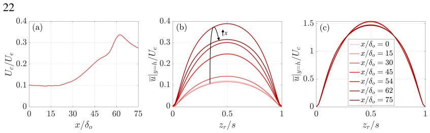
In an accelerating turbulent boundary layer that relaminarizes and then retransitions, riblets with initial s+ = 15.2 and lg+ = 10.5 produce a drag penalty once acceleration begins. The penalty is produced by geometry-determined concentration of viscous shear near the riblet crest. The overlying boundary layer remains similar to the smooth-wall case when scaled with total shear stress evaluated at the groove opening, showing that additional groove drag stays largely decoupled from outer turbulence. At the onset of retransition, spanwise Kelvin-Helmholtz rollers appear near the crests and promote earlier, stronger retransition through interaction with residual near-wall streaks.
What carries the argument
Geometry-driven viscous shear concentration at the riblet crest together with outer-layer scaling by total shear stress at the groove opening, which keeps groove drag decoupled until Kelvin-Helmholtz rollers appear at retransition.
If this is right
- Riblet performance cannot be predicted from zero-pressure-gradient viscous scaling once the flow accelerates.
- The drag penalty remains primarily viscous and geometry-controlled during the relaminarization phase.
- Outer-layer turbulence statistics stay independent of groove details until the start of retransition.
- Kelvin-Helmholtz rollers at the riblet crest interact with residual streaks to advance and intensify retransition.
Where Pith is reading between the lines
- Surface textures intended for vehicles or pipes should be sized differently for phases of flow acceleration rather than using steady-flow optima.
- The observed decoupling implies groove geometry and outer-flow control could be optimized independently in non-equilibrium conditions.
- Similar shear-concentration effects may appear with other riblet-like textures under varying pressure gradients such as those in turbomachinery.
Load-bearing premise
The total shear stress at the groove opening fully sets the scaling for the overlying boundary layer and keeps groove-generated drag decoupled from outer-layer turbulence throughout relaminarization.
What would settle it
An observation or simulation in which Reynolds or dispersive stresses inside the grooves contribute substantially to total drag during relaminarization, or in which outer-layer statistics deviate from smooth-wall scaling when normalized by groove-opening shear stress.
Figures


read the original abstract
Direct numerical simulations of an accelerating turbulent boundary layer (TBL) over a smooth wall and a wall fully covered with streamwise-aligned riblets are performed to investigate drag modulation and its underlying mechanisms. The riblet-scale flow is resolved using an immersed boundary method. Starting from a zero-pressure-gradient (ZPG) TBL at Re=6800, the flow undergoes a threefold freestream acceleration over seventy-five boundary-layer thicknesses, matching the development reported by Warnack and Fernholz (1998), and consequently experiences relaminarization followed by retransition farther downstream. The riblets, defined by a sinusoidal spanwise profile with initial s+=15.2 and lg+=10.5, correspond to near-optimal drag-reducing size in ZPG flows. However, even modest acceleration renders them drag-increasing, showing that the conventional ZPG interpretation based on total-drag viscous scaling does not apply directly in this non-equilibrium flow. During relaminarization, the drag penalty arises primarily from geometry-determined concentration of viscous shear near the riblet crest, with negligible direct Reynolds- and dispersive-stress contributions prior to retransition. Despite the drag increase, the overlying TBL remains statistically similar to the smooth-wall case when scaled with the total shear stress at the groove opening, demonstrating that this shear sets the relevant scaling for the TBL, while the additional drag generated within the grooves remains largely decoupled from the outer-layer turbulence dynamics. This partial decoupling persists until the onset of retransition, when spanwise Kelvin-Helmholtz rollers develop near the riblet crest and promote earlier, stronger retransition through their interaction with the residual near-wall streaks. These findings provide a revised physical picture of riblet performance in non-equilibrium turbulent flows.
Editorial analysis
A structured set of objections, weighed in public.
Referee Report
Summary. The manuscript reports DNS of an accelerating TBL over smooth and riblet walls (starting from ZPG at Re=6800 with threefold freestream acceleration matching Warnack & Fernholz 1998), using IBM to resolve riblet-scale flow. Riblets (sinusoidal, initial s+=15.2, lg+=10.5) that reduce drag in ZPG become drag-increasing under modest acceleration. The penalty is attributed primarily to geometry-driven viscous shear concentration at crests, with negligible Reynolds- and dispersive-stress contributions during relaminarization. Outer-layer TBL statistics remain similar to the smooth case when scaled on total shear at the groove opening, indicating decoupling of intra-groove drag from outer dynamics. Spanwise KH rollers near the crest promote earlier, stronger retransition via interaction with residual streaks.
Significance. If the results hold, the work revises the physical picture of riblet performance in non-equilibrium flows by demonstrating that ZPG viscous scaling does not apply directly and by isolating the viscous crest mechanism with negligible stress contributions until retransition. The DNS enables explicit decomposition of viscous, Reynolds, and dispersive stresses and identification of KH structures, providing mechanism-level insight and falsifiable predictions for riblet behavior under favorable pressure gradients. Direct comparison to independent experimental data strengthens the findings.
major comments (1)
- [Results on statistics and stress decomposition] The decoupling claim—that groove-generated drag remains largely decoupled from outer-layer dynamics so that total shear stress at the groove opening sets the correct scaling for the overlying TBL—is load-bearing for the central interpretation. The manuscript reports statistical similarity in the outer layer, but the mean momentum balance in accelerating flow includes unsteady and pressure-gradient terms; any spanwise variation in dispersive flux or mean velocity at the groove lip could alter the effective boundary condition imposed on the outer flow. A quantitative check (e.g., comparison of wall-normal mean-velocity gradient or integrated momentum flux immediately above the groove opening between riblet and smooth cases) is needed to confirm that the reported similarity is not partial.
minor comments (2)
- [Methods] The riblet geometry is described as sinusoidal with given s+ and lg+ values, but the methods section should explicitly state how these wall-unit sizes are computed from the initial friction velocity and confirm that the immersed-boundary resolution is sufficient to capture the crest shear concentration without numerical artifacts.
- [Figures and captions] Figure captions and axis labels for the stress decomposition plots should clarify whether the viscous, Reynolds, and dispersive contributions are integrated over the full domain or evaluated at specific wall-normal locations to allow direct assessment of their relative magnitudes during relaminarization.
Simulated Author's Rebuttal
We thank the referee for the careful reading and constructive feedback. We address the single major comment below and have incorporated the requested quantitative verification into the revised manuscript.
read point-by-point responses
-
Referee: [Results on statistics and stress decomposition] The decoupling claim—that groove-generated drag remains largely decoupled from outer-layer dynamics so that total shear stress at the groove opening sets the correct scaling for the overlying TBL—is load-bearing for the central interpretation. The manuscript reports statistical similarity in the outer layer, but the mean momentum balance in accelerating flow includes unsteady and pressure-gradient terms; any spanwise variation in dispersive flux or mean velocity at the groove lip could alter the effective boundary condition imposed on the outer flow. A quantitative check (e.g., comparison of wall-normal mean-velocity gradient or integrated momentum flux immediately above the groove opening between riblet and smooth cases) is needed to confirm that the reported similarity is not partial.
Authors: We agree that the presence of unsteady and pressure-gradient terms in the mean momentum balance for accelerating flow requires a more direct verification that the outer-layer similarity is not merely partial. In the revised manuscript we have added explicit comparisons, at multiple streamwise stations during relaminarization, of (i) the wall-normal gradient of the mean streamwise velocity and (ii) the integrated viscous, Reynolds, and dispersive momentum fluxes evaluated immediately above the groove opening (y equal to the riblet crest height). These quantities collapse to within a few percent between the riblet and smooth-wall cases when the outer flow is scaled on the total shear stress at the groove lip. Spanwise variations in dispersive flux at this height remain negligible (<2 % of the total stress) throughout the relaminarization region. These additional diagnostics confirm that the effective boundary condition experienced by the outer layer is indeed set by the groove-opening shear, thereby supporting the decoupling interpretation while acknowledging the extra terms in the momentum balance. revision: yes
Circularity Check
DNS-based claims remain independent of self-referential definitions or fitted predictions
full rationale
The paper reports direct numerical simulations of an accelerating TBL using an immersed-boundary method on riblet geometry, initialized from a ZPG state at Re=6800 and driven by a prescribed freestream acceleration that matches an external experiment (Warnack & Fernholz 1998). All reported quantities—drag penalty, viscous-shear concentration at the crest, statistical similarity when scaled by groove-opening shear stress, and the onset of Kelvin-Helmholtz rollers—are extracted from the computed velocity and stress fields. No central result is obtained by fitting a parameter to a subset of the data and then re-using that parameter as a “prediction,” nor is any scaling relation defined in terms of itself. The decoupling statement is presented as an observation from the simulations rather than an a-priori assumption that closes the derivation. No self-citations appear in the provided text, and no uniqueness theorem or ansatz is imported from prior author work. Consequently the derivation chain does not reduce to its own inputs.
Axiom & Free-Parameter Ledger
free parameters (1)
- riblet spacing and height in wall units
axioms (2)
- standard math Incompressible Navier-Stokes equations govern the flow
- domain assumption Immersed boundary method accurately enforces no-slip on riblet surfaces
Reference graph
Works this paper leans on
-
[1]
A!”, H.2017 Reynolds-number dependence of wall-pressure fluctuations in a pressure-induced turbulent separation bubble.J. Fluid Mech.833, 563–598. A!# R$%&’, W ., D”()*+’,”, R., W +’-, S., K$.#/, M., C)#’-, D., S+’,!”0-, R. D. & H#12)&’(, N. 2025 Experimental characterisation of Kelvin–Helmholtz rollers over riblet surfaces. J. Fluid Mech. 1009, A65. A’,”0...
work page 2017
-
[2]
& K&7, J.1993 Direct numerical simulation of turbulent flow over riblets
C)$&, H., M$&’, P . & K&7, J.1993 Direct numerical simulation of turbulent flow over riblets. J. Fluid Mech. 255, 503–539. C)$&, K.-S.1989 Near-wall structure of a turbulent boundary layer with riblets. J. Fluid Mech.208, 417–458. C)$&, K.-S.1990 E!ects of longitudinal pressure gradients on turbulent drag reduction with riblets. In Turbulence Control by Pa...
work page 1993
-
[3]
G$/,(1”&’, D., H+’,/”0, R. & S&0$5&2), L. 1995 Direct numerical simulation of turbulent flow over a modelled riblet covered surface. J. Fluid Mech.302, 333–376. G$/,(1”&’, D. & T#+’, T. -C. 1998 Secondary flow induced by riblets. J. Fluid Mech.363, 115–151. G0&44&’, K. P ., F#, L. & M$&’, P . 2021 General method for determining the boundary layer thickness ...
work page 1995
-
[4]
K&1(&$(, V ., S”3&7$1$, A., A13&’($’, C., S&//”0$, J. A., B$00”//, G., G#’-$0, A. G., J&7 ´”’”., J. & S$0&+, J.2017 Direct numerical simulation of a self-similar adverse pressure gradient turbulent boundary layer at the verge of separation. J. Fluid Mech.829. K/#7** , S., G#/,’”0, T., M”&’3”, M. & S2)0 ¨$,”0, W .2010 Riblets in a turbulent adverse-pressur...
work page 2017
-
[5]
Mean turbulence structure in the viscous layer.J. Fluid Mech.549, 25–59. M&-’$1, E., B+01)”/”76 , E. & H#01”0, D. 2009 Double-averaging analysis and local flow characterization of near-bed turbulence in gravel-bed channel flows. J. Fluid Mech.618, 279–303. M$,”(1&, D., E’,0&3+1, S., H#12)&’(, N. & C)#’-, D. 2021 Dispersive stresses in turbulent flow over rib...
work page 2009
-
[6]
The boundary layer with relaminarization. J. Fluid Mech.359, 357–381. W&/2$;, D. C.2008 Formulation of the 𝑧↓𝛩turbulence model revisited. AIAA J.46,
work page 2008
-
[7]
J., G+02 ´8+-M+6$0+/, R., H#12)&’(, N
W$’-, J., C+7$!0”2$, C. J., G+02 ´8+-M+6$0+/, R., H#12)&’(, N. & C)#’-, D. 2024 A viscous vortex model for predicting the drag reduction of riblet surfaces. J. Fluid Mech.978, A18. W#, W . & P&$7”//&, U. 2018 E!ects of surface roughness on a separating turbulent boundary layer. J. Fluid Mech.841, 552–580. W#, X. & M$&’, P .2009 Direct numerical simulation...
work page 2024
discussion (0)
Sign in with ORCID, Apple, or X to comment. Anyone can read and Pith papers without signing in.