Effect of startup modes on cold start performance of PEM fuel cells with different cathode flow fields
Pith reviewed 2026-06-30 19:59 UTC · model grok-4.3
The pith
Metal foam flow fields give PEM fuel cells better cold start performance than serpentine fields at constant 0.3 V, with variable current mode offering further gains.
A machine-rendered reading of the paper's core claim, the machinery that carries it, and where it could break.
Core claim
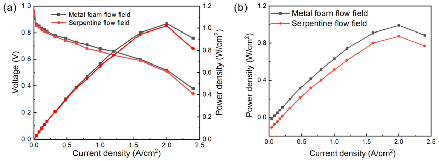
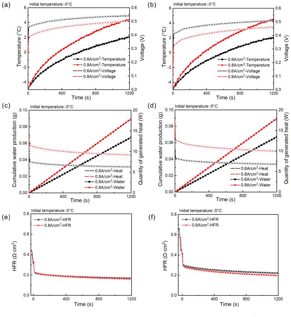
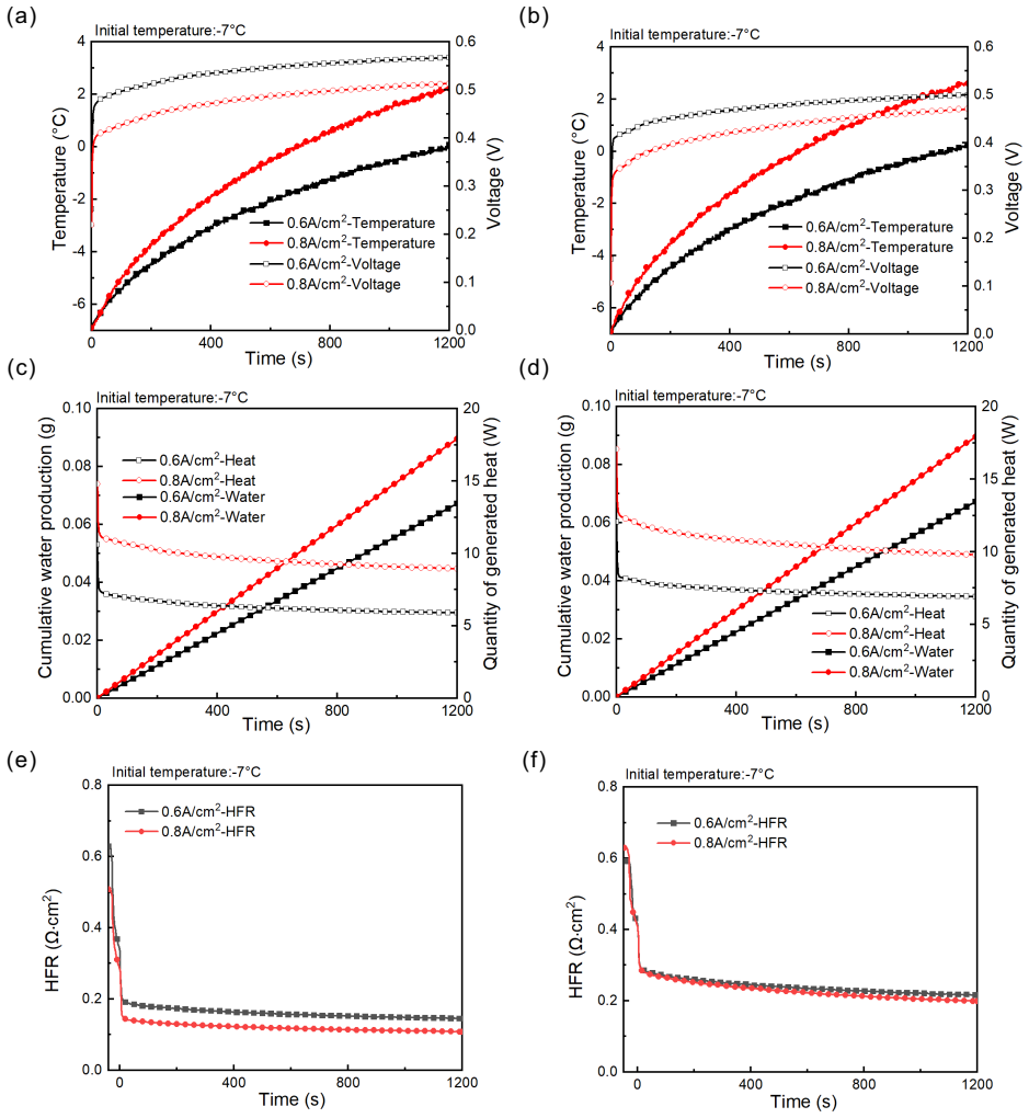
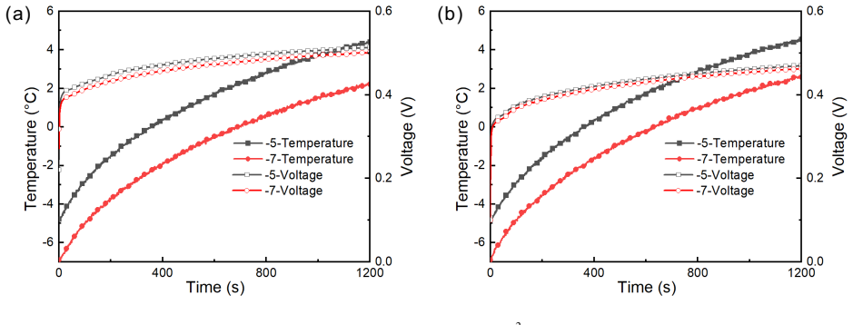
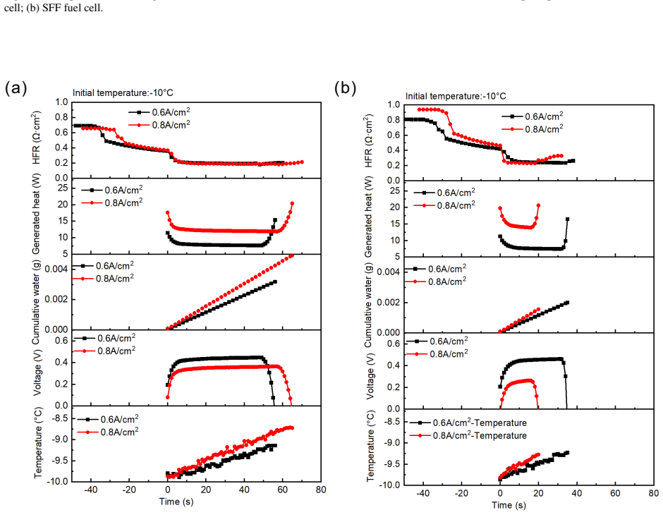
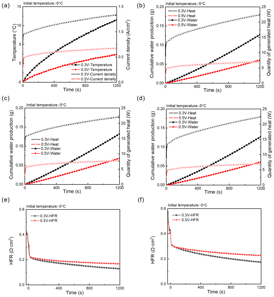
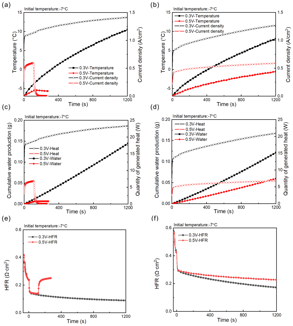
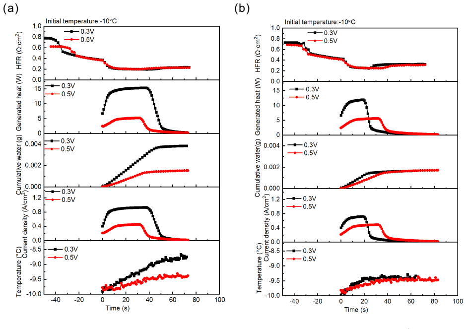
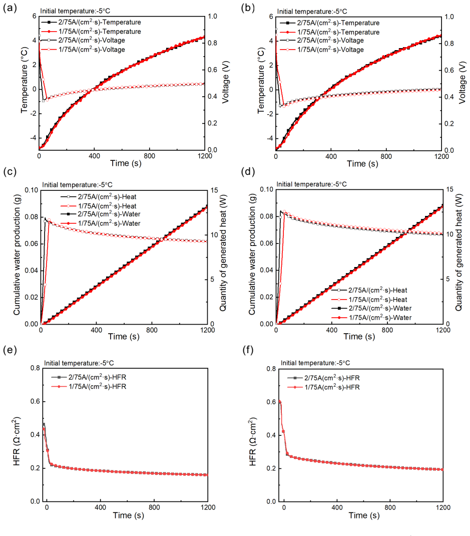
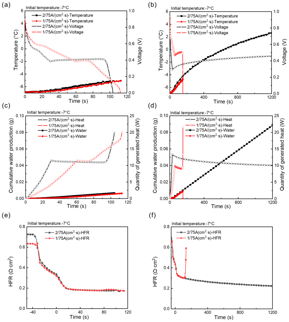
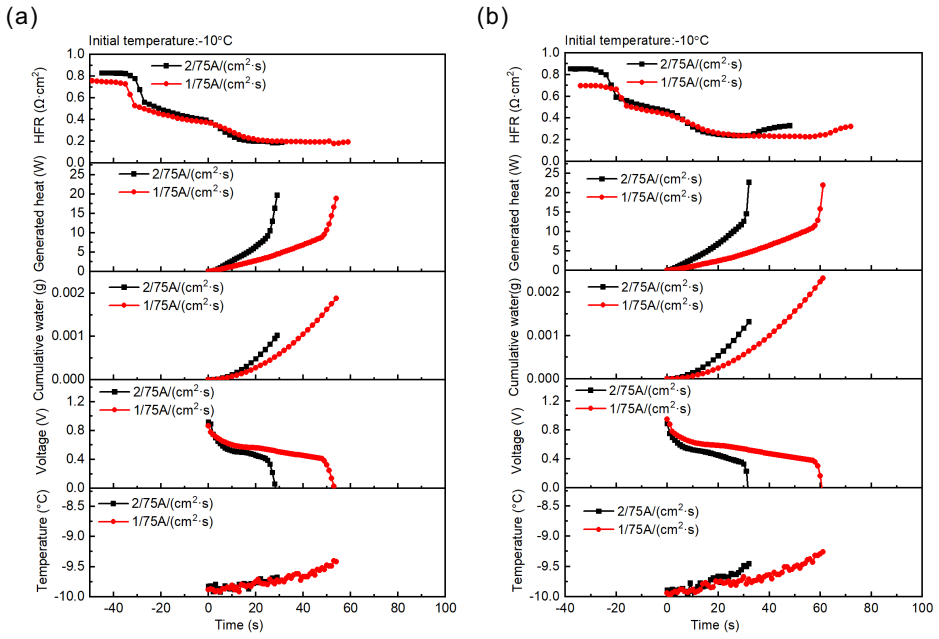
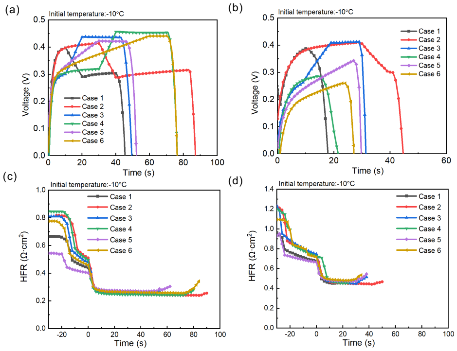
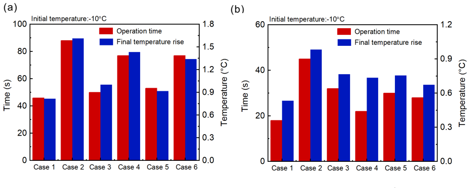
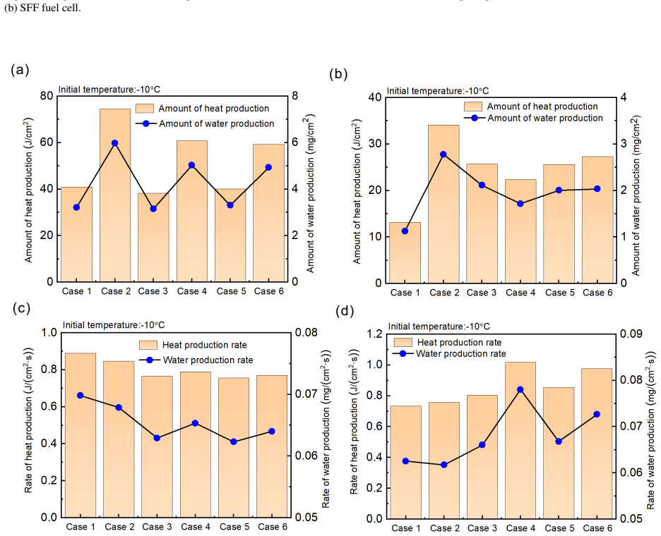
The metal foam flow field (MFFF) PEM fuel cell exhibits superior cold start performance compared to the serpentine flow field (SFF) under constant voltage mode of 0.3 V. A variable current mode developed by considering distinct heat and water production in different phases shows that increasing current density at the unsaturated stage raises the heat production rate and lowers the water production rate, which improves cold start performance of PEMFCs.
What carries the argument
Cathode flow field geometry (metal foam versus serpentine) paired with startup mode (constant current, constant voltage, or variable current), which together set the rates of gas distribution, water removal, heat generation, and ice accumulation.
If this is right
- Lowering voltage and raising current improves cold-start performance across flow-field types.
- The metal foam flow field outperforms the serpentine flow field specifically under constant-voltage startup at 0.3 V.
- Ramping current upward during the unsaturated phase increases heat output relative to water output and shortens time to successful start.
- Performance tests combined with electrochemical characterization can track how flow-field choice and mode selection affect ice formation and recovery.
Where Pith is reading between the lines
- The variable-current profile could be further tuned by testing different ramp rates or trigger points to minimize total startup energy.
- Metal foam advantages in water drainage may reduce the frequency of freeze-thaw damage over many cold starts.
- The same phase-aware current strategy might be tested on other low-temperature electrochemical systems that suffer from product accumulation.
- Adopting these flow fields and modes could lower the auxiliary heating power needed for reliable winter operation of fuel-cell vehicles.
Load-bearing premise
The measured performance gaps between the two flow fields and among the startup modes arise mainly from geometry and mode choice rather than from uncontrolled differences in initial membrane water content or test rig conditions.
What would settle it
Repeating the cold-start experiments on multiple cells that begin with identical membrane water content, catalyst state, and rig temperature would show whether the reported advantages of the metal foam field and variable-current protocol persist.
Figures
read the original abstract
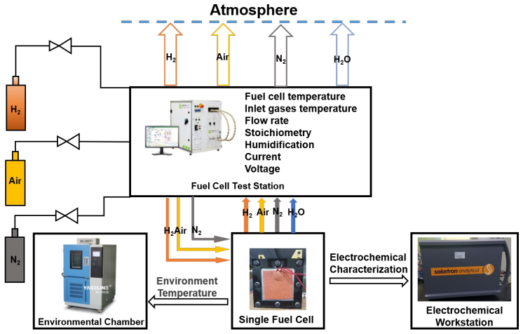
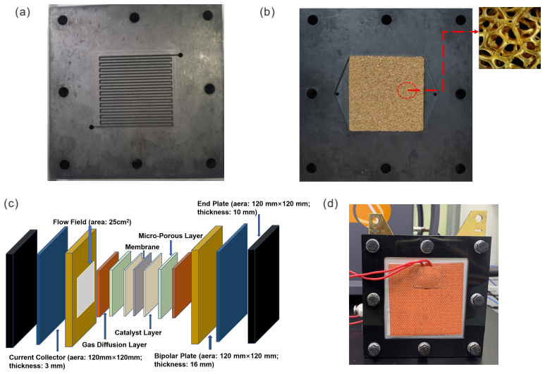
Proton Exchange Membrane Fuel Cell (PEMFC) is widely recognized for its cleanliness and high efficiency, but is still facing challenges in cold environments. At low temperatures, the formation of ice and repeated freezing/thawing cycles may cause cell performance reduction and irreversible degradation. The cathode flow field of PEMFCs has a significant effect on the performance. In contrast to the conventional ``channel-ridge'' flow field, the metal foam has the advantages of excellent pre-distribution of gases and water drainage, which make it a promising candidate for the cold start. This paper examines the cold start of PEMFCs with metal foam flow field (MFFF) and serpentine flow field (SFF), and the influence of constant current mode, constant voltage mode, and ramping current mode is investigated experimentally through performance test and electrochemical characterization. The results show that lowering the voltage and increasing the current can enhance the cold-start performance of fuel cells. The MFFF fuel cell has superior cold start performance compared to the SFF fuel cell under the constant voltage mode of 0.3 V. Furthermore, the variable current mode is developed by considering the distinct properties of heat and water production during various phases, and the results indicate that increasing the current density at the unsaturated stage leads to an elevated rate of heat production and a reduced rate of water production, which can improve the cold start of PEMFCs.
Editorial analysis
A structured set of objections, weighed in public.
Referee Report
Summary. The manuscript experimentally compares cold-start performance of PEM fuel cells with metal foam flow field (MFFF) versus serpentine flow field (SFF) under constant-current, constant-voltage (including 0.3 V), and variable-current startup modes. It claims that MFFF outperforms SFF at 0.3 V constant voltage and that a variable-current protocol improves cold start by raising current density (and thus heat production) while lowering water production during the unsaturated stage.
Significance. If the performance differences are shown to be statistically robust and attributable to flow-field geometry and startup schedule rather than uncontrolled variables, the work could guide practical improvements in PEMFC cold-start reliability for automotive use. The direct experimental comparison of MFFF and SFF is a clear strength, but the lack of replicate statistics and control documentation currently limits the strength of the conclusions.
major comments (2)
- [Abstract/results paragraph] Abstract and results paragraph: the central claims (MFFF superiority at 0.3 V; benefit of variable-current mode) rest on observed performance deltas, yet no information is supplied on number of replicates, error bars, statistical tests, or pre-test controls for initial membrane water content, catalyst state, or rig temperature uniformity. These omissions are load-bearing because the skeptic concern (unmeasured initial-condition variation) cannot be ruled out from the given description.
- [Methods/results] Methods/results: no quantitative details are provided on how initial membrane hydration was equalized across runs (e.g., via EIS, RH soak times, or open-circuit voltage stabilization), which directly affects whether the reported MFFF–SFF gaps can be attributed to flow-field geometry rather than starting-state differences.
minor comments (1)
- [Abstract] Abstract: the phrase 'variable current mode is developed by considering the distinct properties of heat and water production' would be clearer if a brief numerical example of the current schedule (e.g., current density values and transition times) were added.
Simulated Author's Rebuttal
We appreciate the referee's comments on the need for better documentation of experimental controls and statistics. Below we respond to each major comment and indicate the revisions we will make to strengthen the manuscript.
read point-by-point responses
-
Referee: [Abstract/results paragraph] Abstract and results paragraph: the central claims (MFFF superiority at 0.3 V; benefit of variable-current mode) rest on observed performance deltas, yet no information is supplied on number of replicates, error bars, statistical tests, or pre-test controls for initial membrane water content, catalyst state, or rig temperature uniformity. These omissions are load-bearing because the skeptic concern (unmeasured initial-condition variation) cannot be ruled out from the given description.
Authors: We agree that the absence of replicate information and control details weakens the claims. In the original experiments, each startup condition was repeated three times, and we will add error bars (standard deviation) to the performance curves in the revised figures. We will also include a description of the pre-test controls: the cell was purged with dry nitrogen at 60°C for 2 hours prior to cooling to ensure consistent initial membrane water content (verified by stable OCV >0.9 V), and rig temperature was monitored at multiple points for uniformity. No formal statistical tests were applied, but the consistency across replicates supports the observed differences. revision: yes
-
Referee: [Methods/results] Methods/results: no quantitative details are provided on how initial membrane hydration was equalized across runs (e.g., via EIS, RH soak times, or open-circuit voltage stabilization), which directly affects whether the reported MFFF–SFF gaps can be attributed to flow-field geometry rather than starting-state differences.
Authors: We will revise the Methods section to include quantitative details on the initial hydration protocol. All cells underwent a 45-minute open-circuit voltage stabilization under 50% RH at 25°C before cooling to the target subzero temperature, ensuring membrane water content was equalized (OCV stabilized within 5 mV variation). This procedure was identical for MFFF and SFF cells to allow direct comparison of flow field effects. revision: yes
Circularity Check
No circularity: purely experimental comparison with direct measurements
full rationale
The manuscript reports experimental results on PEMFC cold-start performance for MFFF vs. SFF under constant-current, constant-voltage, and variable-current protocols. No equations, models, fitted parameters, or derivations appear in the abstract or described content. Claims rest on measured performance deltas rather than any reduction of outputs to inputs by construction. No self-citations or ansatzes are invoked as load-bearing steps. This is the expected non-finding for a measurement-only study.
Axiom & Free-Parameter Ledger
axioms (1)
- domain assumption Laboratory cold-start conditions and sensor readings accurately reflect the dominant physical processes of ice formation and heat/water balance inside the cell.
Reference graph
Works this paper leans on
-
[1]
A. Pramuanjaroenkij, S. Kakaç, The fuel cell electric vehicles: The highlight review, International Journal of Hydrogen Energy 48 (25) (2023) 9401–9425.doi:10.1016/j.ijhydene.2022.11.103
-
[2]
X. Yang, J. Sun, G. Jiang, S. Sun, Z. Shao, H. Yu, F. Duan, Y . Yang, Experimental study on critical membrane water content of proton exchange membrane fuel cells for cold storage at−50 ◦C, Energies 14 (15) (2021) 4520. doi:10.3390/en14154520
-
[3]
R. Lin, Y . S. Ren, X. W. Lin, Z. H. Jiang, Z. Yang, Y . T. Chang, Investigation of the internal behavior in segmented PEMFCs of different flow fields during cold start process, Energy 123 (2017) 367–377.doi:10. 1016/j.energy.2017.01.138
2017
-
[4]
J. Wang, System integration, durability and reliability of fuel cells: Challenges and solutions, Applied Energy 189 (2017) 460–479.doi:10.1016/j.apenergy.2016.12.083
-
[5]
R. Lin, D. Zhong, S. Lan, R. Guo, Y . Ma, X. Cai, Experimental validation for enhancement of PEMFC cold start performance: Based on the optimization of micro porous layer, Applied Energy 300 (2021) 117306.doi: 10.1016/j.apenergy.2021.117306
-
[6]
Y . Luo, K. Jiao, Cold start of proton exchange membrane fuel cell, Progress in Energy and Combustion Science 64 (2018) 29–61.doi:10.1016/j.pecs.2017.10.003
-
[7]
J. Hou, H. Yu, M. Yang, W. Song, Z. Shao, B. Yi, Reversible performance loss induced by sequential failed cold start of PEM fuel cells, International Journal of Hydrogen Energy 36 (19) (2011) 12444–12451.doi: 10.1016/j.ijhydene.2011.06.100. 22
-
[8]
Z. Yang, K. Jiao, K. Wu, W. Shi, S. Jiang, L. Zhang, Q. Du, Numerical investigations of assisted heating cold start strategies for proton exchange membrane fuel cell systems, Energy 222 (2021).doi:10.1016/j.energy. 2021.119910
-
[9]
Y . Tabe, M. Saito, K. Fukui, T. Chikahisa, Cold start characteristics and freezing mechanism dependence on start-up temperature in a polymer electrolyte membrane fuel cell, Journal of Power Sources 208 (2012) 366– 373.doi:10.1016/j.jpowsour.2012.02.052
-
[10]
C. Zhang, J. Chen, M. Luo, Y . Li, F. Yi, J. Zhou, Z. Zhang, B. Deng, Modelling, validation and analysis of preheating strategy of fuel cell vehicle during subzero cold start, International Journal of Heat and Mass Transfer 220 (2024) 124889.doi:10.1016/j.ijheatmasstransfer.2023.124889
-
[11]
K. Jiao, I. E. Alaefour, G. Karimi, X. Li, Cold start characteristics of proton exchange membrane fuel cells, International Journal of Hydrogen Energy 36 (18) (2011) 11832–11845.doi:10.1016/j.ijhydene.2011. 05.101
-
[12]
P. Chippar, H. Ju, Evaluating cold-start behaviors of end and intermediate cells in a polymer electrolyte fuel cell (PEFC) stack, Solid State Ionics 225 (2012) 85–91.doi:10.1016/j.ssi.2012.02.038
-
[13]
K. Hu, T. Chu, F. Li, B. Wang, Z. Zhang, T. Liu, Effect of different control strategies on rapid cold start-up of a 30-cell proton exchange membrane fuel cell stack, International Journal of Hydrogen Energy 46 (62) (2021) 31788–31797.doi:10.1016/j.ijhydene.2021.07.041
-
[14]
S. Ge, C.-Y . Wang, Characteristics of subzero startup and water/ice formation on the catalyst layer in a polymer electrolyte fuel cell, Electrochimica Acta 52 (14) (2007) 4825–4835.doi:10.1016/j.electacta.2007.01. 038
-
[16]
H. Jiang, L. Xu, H. Struchtrup, J. Li, Q. Gan, X. Xu, Z. Hu, M. Ouyang, Modeling of fuel cell cold start and dimension reduction simplification method, Journal of The Electrochemical Society 167 (4) (2020) 044501. doi:10.1149/1945-7111/ab6ee7
-
[17]
L. Yao, J. Peng, J.-b. Zhang, Y .-j. Zhang, Numerical investigation of cold-start behavior of polymer electrolyte fuel cells in the presence of super-cooled water, International Journal of Hydrogen Energy 43 (32) (2018) 15505– 15520.doi:10.1016/j.ijhydene.2018.06.112
-
[18]
A. Jo, S. Lee, W. Kim, J. Ko, H. Ju, Large-scale cold-start simulations for automotive fuel cells, International Journal of Hydrogen Energy 40 (2) (2015) 1305–1315.doi:10.1016/j.ijhydene.2014.10.020
-
[20]
M. Sundaresan, R. M. Moore, Polymer electrolyte fuel cell stack thermal model to evaluate sub-freezing startup, Journal of Power Sources 145 (2) (2005) 534–545.doi:10.1016/j.jpowsour.2004.12.070
-
[21]
Y . Luo, Q. Guo, Q. Du, Y . Yin, K. Jiao, Analysis of cold start processes in proton exchange membrane fuel cell stacks, Journal of Power Sources 224 (2013) 99–114.doi:10.1016/j.jpowsour.2012.09.089
-
[22]
Y . Ishikawa, H. Hamada, M. Uehara, M. Shiozawa, Super-cooled water behavior inside polymer electrolyte fuel cell cross-section below freezing temperature, Journal of Power Sources 179 (2) (2008) 547–552.doi: 10.1016/j.jpowsour.2008.01.031. 23
-
[23]
A. D. Santamaria, J. Bachman, J. W. Park, Cold-start of parallel and interdigitated flow-field polymer electrolyte membrane fuel cell, Electrochimica Acta 107 (2013) 327–338.doi:10.1016/j.electacta.2013.03.164
-
[24]
W. Gao, Q. Li, K. Sun, R. Chen, Z. Che, T. Wang, Mass transfer and water management in proton exchange membrane fuel cells with a composite foam-rib flow field, International Journal of Heat and Mass Transfer 216 (2023) 124595.doi:10.1016/j.ijheatmasstransfer.2023.124595
-
[25]
Y . Zhu, R. Lin, L. Han, Z. Jiang, D. Zhong, Investigation on cold start of polymer electrolyte membrane fuel cells stacks with diverse cathode flow fields, International Journal of Hydrogen Energy 46 (7) (2021) 5580–5592. doi:10.1016/j.ijhydene.2020.11.021
-
[26]
J. Valentín-Reyes, M. I. León, T. Pérez, T. Romero-Castañón, J. Beltrán, J. R. Flores-Hernández, J. L. Nava, Simulation of an interdigitated flow channel assembled in a proton exchange membrane fuel cell (PEMFC), International Journal of Heat and Mass Transfer 194 (2022) 123026.doi:10.1016/j.ijheatmasstransfer. 2022.123026
-
[27]
Z. Liao, L. Wei, A. M. Dafalla, Z. Suo, F. Jiang, Numerical study of subfreezing temperature cold start of proton exchange membrane fuel cells with zigzag-channeled flow field, International Journal of Heat and Mass Transfer 165 (2021) 120733.doi:10.1016/j.ijheatmasstransfer.2020.120733
-
[28]
H. Hu, X. Xu, N. Mei, C. Li, Numerical study on the influence of waveform channel and related design parameters on the cold start of proton exchange membrane fuel cell, Solid State Ionics 373 (2021) 115794. doi:10.1016/j.ssi.2021.115794
-
[29]
M. Kim, C. Kim, Y . Sohn, Application of metal foam as a flow field for PEM fuel cell stack, Fuel Cells 18 (2) (2018) 123–128.doi:10.1002/fuce.201700180
- [30]
-
[31]
Y . Awin, N. Dukhan, Experimental performance assessment of metal-foam flow fields for proton exchange membrane fuel cells, Applied Energy 252 (2019) 113458.doi:10.1016/j.apenergy.2019.113458
-
[32]
J. G. Carton, A. G. Olabi, Three-dimensional proton exchange membrane fuel cell model: Comparison of double channel and open pore cellular foam flow plates, Energy 136 (2017) 185–195.doi:10.1016/j.energy.2016. 02.010
-
[33]
C.-J. Tseng, B. T. Tsai, Z.-S. Liu, T.-C. Cheng, W.-C. Chang, S.-K. Lo, A PEM fuel cell with metal foam as flow distributor, Energy Conversion and Management 62 (2012) 14–21.doi:10.1016/j.enconman.2012.03.018
-
[35]
E. Afshari, M. Mosharaf-Dehkordi, H. Rajabian, An investigation of the PEM fuel cells performance with partially restricted cathode flow channels and metal foam as a flow distributor, Energy 118 (2017) 705–715. doi:10.1016/j.energy.2016.10.101
-
[36]
D. K. Shin, J. H. Yoo, D. G. Kang, M. S. Kim, Effect of cell size in metal foam inserted to the air channel of polymer electrolyte membrane fuel cell for high performance, Renewable Energy 115 (2018) 663–675.doi: 10.1016/j.renene.2017.08.085
-
[37]
S. Huo, N. J. Cooper, T. L. Smith, J. W. Park, K. Jiao, Experimental investigation on PEM fuel cell cold start behavior containing porous metal foam as cathode flow distributor, Applied Energy 203 (2017) 101–114.doi: 10.1016/j.apenergy.2017.06.028. 24
-
[38]
X. Xie, X. Sun, M. Zhu, G. Zhang, S. Wu, K. Jiao, J. W. Park, Experimental investigation of proton exchange membrane fuel cell with metal foam flow field (2019).doi:10.4271/2019-01-0388
-
[39]
A. A. Amamou, S. Kelouwani, L. Boulon, K. Agbossou, A comprehensive review of solutions and strategies for cold start of automotive proton exchange membrane fuel cells, IEEE Access 4 (2016) 4989–5002.doi: 10.1109/access.2016.2597058
-
[40]
J. Tao, X. Wei, H. Dai, Study on the constant voltage, current and current ramping cold start modes of proton exchange membrane fuel cell, SAE International, 2021.doi:10.4271/2021-01-0746
-
[41]
L. Zang, L. Hao, Numerical study of the cold-start process of PEM fuel cells with different current density operating modes, Journal of Energy Engineering 146 (6) (2020) 04020057.doi:10.1061/(asce)ey. 1943-7897.0000705
-
[43]
F. Jiang, C.-Y . Wang, Potentiostatic start-up of PEMFCs from subzero temperatures, Journal of The Electrochemical Society 155 (7) (2008) B743.doi:10.1149/1.2927381
-
[44]
Y . Yang, T. Ma, B. Du, W. Lin, N. Yao, Investigation on the operating conditions of proton exchange membrane fuel cell based on constant voltage cold start mode, Energies 14 (3) (2021) 660.doi:10.3390/en14030660
-
[46]
F. Jiang, C.-Y . Wang, K. S. Chen, Current ramping: a strategy for rapid start-up of PEMFCs from subfreezing environment, Journal of The Electrochemical Society 157 (3) (2010) B342.doi:10.1149/1.3274820
-
[47]
L. Lei, P. He, P. He, W.-Q. Tao, A comparative study: The effect of current loading modes on the cold start- up process of PEMFC stack, Energy Conversion and Management 251 (2022) 114991.doi:10.1016/j. enconman.2021.114991
work page doi:10.1016/j 2022
-
[48]
Q. Du, B. Jia, Y . Luo, J. Chen, Y . Zhou, K. Jiao, Maximum power cold start mode of proton exchange membrane fuel cell, International Journal of Hydrogen Energy 39 (16) (2014) 8390–8400.doi:10.1016/j.ijhydene. 2014.03.056
-
[49]
Z. Wan, Y . Sun, C. Yang, X. Kong, H. Yan, X. Chen, T. Huang, X. Wang, Experimental performance investigation on the arrangement of metal foam as flow distributors in proton exchange membrane fuel cell, Energy Conversion and Management 231 (2021) 113846.doi:10.1016/j.enconman.2021.113846
-
[50]
D. G. Kang, D. K. Lee, J. M. Choi, D. K. Shin, M. S. Kim, Study on the metal foam flow field with porosity gradient in the polymer electrolyte membrane fuel cell, Renewable Energy 156 (2020) 931–941.doi:10.1016/ j.renene.2020.04.142
2020
-
[51]
X. Chen, C. Yang, Y . Sun, Q. Liu, Z. Wan, X. Kong, Z. Tu, X. Wang, Water management and structure optimization study of nickel metal foam as flow distributors in proton exchange membrane fuel cell, Applied Energy 309 (2022) 118448.doi:10.1016/j.apenergy.2021.118448
-
[52]
K. Tajiri, Y . Tabuchi, F. Kagami, S. Takahashi, K. Yoshizawa, C.-Y . Wang, Effects of operating and design parameters on pefc cold start, Journal of Power Sources 165 (1) (2007) 279–286.doi:10.1016/j.jpowsour. 2006.12.017
-
[53]
X.-Z. Yuan, S. Zhang, J. C. Sun, H. Wang, A review of accelerated conditioning for a polymer electrolyte membrane fuel cell, Journal of Power Sources 196 (22) (2011) 9097–9106.doi:10.1016/j.jpowsour.2011. 06.098. 25
-
[54]
M. M. Taghiabadi, M. Zhiani, V . Silva, Effect of mea activation method on the long-term performance of pem fuel cell, Applied Energy 242 (2019) 602–611.doi:10.1016/j.apenergy.2019.03.157
-
[55]
X. Xie, G. Zhang, J. Zhou, K. Jiao, Experimental and theoretical analysis of ionomer/carbon ratio effect on pem fuel cell cold start operation, International Journal of Hydrogen Energy 42 (17) (2017) 12521–12530. doi:10.1016/j.ijhydene.2017.02.183
-
[56]
X. Xie, R. Wang, K. Jiao, G. Zhang, J. Zhou, Q. Du, Investigation of the effect of micro-porous layer on pem fuel cell cold start operation, Renewable Energy 117 (2018) 125–134.doi:10.1016/j.renene.2017.10.039
-
[57]
D. D. Boettner, G. Paganelli, Y . G. Guezennec, G. Rizzoni, M. J. Moran, Proton exchange membrane fuel cell system model for automotive vehicle simulation and control, Journal of Energy Resources Technology 124 (1) (2002) 7.doi:10.1115/1.1447927
-
[58]
N. J. Cooper, T. Smith, A. D. Santamaria, J. W. Park, Experimental optimization of parallel and interdigitated PEMFC flow-field channel geometry, International Journal of Hydrogen Energy 41 (2) (2016) 1213–1223.doi: 10.1016/j.ijhydene.2015.11.153
-
[59]
G. M. Rios, J. Schirmer, C. Gentner, J. Kallo, Efficient thermal management strategies for cold starts of a proton exchange membrane fuel cell system, Applied Energy 279 (2020) 115813.doi:10.1016/j.apenergy.2020. 115813
-
[60]
R. Lin, X. Lin, Y . Weng, Y . Ren, Evolution of thermal drifting during and after cold start of proton exchange membrane fuel cell by segmented cell technology, International Journal of Hydrogen Energy 40 (23) (2015) 7370–7381.doi:10.1016/j.ijhydene.2015.04.045
-
[61]
H. Huang, Y . Zhou, H. Deng, X. Xie, Q. Du, Y . Yin, K. Jiao, Modeling of high temperature proton exchange membrane fuel cell start-up processes, International Journal of Hydrogen Energy 41 (4) (2016) 3113–3127. doi:10.1016/j.ijhydene.2015.12.134
-
[62]
Y . Ishikawa, M. Shiozawa, M. Kondo, K. Ito, Theoretical analysis of supercooled states of water generated below the freezing point in a pefc, International Journal of Heat and Mass Transfer 74 (2014) 215–227.doi: 10.1016/j.ijheatmasstransfer.2014.03.038
-
[63]
Z. Wan, H. Chang, S. Shu, Y . Wang, H. Tang, A review on cold start of proton exchange membrane fuel cells, Energies 7 (5) (2014) 3179–3203.doi:10.3390/en7053179
-
[64]
G. Gwak, H. Ju, A rapid start-up strategy for polymer electrolyte fuel cells at subzero temperatures based on control of the operating current density, International Journal of Hydrogen Energy 40 (35) (2015) 11989–11997. doi:10.1016/j.ijhydene.2015.05.179
-
[65]
Y . Wang, P. P. Mukherjee, J. Mishler, R. Mukundan, R. L. Borup, Cold start of polymer electrolyte fuel cells: Three-stage startup characterization, Electrochimica Acta 55 (8) (2010) 2636–2644.doi:10.1016/ j.electacta.2009.12.029. 26
2010
discussion (0)
Sign in with ORCID, Apple, or X to comment. Anyone can read and Pith papers without signing in.