A Reciprocity-Based Signal Compensation Framework for Ultrasonic Backscatter Measurements in Heterogeneous Scattering Media
Pith reviewed 2026-05-22 02:45 UTC · model grok-4.3
The pith
Reciprocity-based compensation removes shared depth bias from opposing ultrasonic backscatter profiles in heterogeneous anisotropic materials.
A machine-rendered reading of the paper's core claim, the machinery that carries it, and where it could break.
Core claim
The dominant through-thickness propagation bias in ultrasonic backscatter measurements contains a shared component between opposing inspection directions that can be isolated by anchor-based fitting in the logarithmic amplitude domain and used to compensate measured profiles, thereby reconciling opposing-face data without distorting genuine local microstructural scattering variations.
What carries the argument
The cross-directional compensation method, which isolates a shared distance-dependent baseline from opposing-face signals using anchor-based fitting in the log-amplitude domain and applies it to remove propagation bias.
If this is right
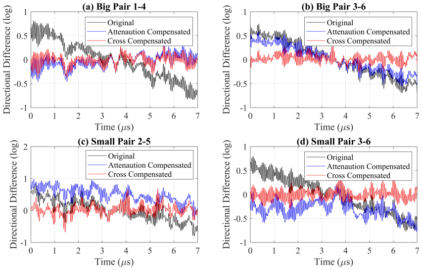
- Opposing-face backscatter profiles become more consistent after compensation, with mean standard deviation of directional mismatch falling from 0.367 to 0.120.
- The mean absolute fitted gradient of the mismatch profile drops from 0.171 to 0.0067.
- The method outperforms conventional attenuation compensation on the tested Ti-6Al-4V samples.
- Local direction-dependent scattering variations remain preserved in the compensated signals.
Where Pith is reading between the lines
- The approach could extend to other reciprocal wave measurements such as acoustic emission or seismic backscatter where opposing-path data are available.
- It offers a route to improve depth-resolved microstructure maps in non-destructive evaluation of textured alloys.
- A direct test would apply the compensation to synthetic data generated from known heterogeneous scattering models and check recovery of the input depth profile.
Load-bearing premise
The dominant through-thickness propagation bias contains a shared component between opposing inspection directions that can be isolated by anchor-based fitting without distorting genuine local microstructural scattering information.
What would settle it
Controlled experiments on samples with independently verified local scattering properties where the compensated opposing-face profiles still exhibit large residual mismatch or where known depth variations are altered after compensation.
Figures




read the original abstract
Ultrasonic backscatter measurements are widely used for microstructural characterisation. However, in materials containing strong anisotropy and spatial heterogeneity, the interpretation of backscatter signals becomes challenging because distance-dependent propagation effects can obscure genuine microstructural variations across depth. In this paper, a cross-directional compensation method is presented for ultrasonic backscatter measurements acquired from opposing inspection surfaces. The method exploits the reciprocal constraint that the dominant through-thickness propagation bias should contain a shared component between opposing inspection directions. A shared distance-dependent baseline is estimated in the logarithmic amplitude domain using an anchor-based fitting approach and subsequently used to compensate the measured backscatter profiles with depth. The method is demonstrated on two macrozone-containing Ti--6Al--4V samples, where conventional attenuation-based compensation is shown to be insufficient to consistently reconcile opposing-face backscatter profiles. Across six opposing-face signal pairs, the proposed method reduces the mean standard deviation of the directional mismatch profile from $0.367$ to $0.120$ and the mean absolute fitted gradient from $0.171$ to $0.0067$, outperforming conventional attenuation compensation. These results demonstrate that reciprocity-based compensation can reduce propagation-related bias while preserving local direction-dependent scattering variations, providing a practical signal-normalisation framework for backscatter analysis in heterogeneous anisotropic materials.
Editorial analysis
A structured set of objections, weighed in public.
Referee Report
Summary. The manuscript presents a reciprocity-based signal compensation framework for ultrasonic backscatter measurements in heterogeneous scattering media. It proposes a cross-directional method that exploits the reciprocal constraint between opposing inspection directions to estimate and remove a shared distance-dependent propagation bias using anchor-based fitting in the logarithmic amplitude domain. Demonstrated on two macrozone-containing Ti-6Al-4V samples, the method reduces the mean standard deviation of the directional mismatch profile from 0.367 to 0.120 and the mean absolute fitted gradient from 0.171 to 0.0067 across six opposing-face signal pairs, outperforming conventional attenuation compensation while preserving local direction-dependent scattering variations.
Significance. If the central assumption holds, the framework offers a practical normalization approach for backscatter analysis in anisotropic heterogeneous materials, enabling more reliable interpretation of local microstructural variations by mitigating through-thickness propagation bias. The quantitative experimental results on real Ti-6Al-4V samples with macrozones provide concrete, falsifiable metrics of improvement over standard attenuation compensation, which is a strength for applied ultrasonics research.
major comments (1)
- [Cross-directional compensation method description] Cross-directional compensation method (anchor-based fitting description): The central claim that the shared baseline isolates the dominant propagation bias without distorting genuine local direction-dependent scattering information is load-bearing but not internally ruled out. In macrozone-containing Ti-6Al-4V, the fitting anchors could capture spatially varying backscatter from grain clusters rather than pure propagation; if so, the reported drops (std dev 0.367→0.120, gradient 0.171→0.0067) would partly reflect smoothing of real variations. The six-pair comparison alone does not address this risk via independent microstructural validation or sensitivity tests on anchor selection.
minor comments (2)
- [Abstract] Abstract: The reported metrics lack accompanying uncertainty estimates, number of independent measurements per pair, or details on how the shared baseline fit parameters were optimized, which would strengthen the quantitative claims.
- [Validation] Validation section: Conventional attenuation compensation is stated to be insufficient, but the specific attenuation model, frequency range, and implementation details used for comparison are not fully specified, hindering direct reproduction.
Simulated Author's Rebuttal
We thank the referee for their constructive feedback on our manuscript. Below we provide a point-by-point response to the single major comment, focusing on the technical substance of the concern.
read point-by-point responses
-
Referee: Cross-directional compensation method (anchor-based fitting description): The central claim that the shared baseline isolates the dominant propagation bias without distorting genuine local direction-dependent scattering information is load-bearing but not internally ruled out. In macrozone-containing Ti-6Al-4V, the fitting anchors could capture spatially varying backscatter from grain clusters rather than pure propagation; if so, the reported drops (std dev 0.367→0.120, gradient 0.171→0.0067) would partly reflect smoothing of real variations. The six-pair comparison alone does not address this risk via independent microstructural validation or sensitivity tests on anchor selection.
Authors: The method is founded on the reciprocity principle for through-thickness propagation: attenuation, diffraction, and other path-dependent effects are identical for opposing directions along the same material path and therefore appear as a shared baseline in the log-amplitude domain. Local scattering from macrozones is direction-dependent because grain orientations relative to the incident wave differ when the inspection direction is reversed; these contributions are therefore not reciprocal and remain as deviations from the fitted baseline. The anchor-based fit is constructed to capture only the common monotonic trend, leaving direction-specific fluctuations intact. The experimental results show that after compensation the directional mismatch is reduced while local peaks and troughs that differ between the two faces are retained, which would not occur if genuine scattering variations were being removed. The six independent opposing-face pairs constitute repeated tests of this separation on real macrozone-containing material. We acknowledge that correlation with independent microstructural maps (e.g., EBSD) would constitute additional supporting evidence, but the internal consistency of the reciprocity argument together with the quantitative improvement over conventional attenuation compensation already addresses the risk of over-smoothing. revision: no
Circularity Check
No significant circularity; derivation remains self-contained
full rationale
The paper presents a reciprocity-based compensation method that estimates a shared distance-dependent baseline via anchor-based fitting in the log-amplitude domain and applies it to opposing-face backscatter profiles. Validation metrics (mean standard deviation of directional mismatch reduced from 0.367 to 0.120, mean absolute fitted gradient from 0.171 to 0.0067) are computed directly on the post-compensation experimental profiles from six opposing-face pairs in Ti-6Al-4V samples and compared against conventional attenuation compensation. No load-bearing step reduces by construction to its own inputs, fitted parameters, or self-citation chains; the fitting serves as a practical normalization step whose outcome is independently assessed on real data without the metrics being tautological residuals of the fit itself. The central empirical claim therefore retains independent content.
Axiom & Free-Parameter Ledger
free parameters (1)
- Shared baseline fit parameters
axioms (1)
- domain assumption The dominant through-thickness propagation bias contains a shared component between opposing inspection directions.
Lean theorems connected to this paper
-
IndisputableMonolith/Cost/FunctionalEquation.leanwashburn_uniqueness_aczel unclear?
unclearRelation between the paper passage and the cited Recognition theorem.
A shared distance-dependent baseline is estimated in the logarithmic amplitude domain using an anchor-based fitting approach
-
IndisputableMonolith/Foundation/ArithmeticFromLogic.leanembed_add unclear?
unclearRelation between the paper passage and the cited Recognition theorem.
The method exploits the reciprocal constraint that the dominant through-thickness propagation bias should contain a shared component between opposing inspection directions
What do these tags mean?
- matches
- The paper's claim is directly supported by a theorem in the formal canon.
- supports
- The theorem supports part of the paper's argument, but the paper may add assumptions or extra steps.
- extends
- The paper goes beyond the formal theorem; the theorem is a base layer rather than the whole result.
- uses
- The paper appears to rely on the theorem as machinery.
- contradicts
- The paper's claim conflicts with a theorem or certificate in the canon.
- unclear
- Pith found a possible connection, but the passage is too broad, indirect, or ambiguous to say the theorem truly supports the claim.
Reference graph
Works this paper leans on
-
[1]
ZebangZheng,DanielS.Balint,andFionnP.E.Dunne. Discretedislocationandcrystalplasticityanalysesofloadsheddinginpolycrystalline titanium alloys.International Journal of Plasticity, 87(September):15–31, 2016. ISSN 07496419. doi: 10.1016/j.ijplas.2016.08.009
-
[2]
YilunXu,SudhaJoseph,PhaniKaramched,KateFox,DavidRugg,FionnP.E.Dunne,andDavidDye. Predictingdwellfatiguelifeintitanium alloys using modelling and experiment.Nature Communications, 11(1):1–13, 2020. ISSN 20411723. doi: 10.1038/s41467-020-19470-w
-
[3]
ZhihongWu,HongchaoKou,NanaChen,ZhichengXi,JiangkunFan,BinTang,andJinshanLi. Recentdevelopmentsincolddwellfatigueof titanium alloys for aero-engine applications: a review.Journal of Materials Research and Technology, 20:469–484, 9 2022. ISSN 22387854. doi: 10.1016/j.jmrt.2022.07.094. 15
-
[4]
M. Huang, P. Huthwaite, S. I. Rokhlin, and M. J. S. Lowe. Finite-element and semi-analytical study of elastic wave propagation in strongly scattering polycrystals.Proceedings of the Royal Society A: Mathematical, Physical and Engineering Sciences, 478, 2022. ISSN 14712946. doi: 10.1098/rspa.2021.0850
-
[5]
Kalkowski, Ming Huang, Michael J.S
Yuan Liu, Michał K. Kalkowski, Ming Huang, Michael J.S. Lowe, Vykintas Samaitis, Vaidotas Cic˙enas, and Andreas Schumm. Can ultrasound attenuation measurement be used to characterise grain statistics in castings?Ultrasonics, 115, 2021. ISSN 0041624X. doi: 10.1016/j.ultras.2021.106441
-
[6]
Rodríguez, Heriberto Granados Becerra, and Jin-Yeon Kim
Alberto Ruiz, Vania M. Rodríguez, Heriberto Granados Becerra, and Jin-Yeon Kim. Ultrasonic characterization of microstructural changes due to static recrystallization and grain growth in inconel 625 and inconel 718 superalloys.Ultrasonics, 142:107383, 2024. doi: 10.1016/j.ultras.2024.107383
-
[7]
BLan,M.J.S.Lowe,andF.P.E.Dunne. Experimentalandcomputationalstudiesofultrasoundwavepropagationinhexagonalclose-packed polycrystals for texture detection.Acta Materialia, 63:107–122, 2014. ISSN 1359-6454. doi: 10.1016/j.actamat.2013.10.012
-
[8]
Ben Britton, Tea-Sung Jun, Weimin Gan, Michael Hofmann, Fionn P.E
Bo Lan, T. Ben Britton, Tea-Sung Jun, Weimin Gan, Michael Hofmann, Fionn P.E. Dunne, and Michael J.S. Lowe. Direct volumetric measurementofcrystallographictextureusingacousticwaves.Acta Materialia,159:384–394,2018. ISSN13596454. doi:10.1016/j.actamat. 2018.08.037
-
[9]
Modeling Ultrasonic Microstructural Noise in Titanium Alloys
F J Margetan and R B Thompson. Modeling Ultrasonic Microstructural Noise in Titanium Alloys. InReview of Progress in Quantitative Nondestructive Evaluation, volume 12, pages 1735–1742, 1993
work page 1993
-
[10]
F.J.Margetan,R.B.Thompson,andI.Yalda-Mooshabad. BackscatteredMicrostructuralNoiseinUltrasonicToneburstInspections.Journal of Nondestructive Evaluation, 13(3):111–136, 1994. ISSN 1573-4862. doi: 10.1007/BF00728250
-
[11]
Yuan Liu, Anton Van Pamel, Peter B. Nagy, and Peter Cawley. Investigation of ultrasonic backscatter using three-dimensional finite element simulations.The Journal of the Acoustical Society of America, 145(3):1584–1595, 2019. ISSN 0001-4966. doi: 10.1121/1.5094783
-
[12]
Turner, Yongfeng Song, and Xiongbing Li
Yangguang Bu, Xiling Liu, Joseph A. Turner, Yongfeng Song, and Xiongbing Li. Grain size evaluation with time-frequency ultrasonic backscatter.NDT & E International, 117:102369, 2021. doi: 10.1016/j.ndteint.2020.102369
-
[13]
WeiWang,JieZhang,andPaulD.Wilcox. Metallicmaterialmicrostructuregrainsizemeasurementsfrombackscatteredultrasonicarraydata using full matrix capture.NDT & E International, 149:103251, 2025. doi: 10.1016/j.ndteint.2024.103251
-
[14]
BohanLiu,MingHuang,DehanZhang,andXudongYu. Ultrasonicbackscatteringmethodforcharacterizingthenon-uniformmicrostructure of polycrystals.International Journal of Mechanical Sciences, 259:110831, 2025. doi: 10.1016/j.ijmecsci.2025.110831
-
[15]
M. A. Cuddihy, A. Stapleton, S. Williams, and F. P.E. Dunne. On cold dwell facet fatigue in titanium alloy aero-engine components. International Journal of Fatigue, 97:177–189, 2017. ISSN 01421123. doi: 10.1016/j.ijfatigue.2016.11.034
-
[16]
Yang Liu and Fionn P E Dunne. The Mechanistic Link between Macrozones (MTRs) and Dwell Fatigue in Titanium Alloys.International Journal of Fatigue, 142(September 2020):105971, 2021. ISSN 0142-1123. doi: 10.1016/j.ijfatigue.2020.105971
-
[17]
W. Y. Yeoh, B. Lan, and M. J. S. Lowe. Investigation of the influence of macrozones in titanium alloys on the propagation and scattering of ultrasound.Proceedings of the Royal Society A: Mathematical, Physical and Engineering Sciences, 479, 9 2023. ISSN 1364-5021. doi: 10.1098/rspa.2023.0176. URLhttps://royalsocietypublishing.org/doi/10.1098/rspa.2023.0176
-
[18]
O. I. Lobkis, L. Yang, J. Li, and S. I. Rokhlin. Directional ultrasonic backscattering in polycrystals with elongated grains.AIP Conference Proceedings, 1430(31):1389–1396, 2012. ISSN 0094243X. doi: 10.1063/1.4716379
-
[19]
L. Yang, J. Li, and S. I. Rokhlin. Ultrasonic scattering in polycrystals with orientation clusters of orthorhombic crystallites.Wave Motion, 50 (8):1283–1302, 2013. ISSN 01652125. doi: 10.1016/j.wavemoti.2013.06.003
-
[20]
Pilchak, Jia Li, and Stanislav I
Adam L. Pilchak, Jia Li, and Stanislav I. Rokhlin. Quantitative comparison of microtexture in near-alpha titanium measured by ultrasonic scattering and electron backscatter diffraction.Metallurgical and Materials Transactions A: Physical Metallurgy and Materials Science, 45 (10):4679–4697, 2014. ISSN 10735623. doi: 10.1007/s11661-014-2367-1
-
[21]
S. I. Rokhlin, G. Sha, J. Li, and A. L. Pilchak. Inversion methodology for ultrasonic characterization of polycrystals with clusters of preferentially oriented grains.Ultrasonics, 115(March), 2021. ISSN 0041624X. doi: 10.1016/j.ultras.2021.106433
-
[22]
W. Y. Yeoh, B. Lan, and M. J. S. Lowe. Representative microstructures for two-dimensional computational studies of ultrasonic wave propagationintitaniumalloys.Proceedings of the Royal Society A: Mathematical, Physical and Engineering Sciences,481(2323):20240776,
-
[23]
doi: 10.1098/rspa.2024.0776
-
[24]
Peter H. Rogers and A. L. Van Buren. An exact expression for the Lommel-diffraction correction integral.The Journal of the Acoustical Society of America, 55(4):724–728, 1974. ISSN 0001-4966. doi: 10.1121/1.1914589
-
[25]
Fei Zeng, Sean R Agnew, Babak Raeisinia, and Ganapati R Myneni. Ultrasonic Attenuation Due to Grain Boundary Scattering in Pure Niobium.Journal of Nondestructive Evaluation, 29:93–103, 2010. doi: 10.1007/s10921-010-0068-2
-
[26]
Detectability of Small Flaws in Advanced Engine Alloys
Frank J Margetan, R Bruce Thompson, and Y Kim Han. Detectability of Small Flaws in Advanced Engine Alloys. Technical report, Iowa State University, 1993
work page 1993
-
[27]
L.Yang,J.Li,O.I.Lobkis,andS.I.Rokhlin. UltrasonicPropagationandScatteringinDuplexMicrostructureswithApplicationtoTitanium Alloys.Journal of Nondestructive Evaluation, 31:270–283, 2012. doi: 10.1007/s10921-012-0141-0
-
[28]
Lee R. Dice. Measures of the amount of ecologic association between species.Ecology, 26(3):297–302, 1945
work page 1945
-
[29]
Abdel Aziz Taha and Allan Hanbury. Metrics for evaluating 3d medical image segmentation.IEEE Transactions on Medical Imaging, 34 (11):2367–2380, 2015
work page 2015
-
[30]
Aurélien Baelde, Jérôme Laurent, Pierre Millien, Richard Coulette, Warida Ben Khalifa, Frédéric Jenson, Fan Sun, Mathias Fink, and Claire Prada. Effect of microstructural elongation on backscattered field: Intensity measurement and multiple scattering estimation with a linear transducer array.Ultrasonics, 82:379–389, 2018. ISSN 0041624X. doi: 10.1016/j.ul...
-
[31]
James L. Blackshire, Jeong K. Na, and Kevin Daugherty. Coherent ultrasonic backscatter within a textured titanium alloy.AIP Conference Proceedings, 2102, 2019. ISSN 15517616. doi: 10.1063/1.5099725. 16
discussion (0)
Sign in with ORCID, Apple, or X to comment. Anyone can read and Pith papers without signing in.