Laser fractional frequency instability at mathbf{4times 10⁻¹⁷} with a room temperature optical reference cavity
Pith reviewed 2026-06-27 23:59 UTC · model grok-4.3
The pith
A 68 cm room-temperature optical cavity achieves 4×10^{-17} laser fractional frequency instability and 12 mHz linewidth.
A machine-rendered reading of the paper's core claim, the machinery that carries it, and where it could break.
Core claim
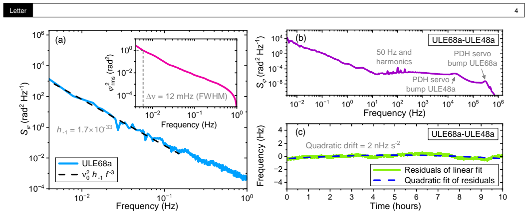
We demonstrate laser fractional frequency instability at 4×10^{-17} and laser frequency linewidth of 12 mHz full width at half maximum, employing a 68 cm long optical reference cavity operating at room temperature. To the best of our knowledge, both frequency instability and linewidth are the lowest ever reported for a room temperature system.
What carries the argument
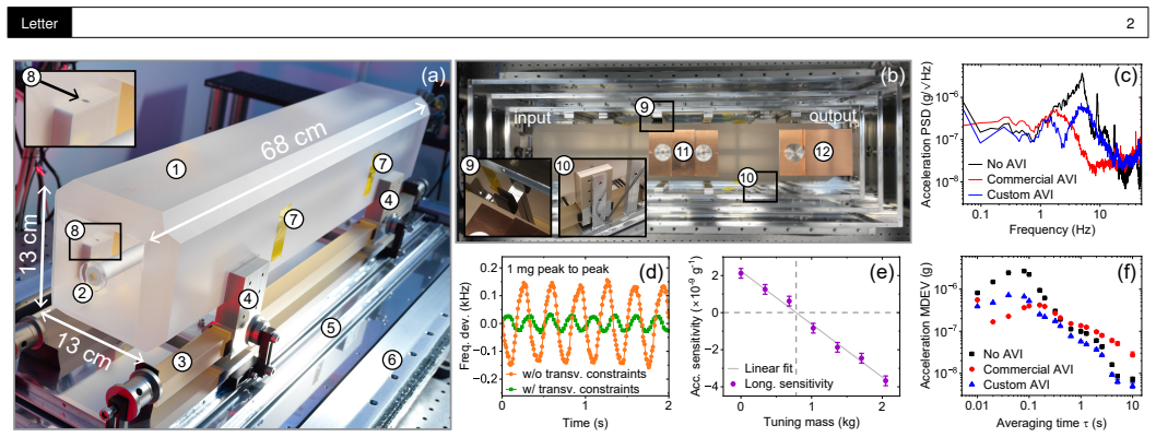
A 68 cm long optical reference cavity operating at room temperature, used to stabilize the laser via its length stability.
If this is right
- State-of-the-art frequency stability becomes achievable without cryogenic systems.
- Spectral purity at the 12 mHz level is possible in room-temperature setups.
- Ultrastable lasers can be deployed by a broader range of users in optical frequency metrology.
- Measurement speed and stability limits for optical frequency standards improve without specialized infrastructure.
Where Pith is reading between the lines
- Portable or field-deployable ultrastable lasers may now be feasible without large cryogenic setups.
- The result narrows the performance gap between room-temperature and cryo-stabilized cavities, potentially simplifying next-generation optical clock designs.
- Further work could test whether similar cavities maintain this stability when integrated into smaller or mobile systems.
Load-bearing premise
The reported instability and linewidth are not limited by unaccounted systematic effects or measurement artifacts, and the cavity truly operates at ambient room temperature without undisclosed stabilization techniques.
What would settle it
An independent frequency comparison against a second, separately verified room-temperature reference that yields instability above 4×10^{-17} or linewidth above 12 mHz would falsify the claim.
Figures
read the original abstract
Ultrastable lasers play a key role in optical frequency metrology, setting measurement speed and ultimately impacting both stability and accuracy of optical frequency standards. Here we demonstrate laser fractional frequency instability at ${4}\times10^{-17}$ and laser frequency linewidth of $12\,$mHz full width at half maximum, employing a 68 cm long optical reference cavity operating at room temperature. To the best of our knowledge, both frequency instability and linewidth are the lowest ever reported for a room temperature system. This work highlights that state-of-the-art frequency stability and spectral purity are achievable at room temperature, making them accessible to a broader range of users.
Editorial analysis
A structured set of objections, weighed in public.
Referee Report
Summary. The manuscript reports an experimental demonstration of ultrastable laser performance using a 68 cm room-temperature optical reference cavity, achieving a fractional frequency instability of 4×10^{-17} and a linewidth of 12 mHz FWHM. These values are stated to be the lowest reported for any room-temperature system, with the work emphasizing accessibility without cryogenic cooling.
Significance. If the reported performance is substantiated by the full measurement data and error analysis, the result would establish that state-of-the-art stability and spectral purity are attainable at ambient temperature. This could broaden the use of ultrastable lasers in optical frequency metrology by removing the need for specialized cryogenic infrastructure.
minor comments (2)
- The abstract and introduction should explicitly reference the specific prior room-temperature results (with citations and numerical values) that are being surpassed, to allow readers to verify the 'lowest ever reported' claim without external lookup.
- Figure captions and methods sections should include the exact averaging times, integration methods, and reference laser details used to extract the 4×10^{-17} instability and 12 mHz linewidth, ensuring reproducibility from the presented data.
Simulated Author's Rebuttal
We thank the referee for the positive assessment of our work, the recognition of its potential impact, and the recommendation for minor revision. No specific major comments were provided in the report.
Circularity Check
No significant circularity
full rationale
This is an experimental measurement report demonstrating achieved laser frequency instability and linewidth with a room-temperature cavity. No derivation chain, equations, fitted parameters renamed as predictions, or self-citation load-bearing steps exist in the provided text or abstract. The central claims rest on direct experimental results rather than any reduction to prior inputs by construction, satisfying the default expectation of no circularity for such papers.
Axiom & Free-Parameter Ledger
Reference graph
Works this paper leans on
-
[1]
A. D. Ludlow, M. M. Boyd, J. Y e,et al., Rev. Mod. Phys.87, 637 (2015)
2015
-
[2]
R. V . Pound, Rev. Sci. Instruments17, 490 (1946)
1946
-
[3]
R. W. P . Drever, J. L. Hall, F . V . Kowalski,et al., Appl. Phys. B31, 97 (1983)
1983
-
[4]
Nazarova, F
T . Nazarova, F . Riehle, and U. Sterr, Appl. Phys. B83, 531 (2006)
2006
-
[5]
L. Chen, J. L. Hall, J. Y e,et al., Phys. Rev. A74, 053801 (2006)
2006
-
[6]
Numata, A
K. Numata, A. Kemery , and J. Camp, Phys. Rev. Lett.93, 250602 (2004)
2004
-
[7]
Y . Y . Jiang, A. D. Ludlow, N. D. Lemke,et al., Nat. Photonics5, 158 (2011)
2011
-
[8]
Kessler, T
T . Kessler, T . Legero, and U. Sterr, J. Opt. Soc. Am. B29, 178 (2012)
2012
-
[9]
Wiens, Q.-F
E. Wiens, Q.-F . Chen, I. Ernsting,et al., Opt. Lett.39, 3242 (2014)
2014
-
[10]
D. G. Matei, T . Legero, S. Häfner,et al., Phys. Rev. Lett.118, 263202 (2017)
2017
-
[11]
Kedar, J
D. Kedar, J. Y u, E. Oelker,et al., Optica10, 464 (2023)
2023
-
[12]
Valencia, G
J. Valencia, G. Iskander, N. V . Nardelli,et al., Rev. Sci. Instruments95, 103002 (2024)
2024
-
[13]
Chen, H.-R
Z.-A. Chen, H.-R. Zeng, W.-W. Wang,et al., Sci. Bull.70, 3337 (2025)
2025
-
[14]
D. Lee, Z. Z. Hu, B. Lewis,et al., Phys. Rev. Lett.136, 033801 (2026)
2026
-
[15]
B. C. Y oung, F . C. Cruz, W. M. Itano, and J. C. Bergquist, Phys. Rev. Lett.82, 3799 (1999)
1999
-
[16]
Häfner, S
S. Häfner, S. Falke, C. Grebing,et al., Opt. Lett.40, 2112 (2015)
2015
-
[17]
Schioppo, R
M. Schioppo, R. C. Brown, W. F . McGrew,et al., Nat. Photonics11, 48 (2017)
2017
-
[18]
Schioppo, J
M. Schioppo, J. Kronjäger, A. Silva,et al., Nat. Commun.13, 212 (2022)
2022
-
[19]
Dimarcq, M
N. Dimarcq, M. Gertsvolf, G. Mileti,et al., Metrologia61, 012001 (2024)
2024
-
[20]
W. R. Milner, J. M. Robinson, C. J. Kennedy ,et al., Phys. Rev. Lett. 123, 173201 (2019)
2019
-
[21]
A. L. Parke and M. Schioppo, Opt. Lett.50, 3405 (2025)
2025
-
[22]
A method for estimating the frequency stability of an individual oscillator,
J. Gray and D. Allan, “A method for estimating the frequency stability of an individual oscillator, ” in28th Annual Symposium on Frequency Control,(1974), pp. 243–246
1974
-
[23]
Benkler, B
E. Benkler, B. Lipphardt, T . Puppe,et al., Opt. Express27, 36886 (2019)
2019
-
[24]
Legero, T
T . Legero, T . Kessler, and U. Sterr, J. Opt. Soc. Am. B27, 914 (2010)
2010
-
[25]
F . L. Walls and A. E. Wainwright, IEEE T rans. on Instrum. Meas.24, 15 (1975). Letter 5 Supplement
1975
-
[26]
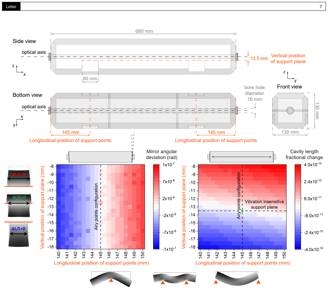
Airy points
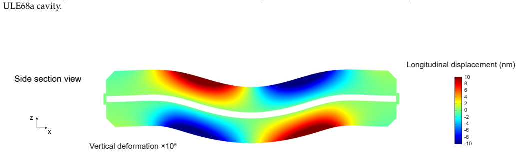
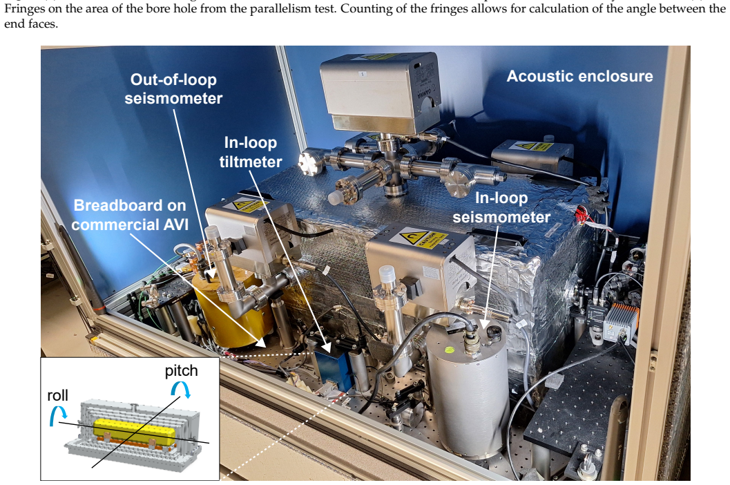
CAVITY DESIGN AND EXPERIMENTAL SET -UP A. Design to minimize sensitivity to accelerations To reduce sensitivity to accelerations, the geometry of the cavity is carefully optimized based on finite-element-method (FEM) simulations in the design phase, whilst also considering practi- cal limitations in the machining phase. As explained in the main text, the ...
-
[27]
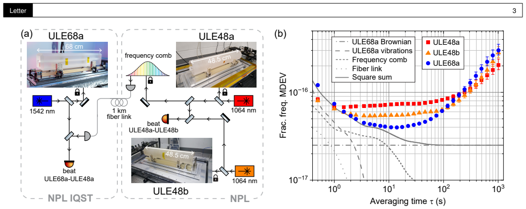
THREE-CORNERED HAT METHOD The three-cornered hat method is a well established technique for separating individual instability contributions from beat mea- surements of three independent oscillators [ 22]. For frequency oscillators a, b, and c with similar noise profiles, starting from the beats measured for the pairs ab, ac, and bc, we can derive the rela...
-
[28]
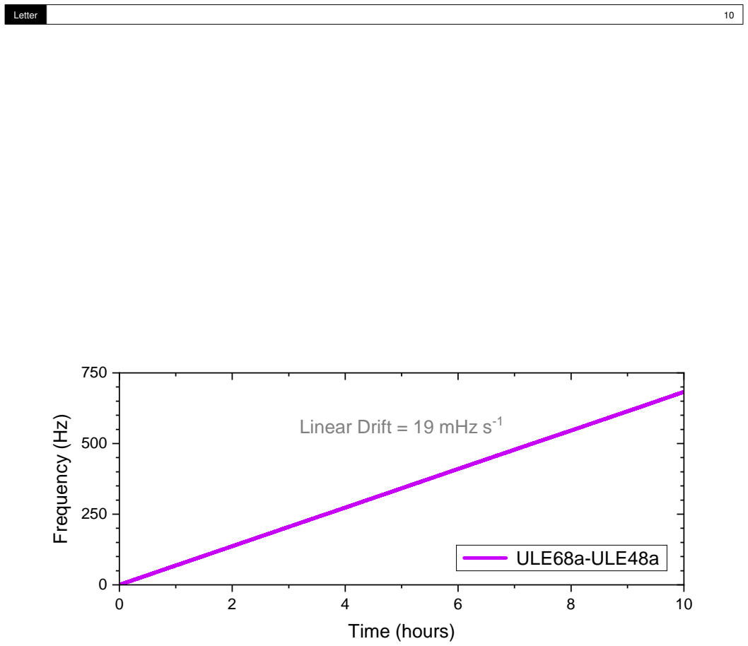
2 of the main text was taken over a continuous period of 10 hours
LINEAR DRIFT The three-cornered hat measurement presented in Fig. 2 of the main text was taken over a continuous period of 10 hours. The linear drift of ULE48a is hardware-removed at the mHz s−1 level, measured with an optical atomic clock. The hardware de-drift rate for ULE48a is set at the beginning of the measurement of the beat ULE68a-ULE48a. In this ...
discussion (0)
Sign in with ORCID, Apple, or X to comment. Anyone can read and Pith papers without signing in.