REVIEW 4 major objections 4 minor 19 references
High-accuracy ultrasonic positioning of calibration sources in the Jiangmen Underground Neutrino Observatory
T0 review · 4 major / 4 minor · reviewed 2026-08-01 · deepseek-v4-flash
Pith's one-line read An ultrasonic time-of-flight system can position calibration sources inside a large liquid-scintillator neutrino detector to within 1.23 cm on the central axis and 2.40 cm in an off-axis plane, according to this paper.
desk verdict Useful JUNO calibration engineering, but the headline 1.23 cm and 2.40 cm numbers are in-sample and simulation-only; the hardware work is solid, the validation is not yet. read the letter →
The pith
A machine-rendered reading of the paper's core claim, the machinery that carries it, and where it could break.
The reading
What carries the argument
The load-bearing object is the in-situ calibration of the 'effective receiver geometry'. Since the acrylic sphere deforms after filling and the surveyed receiver positions shift by 1–10 cm relative to the photomultiplier-tube reference frame, the paper treats the six receiver coordinates as free parameters in a global fit against time-of-flight measurements to 33 ACU positions that are taken as known truth. This calibrated geometry, combined with a custom laboratory-derived linear sound-speed-versus-temperature relation for the liquid scintillator (1469.69 − 3.916·T m/s over 18–22.5 °C) and a fixed-peak arrival-time algorithm with roughly 0.5 microsecond resolution, is what carries the centi
What would settle it
Deploy the CLS source at a set of points whose true positions are determined independently (e.g., by the calibrated cable-loop metrology or a CCD camera system), reconstruct the positions with the ultrasonic system, and compare the three-dimensional residuals across the full plane. If the RMS deviation exceeds the claimed 2.40 cm, or if the residual pattern correlates with the central-axis calibration positions, the off-axis extrapolation is not supported.
Extended reading notes
Core claim
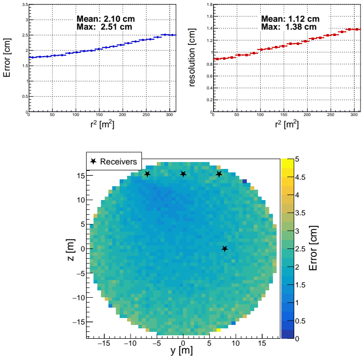
The central claim is that the limiting obstacles to acoustic positioning in a large liquid-scintillator detector are not fundamental. By measuring the temperature-dependent sound speed of the scintillator in the laboratory, reconstructing arrival times from a fixed peak in the received waveform, and re-fitting the six effective receiver coordinates in situ using 33 known central-axis emitter positions, the system removes the dominant systematic errors. After calibration, the mean three-dimensional positioning error along the central axis drops from 14.75 cm to 1.23 cm. A simulation of the off-axis CLS plane, smearing receiver coordinates by 0.8 cm, arrival times by 0.5 microseconds, and incl
Load-bearing premise
The 33 central-axis ACU deployments are treated as exactly known positions in the photomultiplier-tube reference frame when fitting the six receiver coordinates, and that fitted geometry is assumed to hold across the off-axis CLS plane with only an independent 0.8 cm Gaussian smearing to represent its uncertainty.
Editorial extensions
If this is right
- JUNO's CLS and ROV calibration campaigns can rely on USS-reported positions to build detector response maps over off-axis volumes.
- The online variant of the system gives operators real-time position feedback (about 30 s per point), sufficient to steer the source safely and to seed the offline reconstruction.
- The 2.40 cm RMSE in the CLS plane corresponds to a relative accuracy of about 0.14% of the acrylic radius, matching the order of magnitude of benchmarks from other large detectors.
- Receiver-geometry optimization or adding receivers would reduce the remaining directional weakness, particularly in the vertical direction.
- The sound-speed calibration procedure and the in-situ receiver-fitting procedure are transferable to other liquid-scintillator or water detectors with similar geometry.
Reading between the lines
- The 1.23 cm central-axis result is measured against the ACU's own mechanical reference, so it validates the full chain but cannot resolve a common-mode error shared by both the ACU reference and the USS reconstruction.
- The off-axis 2.40 cm figure rests on the assumption that receiver-coordinate errors remain Gaussian at 0.8 cm outside the calibrated central axis; a future independent off-axis truth reference (such as a CCD camera or cable metrology) could test this directly.
- The 5% adjacent-peak misidentification probability, if underestimated, could dominate the tails of the position-error distribution rather than the mean; waveform-level checks on noisy channels would settle it.
- The same trigger-aligned time-of-flight approach could be extended to sparse arrays with more than six receivers, where the vertical degeneracy noted by the authors would be further reduced.
Signed reviews
Editorial analysis
A structured set of objections, weighed in public.
Referee Report
Summary. The paper presents an ultrasonic positioning system (USS) for JUNO calibration sources. The system determines source coordinates by fitting time-of-flight measurements to a sound-speed model based on laboratory LS measurements and in-detector temperature profiles, with arrival times extracted by a fixed-peak method. An in-situ calibration of the six active receiver coordinates is performed using 33 central-axis ACU deployments, after which the central-axis reconstruction yields a mean 3D error of 1.23 cm (Fig. 10). For off-axis CLS operation, a detector-realistic simulation with timing jitter, sound-speed variation, and receiver smearing predicts an RMSE of 2.40 cm across the CLS plane (Fig. 15). The paper argues that these results demonstrate centimetre-level source positioning and support off-axis calibration in JUNO-like detectors.
Significance. If the claimed accuracy holds, the USS would enable off-axis calibration in JUNO without mechanical position control, which is an important capability for the experiment's physics program. The paper's strengths include the integration of a custom sound-speed measurement, careful waveform-based arrival-time extraction, and a realistic simulation chain with parameters tied to measured data. The in-situ calibration of receiver geometry under filled-detector conditions is a useful contribution, and the central-axis improvement from 14.75 cm to 1.23 cm clearly shows that the calibration corrects large survey/deformation offsets. However, the central-axis result is an in-sample residual of the same fit that determines the receiver coordinates, and the off-axis result rests on a simulation with no independent ground truth. These two limitations are load-bearing for the central claim and need to be addressed before the paper can support its conclusion.
major comments (4)
- [§4, Fig. 10] The 1.23 cm central-axis mean error is computed on the same 33 ACU deployments used to fit the six receiver coordinates. This is an in-sample residual of the calibration fit, not an out-of-sample accuracy measurement. Any systematic error in the ACU reference frame (cable zero offset, tilt, thermal expansion) is absorbed by the fitted receiver positions and does not appear in the residual. Please provide a leave-one-out or independent validation (e.g., a subset of ACU positions reserved from the calibration, or a comparison with the CLS anchor) to substantiate the absolute accuracy claim.
- [§6, Table 1] The off-axis 2.40 cm RMSE is entirely simulation-based. The 0.8 cm receiver smearing is taken from the statistical covariance of the central-axis calibration and is added as independent Gaussians. This models only random fitting uncertainty; a common-mode bias in the ACU reference or an off-axis drift of effective receiver positions would shift both the central-axis and off-axis results in the same direction and is not covered by the smearing. The CLS anchor visible in Fig. 11 is not used as an independent cross-check. Please include a measurement-based off-axis validation, or at least quantify the sensitivity to a global receiver-geometry bias (e.g., by offsetting all fitted R_i coherently) and to the ACU reference uncertainty.
- [§3.1, §6] The temperature field is assumed horizontally uniform, with variation only along z. The CLS plane extends to r = 17.7 m, so an unmeasured horizontal gradient of only ~0.5 °C would change the sound speed by ~2 m/s (using Vsound = 1469.69 − 3.916 T), producing path-length errors of order 1 cm—comparable to the claimed 2.40 cm RMSE. The simulation uses a single sound-speed value with ±0.9 m/s smearing (Table 1), which is not equivalent to a spatially varying field. Please justify the horizontal-uniformity assumption with data or include a horizontal gradient in the simulation to estimate its impact.
- [§6.1, Eq. (1)] The reconstruction treats all six receivers with equal weights and uses t0 as a free parameter per event. The calibration in §4 also fits receiver coordinates while assuming emitter positions are exact ground truth. It would be helpful to explicitly state whether the 0.8 cm receiver-parameter uncertainty is fully propagated into the central-axis residual (Fig. 10) or whether the residual is computed with receiver coordinates fixed at the fitted values. If the latter, the reported 1.23 cm does not include the calibration's own covariance contribution and is optimistic.
minor comments (4)
- [§2 / Fig. 3 caption] The text refers to a resonant frequency of 142 Hz for the piezoelectric element; this must be a typo (likely 142 kHz). Please correct.
- [§3.1, Eq. after Fig. 6] The fitting formula Vsound,LS = 1469.69 − 3.916×T is given without units for the coefficients and without an uncertainty on the slope. Adding the fit uncertainty and noting the valid temperature range (already stated) would help the reader propagate the sound-speed error.
- [§3.2, Fig. 9] Figure 9 shows the resolution for four methods with and without a 5% adjacent-peak contamination. It would be useful to state explicitly how the 5% fraction was obtained from manual counting and whether the same fraction is applied in the simulation consistently.
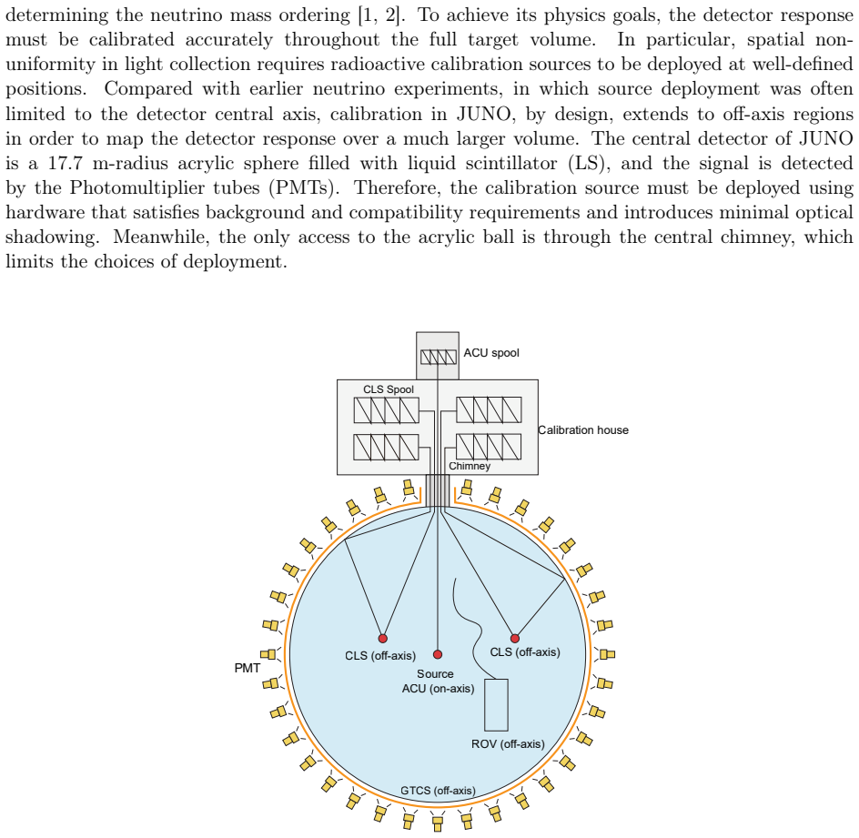
- [§5.2, Fig. 11] The CLS anchor is marked but never used as a positioning cross-check. Since it is a known reference point, a sentence explaining why it is not used (or using it) would strengthen the paper.
Circularity Check
Central-axis 1.23 cm is an in-sample residual of the receiver-geometry fit; off-axis 2.40 cm is a simulation seeded by that same fit's covariance, so the headline errors are not independent validations.
-
fitted input called prediction
[Section 4 (USS calibration) and Fig. 10; relatedly Section 6 / Table 1]
"The receiver coordinates are treated as free parameters, whereas the emitter positions are fixed at the pre-defined coordinates in the PMT reference frame. ... The overall mean positioning error is 1.23 cm. [Fig. 10 caption:] During the calibration process, a single emitter is positioned at 33 predefined positions along the central axis. The residuals are defined as the differences between the USS-reconstructed coordinates and the predefined positions."
The same 33 ACU emitter positions serve both as the fixed inputs of the calibration fit (receiver coordinates free) and as the 'truth' for the reported residual. Equation (1) reconstructs source positions using the fitted receiver coordinates R_i, so the 1.23 cm figure is a training-set residual quantifying how well the fitted geometry reproduces the calibration data, not an out-of-sample accuracy measurement. Systematic errors in the ACU reference (cable zero-point, coordinate-frame tilt, thermal expansion) are absorbed into the fitted receiver coordinates and cannot appear in this residual. The off-axis simulation then injects only the 0.8 cm random covariance from this same fit, so both headline numbers inherit the same common-mode blind spots.
full rationale
The paper's only measured accuracy number is computed on the same 33 central-axis deployments used to fit the six receiver coordinates. The calibration fixes the ACU emitter positions as ground truth and optimizes receiver coordinates to match those TOFs; the 1.23 cm mean error is then the reconstruction residual on those same fixed positions, so it is partially circular as an accuracy claim. The off-axis 2.40 cm result is a simulation, not a measurement, and its receiver-position smearing is derived from the covariance of that same central-axis fit; it therefore propagates the fitted random uncertainty but cannot cover a common-mode ACU or effective-geometry bias. The sound-speed and timing inputs are externally measured, and the off-axis simulation does include independent physical effects, so the circularity is partial rather than total. A held-out validation (e.g., the visible CLS anchor, an independent receiver survey, or a withheld subset of ACU deployments) would be needed to convert the in-sample residual into an independent accuracy statement. No load-bearing self-citation or imported uniqueness theorem is present.
Assumptions & free parameters
free parameters (5)
- sound_speed_intercept =
1469.69 m/s
- sound_speed_slope =
-3.916 m/(s·°C)
- receiver_coordinates_Ri =
not reported (18 DOF, six receivers)
- receiver_position_smearing =
0.8 cm (per-coordinate Gaussian σ)
- adjacent_peak_fraction =
5% (2.5% early + 2.5% late, ±7 µs)
assumptions (6)
- domain assumption Temperature field in the liquid scintillator is horizontally uniform and varies only along the z-axis.
- domain assumption Pressure and composition effects on the speed of sound are subdominant over the operating range.
- domain assumption The 33 ACU central-axis deployment positions are exact ground truth in the PMT reference frame.
- domain assumption The synthetic waveform simulation (parabolic rise, exponential decay, fourth-peak alignment) faithfully represents real USS waveforms.
- domain assumption The 0.82 cm statistical uncertainty from the Ceres fit fully characterizes receiver-position uncertainty (independent Gaussian smearing).
- standard math The TMinuit and Ceres minimizers converge to the global optimum of the nonlinear least-squares problem in Eq. (1).
Cite this review
Pith. "Pith review of High-accuracy ultrasonic positioning of calibration sources in the Jiangmen Underground Neutrino Observatory." pith.science (2026). https://pith.science/paper/NB5WSDNO
@misc{pith2026260720354,
  author       = {Pith},
  title        = {Pith review of: High-accuracy ultrasonic positioning of calibration sources in the Jiangmen Underground Neutrino Observatory},
  year         = {2026},
  howpublished = {\url{https://pith.science/paper/NB5WSDNO}},
  note         = {Machine review of arXiv:2607.20354}
}
read the original abstract
Precise source positioning is essential for detector calibration in large liquid scintillator detectors such as JUNO, particularly in regions where purely mechanical control is insufficient. An ultrasonic positioning system has been developed to reconstruct the three-dimensional coordinates of a calibration source without interfering with photon collection or contaminating the liquid scintillator. The method combines a sound-speed modeling based on dedicated laboratory measurements and in-detector temperature profiles, waveform-based arrival-time reconstruction, and an in-situ calibration of the effective receiver geometry using central-axis deployments. With six active receivers, central-axis positioning yields a mean error of 1.23 cm relative to the known deployment reference. For off-axis operation in the Cable Loop System calibration plane, a detector-realistic simulation that includes timing resolution, sound-speed variation, and receiver-coordinate smearing predicts a positioning uncertainty of 2.40 cm. These results demonstrate that ultrasonic positioning can provide centimetre-level source accuracy for large liquid scintillator detectors and can support off-axis calibration in JUNO-like experiments.
Figures


Figures from the paper (13 more)


Reference graph
Works this paper leans on
-
[1]
URLhttps://doi.org/10.1088/0954-3899/43/3/030401
JUNO collaboration, Neutrino physics with juno, Journal of Physics G: Nuclear and Particle Physics 43 (3) (2016) 030401.doi:10.1088/0954-3899/43/3/030401. URLhttps://doi.org/10.1088/0954-3899/43/3/030401
-
[2]
URLhttps://arxiv.org/abs/2511.14593
JUNO collaboration, First measurement of reactor neutrino oscillations at juno (2025).arXiv: 2511.14593. URLhttps://arxiv.org/abs/2511.14593
arXiv 2025
-
[3]
K. Feng, D. Li, Y. Shi, K. Qin, K. Luo, A novel remotely operated vehicle as the calibration system in juno, Journal of Instrumentation 13 (12) (2018) T12001.doi:10.1088/1748-0221/ 13/12/T12001. URLhttps://doi.org/10.1088/1748-0221/13/12/T12001
- [4]
-
[5]
J. Hui, R. Li, Y. Wu, T. Zhang, Z. Chen, A. Freegard, J. Huang, H. Lai, Y. Liao, J. Liu, Y. Meng, A. Takenaka, Z. Xiang, P. Zhang, Y. Zhang, The calibration house in juno, Journal of Instrumentation 20 (10) (2025) P10035.doi:10.1088/1748-0221/20/10/P10035. URLhttps://doi.org/10.1088/1748-0221/20/10/P10035
-
[6]
J. Hui, et al., The automatic calibration unit in JUNO, JINST 16 (08) (2021) T08008.arXiv: 2104.02579,doi:10.1088/1748-0221/16/08/T08008
arXiv 2021
-
[7]
arXiv:2011.06405,doi:10.1007/JHEP03(2021)004
JUNO collaboration, Calibration Strategy of the JUNO Experiment, JHEP 03 (2021) 004. arXiv:2011.06405,doi:10.1007/JHEP03(2021)004
arXiv 2021
-
[8]
Yang, Research on positioning algorithm of ccd positioning subsystem in juno calibration system, Master’s thesis, Dongguan University of Technology, Dongguan (2022)
T. Yang, Research on positioning algorithm of ccd positioning subsystem in juno calibration system, Master’s thesis, Dongguan University of Technology, Dongguan (2022)
2022
Show all 19 references
-
[9]
G. Zhu, W. Yang, D. Teng, Q. Wang, J. Hui, J. Lian, Experiments of ultrasonic positioning system with symmetrical array used in jiangmen underground neutrino observatory, Symmetry 16 (9) (2024).doi:10.3390/sym16091218. URLhttps://www.mdpi.com/2073-8994/16/9/1218
2024 doi
-
[10]
Zhu, J.-L
G.-L. Zhu, J.-L. Liu, Q. Wang, M.-J. Xiao, T. Zhang, Ultrasonic positioning system for the calibration of central detector, Nucl. Sci. Tech. 30 (1) (2019) 5.doi:10.1007/ s41365-018-0530-x
2019
-
[11]
Teng, J.-L
D. Teng, J.-L. Liu, G.-L. Zhu, Y. Meng, Y.-y. Zhang, T. Zhang, K. Luo, R. Li, J.- Q. Hui, Low-radioactivity ultrasonic hydrophone used in positioning system for jiangmen underground neutrino observatory, Nuclear Science and Techniques 33 (2022) 76.doi: 10.1007/s41365-022-01059-1
2022 doi
-
[12]
V. A. Del Grosso, New equation for the speed of sound in pure water, The Journal of the Acoustical Society of America 56 (4) (1974) 1084–1091.doi:10.1121/1.1903388. 18
1974 doi
-
[13]
James, M
F. James, M. Roos, Minuit: A system for function minimization and analysis of the parameter errors and correlations, Computer Physics Communications 10 (6) (1975) 343–367.doi:10. 1016/0010-4655(75)90039-9
1975
-
[14]
J. Liu, B. Cai, R. Carr, D. Dwyer, W. Gu, G. Li, X. Qian, R. McKeown, R. Tsang, W. Wang, F. Wu, C. Zhang, Automated calibration system for a high-precision measurement of neutrino mixingangleθ 13 withthedayabayantineutrinodetectors, NuclearInstrumentsandMethodsin Physics Resea...
2014 doi
-
[15]
Agarwal, K
S. Agarwal, K. Mierle, Others, Ceres solver,http://ceres-solver.org, accessed: 2026-04-07 (2023)
2026
-
[16]
Fang, The online event classification software in the juno experiment, Contribution to CHEP 2026, indico contribution page (2026)
W. Fang, The online event classification software in the juno experiment, Contribution to CHEP 2026, indico contribution page (2026). URLhttps://indico.cern.ch/event/1471803/contributions/6967321/
2026
-
[17]
URLhttps://www.sciencedirect.com/science/article/pii/S016890021301646X
Super-Kamiokande Collaboration, Calibration of the super-kamiokande detector, Nuclear Instruments and Methods in Physics Research Section A: Accelerators, Spectrometers, Detectors and Associated Equipment 737 (2014) 253–272.doi:https://doi.org/10.1016/ j.nima.2013.11.081. URLh...
2014
-
[18]
Berger, J
B. Berger, J. Busenitz, T. Classen, M. Decowski, D. Dwyer, G. Elor, A. Frank, S. Freedman, B. Fujikawa, M. Galloway, F. Gray, K. Heeger, L. Hsu, K. Ichimura, R. Kadel, G. Keefer, C. Lendvai, D. McKee, T. O’Donnell, J. Ricol, The kamland full-volume calibration system, Journal ...
2009 doi
-
[19]
Bayes, for the SNO+ Collaboration, Calibration hardware for sno+, Journal of Physics: Conference Series 1342 (1) (2020) 012108.doi:10.1088/1742-6596/1342/1/012108
R. Bayes, for the SNO+ Collaboration, Calibration hardware for sno+, Journal of Physics: Conference Series 1342 (1) (2020) 012108.doi:10.1088/1742-6596/1342/1/012108. URLhttps://doi.org/10.1088/1742-6596/1342/1/012108 19
2020 doi
Reviewed August 1, 2026 · model on record in the stance chip above.
Discussion (0). Continue with ORCID to comment.