REVIEW 4 major objections 4 minor 1 cited by
Non-dispersive graded impedance acoustic lenses
T0 review · 4 major / 4 minor · reviewed 2026-08-10 · deepseek-v4-flash
Pith's one-line read Grading an acoustic lens's impedance as 1/(x+a)^2 keeps every transmitted wave at the background phase velocity; in 2D the same holds with the radial index integral replacing x.
desk verdict The 2D non-dispersive impedance family and the generalized R/T formula are new and well derived, but the unanalyzed center singularity is the real weak spot, and the 1D profile overlaps with the conical horn solution. read the letter →
The pith
A machine-rendered reading of the paper's core claim, the machinery that carries it, and where it could break.
The reading
What carries the argument
The load-bearing object is the traveling-wave ansatz $p_\alpha=G(x,p_1(x\pm c_0t))$ (in 2D, $G(r,p_1)$) with $p_1$ an arbitrary solution of the impedance-matched equation. Substituting it into the graded wave equation and requiring the identity to hold for every $p_1$ separates the terms into three independent differential constraints (Eqs. (10a)-(10c)); these force $G$ to be linear in $p$, then fix the impedance to the quadratic-mean profile: $1/\alpha=(x+a_{1,nd})^2/a_{0,nd}$ in 1D, and $1/\alpha=(a_{1,nd}+N(r))^2/a_{0,nd}$ in 2D. A second mechanism carries the interface part: the generalized transmission and reflection coefficients (Eqs. (22)-(23)) obtained by matching pressure and velocity at a junction of two locally power-law-graded media show that reflection has a purely geometric part from impedance jumps and a slope-change part $g'$ that grows at low frequency, so a dispersion-free interior cannot be joined to a homogeneous background without paying an interface price.
What would settle it
Build a 1D waveguide whose density and bulk modulus follow $\rho_1/\rho_0=K_1/K_0=a_{0,nd}(x+a_{1,nd})^{-2}$ with the ends matched to the background, and send in a broadband pulse; the paper predicts the transmitted pulse arrives with every frequency component at speed $c_0$, shape preserved up to the envelope $(x+a_{1,nd})^{-1}$, and with low-frequency reflection governed by Eq. (22)-induced behavior $R\to-1$, $T\to 0$ as $\omega\to 0$. If a frequency-dependent phase shift (volume dispersion) or an extra cutoff appears where the profile is smooth, Eq. (16a) is refuted.
Extended reading notes
Core claim
The central claim is an exact family of impedance distributions that are dispersion-free by construction. Starting from the 1D wave equation under the grading condition $\rho_1/\rho_0=K_1/K_0=\alpha(x)$ (so the sound speed stays constant), the paper looks for traveling-wave solutions $p_\alpha=G(x,p_1(x\pm c_0t))$ whose shape in the wave argument is preserved; demanding the substitution identity hold for arbitrary $p_1$ forces $G(x,p)=g(x)p+h(x)$ and yields $\alpha_{nd}(x)=a_{0,nd}(x+a_{1,nd})^{-2}$ with $g\propto(x+a_{1,nd})^{-1}$. Media graded this way sustain $p_\alpha=g(x)p_1(x\pm c_0t)$ for any $p_1$, so all frequency components travel at $c_0$ and the only dispersion comes from slope discontinuities at interfaces, described by generalized Fresnel-type coefficients (Eqs. (22)-(23)) that reduce to the classical jump formulae when the profile slope is continuous. In 2D axisymmetry, the same construction with $G(r,p_1)$ gives $\alpha_{nd}(r)=a_{0,nd}(a_{1,nd}+N(r))^{-2}$, $N(r)=\int_0^r n(r')/r'\,dr'$, valid for any matched-lens solution $p_1$ and hence for any gradient-index profile. Applied to the Luneburg lens, the non-dispersive profile reaches useful transmission at a lower cutoff than exponential grading, keeps focal intensity closer to the matched-lens value, and shows significantly less phase distortion.
Load-bearing premise
The construction assumes a lens material can be made whose density and bulk modulus scale by the same factor $\alpha(x)$ while their ratio (the sound speed) stays fixed at the background value; if such independent $\rho$-$K$ grading is not achievable, the index profile changes and focusing is altered, and in 2D the impedance must in addition vanish at the lens center, a requirement the paper handles only by proposing an undemonstrated void or central sensor.
Editorial extensions
If this is right
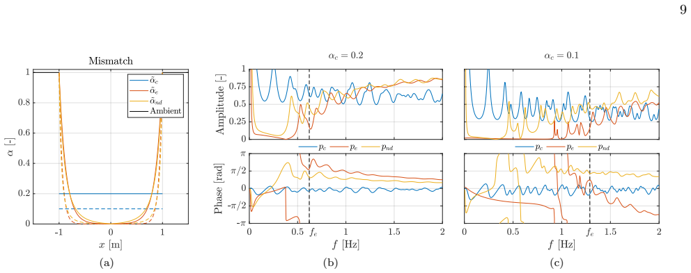
- Lens designers gain a free design axis: impedance can be reduced far below the background value (to about 4% at the center for $\alpha_c=0.2$) while the refractive index and imaging behavior are unchanged, relaxing fabrication demands for acoustic devices in air and water.
- A low-frequency gap is unavoidable for any non-constant impedance profile: total reflection as $\omega\to 0$ and inefficient energy transport near the cutoff are general features, not artifacts of the exponential profile.
- For the Luneburg lens, the non-dispersive profile outperforms exponential grading: a lower cutoff that barely shifts with the average mismatch, higher average focal pressure, and much less phase distortion, making it the preferred choice when strong mismatch is unavoidable.
- The grading strategy applies to other physical systems governed by the same wave structure, such as polarized electromagnetic waves and anti-plane elasticity, and in transformation acoustics can be applied in the virtual isotropic domain before mapping to anisotropic parameters.
- Because the method works in the full-wave regime, it also covers devices whose index profiles come from coordinate transformations or full-wave design, such as Maxwell's fisheye and optical black hole configurations.
Reading between the lines
- Inference beyond the paper: the interface dispersion the paper treats as unavoidable could be moved or weakened by inserting a short buffer region whose impedance connects the two branches with continuous slope; Eqs. (22)-(23) give an explicit quantitative prediction for the new reflection before any simulation is run.
- Inference beyond the paper: the 2D requirement $\alpha\to 0$ at the lens center suggests a concrete test—a Luneburg lens built with a central void of growing radius should show the same focal intensity above cutoff, with the void's scattering setting a shortest operating wavelength; the paper asserts sufficiency of a small void but does not quantify this trade-off.
- Inference beyond the paper: because the construction preserves the full matched solution up to the factor $g(r)$, the same impedance grading could be applied to any transformation-based device whose matched solution is known, not just lenses; a numerical demonstration on an anisotropic cloak would settle its practical reach.
Signed reviews
Editorial analysis
A structured set of objections, weighed in public.
Referee Report
Summary. The paper proposes impedance profiles for acoustic lenses that preserve the refractive index and the phase velocity, so that wave signals retain their shape while propagating through the lens bulk. In 1D it derives the inverse-square family α_nd(x)=a0(x+a1)^{-2} and a generalized reflection/transmission formula for interfaces with a slope discontinuity. In 2D axisymmetry it derives α_nd(r)=a0(a1+N(r))^{-2} with N'(r)=n(r)/r and applies the construction to a Luneburg lens, comparing constant, exponential, and non-dispersive mismatch profiles by COMSOL simulations.
Significance. The 1D construction is exact, self-contained, and valuable: it gives an impedance grading that supports undistorted traveling waves for arbitrary signals while keeping the phase velocity fixed. The generalized interface formula (22)-(23) is a useful extension of the standard jump-impedance result. The 2D derivation is algebraically sound in the general axisymmetric setting, and the manuscript makes its numerical codes publicly available, which aids reproducibility. However, the concrete Luneburg implementation contains inconsistencies in the definition of N_L(r), in Table II, and in the treatment of the singular lens center, so the 2D numerical demonstration does not yet substantiate the central claim. If these issues are corrected, the method offers a practical design degree of freedom for acoustic and other wave systems.
major comments (4)
- [III, Eq. (30)] The function N_L(r) in Eq. (30) is not an antiderivative of n_L(r)/r. For n_L(r)=sqrt(2-r^2/R^2), differentiating n_L+sqrt(2)*atanh(n_L/sqrt(2)) gives -(4-n_L^2)/(r n_L), not n_L/r; the correct antiderivative is n_L-sqrt(2)*atanh(n_L/sqrt(2)) plus a constant. Consequently, the profiles used in the COMSOL simulations of Figs. 4 and 5 are not the non-dispersive profiles of Eq. (28b), and the comparison in Sec. III does not test the claimed construction as written.
- [III, Eq. (31) and Table II] Table II is inconsistent with the boundary condition (31b). With n_L(R)=1, Eq. (30) gives N_L(R)=1+sqrt(2)*atanh(1/sqrt(2))≈2.2465, so α_nd(R)=a0,nd/(a1,nd+2.2465)^2. The listed values a0,nd=6.7e-3 and a1,nd=0.16 give α_nd(R)≈1.2e-3, not 1, and the listed coefficients do not satisfy (31a) and (31b) simultaneously under either sign convention for the atanh term. The coefficients, the defining formula, or the stated constraints need to be corrected and the simulations rerun.
- [III, Eqs. (28b)-(29)] The definition of N(r) in Eq. (28b) is not well defined for the Luneburg profile: since n_L(0)=sqrt(2)>0, the improper integral ∫_0^r n_L(r')/r' dr' diverges for every r>0, not only at r=0. A regularized antiderivative is needed, and the resulting profile satisfies α→0 at r=0, so the medium is singular at the lens center. The proposed central void/sensor remedy is not incorporated in the theory or in the simulations; replacing the singular point by a void changes the boundary condition and destroys the exact non-dispersive property. The manuscript should state the regularization, specify the numerical treatment at the center, and test convergence with the void radius.
- [II.C, Eq. (23) and Fig. 2] The explanation of the low-frequency gap is internally inconsistent. The text says that Eq. (23) shows total reflection as ω→0, but Eq. (23) is the coefficient for a single interface between two semi-infinite graded media, whereas Fig. 2 shows perfect transmission at zero frequency for the finite lens. The zero-frequency limit of a finite lens with matched outer boundaries is governed by the complete geometry and approaches unity, so the low-frequency gap cannot be attributed to Eq. (23). This paragraph should be revised.
minor comments (4)
- [II.C, Table I] The column header a1,ndR [−] is ambiguous; it should read a1,nd/R [−] or explicitly state that R=1 m is used.
- [IV, Data availability] The code repository URL contains a space ('Graded impedance'); it should be percent-encoded, for example as .../Graded%20impedance.
- [II.B, Eq. (23)] The sentence 'Nearby the interface, any impedance profile can be approximated...' should be more precise: the replacement g'_± = Z'_±/(2Z±) is exact only for profiles of the form (16a), and is an approximation otherwise.
- [II.C] The statement that the non-dispersive profile 'introduces dispersion only at the interfaces' is true for the bulk, but the full-device transmission remains frequency dependent because of the interface reflections; the wording should distinguish bulk dispersion from interface dispersion.
Circularity Check
No significant circularity: the impedance profiles are derived from the wave equation via a traveling-wave ansatz, and the COMSOL comparisons are independent checks, not fitted outputs.
full rationale
The central derivation is self-contained. In Sec. II A the paper substitutes the traveling-wave ansatz p_alpha = G(x, p1(x - c0 t)) into the 1D wave equation (2) and requires the resulting expression (9) to vanish for every p1, which gives the independent conditions (10a)-(10c). Solving the ODE system (13a)-(13c) then produces the non-dispersive impedance family alpha_nd(x) = a0,nd (x + a1,nd)^-2 in Eq. (16a). This is a constructive derivation, not an equation that has been fitted to the transmission data. The integration constants are fixed by the boundary condition alpha(R) = 1 and by equating the average impedance of the three profiles via (24) and (31a)-(31b); these constraints are design-normalization choices, not performance targets, so the subsequent transmission and phase comparisons in Figs. 2 and 4 are not forced by construction. The 2D axisymmetric result alpha_nd(r) = a0,nd (a1,nd + N(r))^-2 in Eq. (28b) is obtained by repeating the same substitution in polar coordinates with N(r) = integral_0^r n(r')/r' dr'; although the algebra is compressed in the text, it invokes no external fitted parameter or prior result. The generalized interface formulas (22)-(23) follow from the continuity conditions (21) and reduce to the classical homogeneous-medium result when g' = 0, which is a consistency check rather than a circular input. The self-citations [34], [35], and [40] are background references or a pointer to a follow-up application; none carries the load of the derivation or forbids alternative profiles. The singular limiting behavior alpha(r -> 0+) = 0 is flagged as an implementation issue with proposed void or sensor remedies, but it is a feasibility concern, not a circular step. Overall the paper's predictions are derived from the wave equation and checked by independent COMSOL simulations, so there is no identifiable circularity.
Assumptions & free parameters
free parameters (1)
- average impedance mismatch αc =
0.1 and 0.2
assumptions (3)
- domain assumption Density and bulk modulus of the lens can be graded independently while keeping ρ1/ρ0 = K1/K0 = α, so sound speed remains c0 everywhere.
- standard math In 2D the matched-lens pressure field p1 can be rescaled by a radial factor g(r) to produce a solution of the mismatched equation; the derivation requires G(r,p) to depend only on p and r, not on tangential derivatives.
- domain assumption The required α→0 at the lens center can be realized, for example by a small void or by placing a sensor or object at center.
Cite this review
Pith. "Pith review of Non-dispersive graded impedance acoustic lenses." pith.science (2026). https://pith.science/paper/2SHY76L4
@misc{pith2026250100821,
  author       = {Pith},
  title        = {Pith review of: Non-dispersive graded impedance acoustic lenses},
  year         = {2026},
  howpublished = {\url{https://pith.science/paper/2SHY76L4}},
  note         = {Machine review of arXiv:2501.00821}
}
read the original abstract
Lenses are typically based on refractive index profiles derived from the geometric approximation of high-frequency waves, yet the critical issue of impedance mismatch is often neglected. Mismatched devices suffer from unwanted reflections and dispersion, which can significantly degrade performance in practical applications. In this work, we propose impedance profiles for lenses to achieve efficient wave transmission while maintaining the desired refractive index and minimizing dispersion effects. A family of impedance profiles is derived from the acoustic wave equation such that the phase velocity is preserved. First, the 1D setting is considered to explain how dispersion occurs inside a lens and at its interfaces. Then, the method is applied to 2D axisymmetric configurations where the impedance mismatch is radially redistributed. These profiles are demonstrated in the acoustic setting of a Luneburg lens, but can be easily extended to more general scenarios such as imaging or cloaking in air and water, where matching the impedance of the background poses significant challenges.
Figures


Figures from the paper (2 more)

Forward citations
Cited by 1 Pith paper
-
Reduced-weight near-cloaks for underwater invisibility
Combining the eikonal impedance-mismatch cloak with a near-cloak (α=0.8, R~eq=0.25) cuts the cloak mass to 75% of a perfect cloak while the computed TSCS stays comparable to published underwater cloak values.
Reference graph
Works this paper leans on
-
[1]
We assume that the general solution pα has the form pα = G(r, p1), (27) where the function G(r, p) explicitly depends on r and not on the tangential coordinate to enforce axial sym- metry. Substituting pα into (26) and repeating the same calculations as before but in polar coordinates, we obtain G(r, p) = g(r) p + h(r) (28a) αnd(r) = a0,nd a1,nd + N (r) −...
-
[2]
Whewell, The Cambridge and Dublin Mathematical Journal, Vol
W. Whewell, The Cambridge and Dublin Mathematical Journal, Vol. 9 (E. Johnson, 1854)
-
[3]
R. K. Luneburg, Mathematical theory of optics (Univ of California Press, 1966). 10 (a) (b) (c) (d) (e) (f) FIG. 5: Pressure (a–c) and intensity (d–f) fields of the L¨ uneburg lens with αc = 0.1. The black contour outlines the lens, and the computational domain is enclosed by PMLs, which are not shown. For improved readability, the intensity color scale is...
work page 1966
-
[4]
J. C. Mi˜ nano, Perfect imaging in a homogeneous three- dimensional region, Optics express 14, 9627 (2006)
work page 2006
-
[5]
S.-C. S. Lin, T. J. Huang, J.-H. Sun, and T.-T. Wu, Gradient-index phononic crystals, Physical Review B 79, 094302 (2009)
work page 2009
-
[6]
E. E. Narimanov and A. V. Kildishev, Optical black hole: Broadband omnidirectional light absorber, Applied Physics Letters 95 (2009)
work page 2009
-
[7]
X. Su, A. N. Norris, C. W. Cushing, M. R. Haberman, and P. S. Wilson, Broadband focusing of underwater sound using a transparent pentamode lens, The Journal of the Acoustical Society of America 141, 4408 (2017)
work page 2017
-
[8]
M. Rahm, D. Schurig, D. A. Roberts, S. A. Cummer, D. R. Smith, and J. B. Pendry, Design of electromag- netic cloaks and concentrators using form-invariant coor- dinate transformations of maxwell’s equations, Photonics and Nanostructures-fundamentals and Applications 6, 87 (2008)
work page 2008
Show all 41 references
-
[9]
J. B. Pendry, Negative refraction makes a perfect lens, Physical review letters 85, 3966 (2000)
2000
-
[10]
S. A. Ramakrishna and J. Pendry, Spherical perfect lens: Solutions of maxwell’s equations for spherical geometry, Physical Review B 69, 115115 (2004)
2004
-
[11]
J. B. Pendry, D. Schurig, and D. R. Smith, Controlling electromagnetic fields, Science 312, 1780 (2006)
2006
-
[12]
Leonhardt, Optical conformal mapping, Science 312, 1777 (2006)
U. Leonhardt, Optical conformal mapping, Science 312, 1777 (2006)
2006
-
[13]
S. A. Cummer and D. Schurig, One path to acoustic cloaking, New Journal of Physics 9, 45 (2007)
2007
-
[14]
A. N. Norris, Acoustic cloaking theory, Proceedings of the Royal Society A 464, 2411 (2008)
2008
-
[15]
Laude, Phononic crystals: artificial crystals for sonic, acoustic, and elastic waves , Vol
V. Laude, Phononic crystals: artificial crystals for sonic, acoustic, and elastic waves , Vol. 26 (Walter de Gruyter GmbH & Co KG, 2015)
2015
-
[16]
Kadic, T
M. Kadic, T. B¨ uckmann, R. Schittny, P. Gumbsch, and M. Wegener, Pentamode metamaterials with indepen- dently tailored bulk modulus and mass density, Physical Review Applied 2, 054007 (2014)
2014
-
[17]
Y. Chen, M. Zheng, X. Liu, Y. Bi, Z. Sun, P. Xiang, J. Yang, and G. Hu, Broadband solid cloak for underwa- ter acoustics, Physical Review B 95, 180104 (2017). 11
2017
-
[18]
D. E. Quadrelli, M. A. Casieri, G. Cazzulani, S. La Riv- iera, and F. Braghin, Experimental validation of a broad- band pentamode elliptical-shaped cloak for underwater acoustics, Extreme Mechanics Letters , 101526 (2021)
2021
-
[19]
Li and J
Q. Li and J. S. Vipperman, Three-dimensional penta- mode acoustic metamaterials with hexagonal unit cells, The Journal of the Acoustical Society of America 145, 1372 (2019)
2019
-
[20]
Brambilla, S
G. Brambilla, S. Cominelli, M. Verbicaro, G. Cazzulani, and F. Braghin, High bulk modulus pentamodes: The three-dimensional metal water, Extreme Mechanics Let- ters , 102267 (2024)
2024
-
[21]
Y. Bi, H. Jia, Z. Sun, Y. Yang, H. Zhao, and J. Yang, Experimental demonstration of three-dimensional broad- band underwater acoustic carpet cloak, Applied Physics Letters 112, 223502 (2018)
2018
-
[22]
Allam, K
A. Allam, K. Sabra, and A. Erturk, 3d-printed gradient- index phononic crystal lens for underwater acoustic wave focusing, Physical Review Applied 13, 064064 (2020)
2020
-
[23]
S. Ramo, J. R. Whinnery, and T. Van Duzer, Fields and waves in communication electronics (John Wiley & Sons, 1994)
1994
-
[24]
A. G. Webster, Acoustical impedance and the theory of horns and of the phonograph, Proceedings of the National Academy of Sciences 5, 275 (1919)
1919
-
[25]
R. W. Klopfenstein, A transmission line taper of im- proved design, Proceedings of the IRE 44, 31 (1956)
1956
-
[26]
A. H. Benade and E. Jansson, On plane and spherical waves in horns with nonunif orm flare: I. theory of radi- ation, resonance frequencies, and mode conversion, Acta Acustica united with Acustica 31, 79 (1974)
1974
-
[27]
P. C. Pedersen, O. Tretiak, and P. He, Impedance- matching properties of an inhomogeneous matching layer with continuously changing acoustic impedance, The Journal of the Acoustical Society of America 72, 327 (1982)
1982
-
[28]
Li, D.-Q
Z. Li, D.-Q. Yang, S.-L. Liu, S.-Y. Yu, M.-H. Lu, J. Zhu, S.-T. Zhang, M.-W. Zhu, X.-S. Guo, H.-D. Wu, et al. , Broadband gradient impedance matching using an acous- tic metamaterial for ultrasonic transducers, Scientific re- ports 7, 42863 (2017)
2017
-
[29]
Hui and P
D. Hui and P. K. Dutta, A new concept of shock miti- gation by impedance-graded materials, Composites Part B: Engineering 42, 2181 (2011)
2011
-
[30]
Fleury and A
R. Fleury and A. Al` u, Metamaterial buffer for broadband non-resonant impedance matching of obliquely incident acoustic waves, The Journal of the Acoustical Society of America 136, 2935 (2014)
2014
-
[31]
J. Luo, Y. Yang, Z. Yao, W. Lu, B. Hou, Z. H. Hang, C. T. Chan, and Y. Lai, Ultratransparent media and transformation optics with shifted spatial dispersions, Physical Review Letters 117, 223901 (2016)
2016
-
[32]
Kossoff, The effects of backing and matching on the performance of piezoelectric ceramic transducers, IEEE Transactions on sonics and ultrasonics 13, 20 (1966)
G. Kossoff, The effects of backing and matching on the performance of piezoelectric ceramic transducers, IEEE Transactions on sonics and ultrasonics 13, 20 (1966)
1966
-
[33]
W. Cai, U. K. Chettiar, A. V. Kildishev, and V. M. Sha- laev, Optical cloaking with metamaterials, Nature pho- tonics 1, 224 (2007)
2007
-
[34]
B.-I. Popa, L. Zigoneanu, and S. A. Cummer, Exper- imental acoustic ground cloak in air, Phys. Rev. Lett. 106, 253901 (2011)
2011
-
[35]
Cominelli, D
S. Cominelli, D. E. Quadrelli, C. Sinigaglia, and F. Braghin, Design of arbitrarily shaped acoustic cloaks through partial differential equation-constrained opti- mization satisfying sonic-metamaterial design require- ments, Proceedings of the Royal Society A478, 20210750 (2022)
2022
-
[36]
Cominelli and F
S. Cominelli and F. Braghin, Optimal design of broad- band, low-directivity graded index acoustic lenses for un- derwater communication, The Journal of the Acoustical Society of America 156, 1952 (2024)
2024
-
[37]
Zigoneanu, B.-I
L. Zigoneanu, B.-I. Popa, and S. A. Cummer, Three- dimensional broadband omnidirectional acoustic ground cloak, Nature materials 13, 352 (2014)
2014
-
[38]
Dupont, S
G. Dupont, S. Guenneau, O. Kimmoun, B. Molin, and S. Enoch, Cloaking a vertical cylinder via homogenization in the mild-slope equation, Journal of Fluid Mechanics 796, R1 (2016)
2016
-
[39]
W. Kan, V. M. Garc ´ ıa-Chocano, F. Cervera, B. Liang, X.-y. Zou, L.-l. Yin, J. Cheng, and J. S´ anchez-Dehesa, Broadband acoustic cloaking within an arbitrary hard cavity, Physical Review Applied 3, 064019 (2015)
2015
-
[40]
Leonhardt, Perfect imaging without negative refrac- tion, New Journal of Physics 11, 093040 (2009)
U. Leonhardt, Perfect imaging without negative refrac- tion, New Journal of Physics 11, 093040 (2009)
2009
-
[41]
D. E. Quadrelli, S. Cominelli, G. Cazzulani, and F. Braghin, Reduced-weight near-cloaks for underwater invisibility, arXiv preprint arXiv:2506.07593 (2025)
2025 arXiv
Reviewed August 10, 2026 · model on record in the stance chip above.
Discussion (0). Continue with ORCID to comment.