REVIEW 3 major objections 4 minor 39 references
Chemical Reactions-Based Microfluidic Transmitter and Receiver for Molecular Communication
T0 review · 3 major / 4 minor · reviewed 2026-08-14 · deepseek-v4-flash
Pith's one-line read This paper designs and analyzes a microfluidic molecular communication transceiver whose three-reaction transmitter shapes rectangular triggers into programmable concentration pulses and whose receiver demodulates pulses back to…
desk verdict The transmitter half is solid and worth citing; the receiver's analytical demodulation claim is broken as written, though the COMSOL results suggest it is repairable. read the letter →
The pith
A machine-rendered reading of the paper's core claim, the machinery that carries it, and where it could break.
The reading
What carries the argument
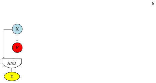
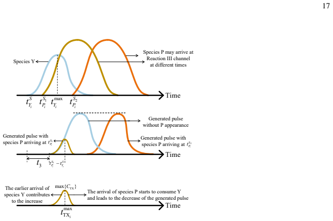
The load-bearing object is the microfluidic I1-FFL: a three-reaction chemical network whose timing is set by channel geometry instead of gene expression. Reaction I produces the pulse species $Y$ quickly, Reaction II produces the repressor species $P$ slowly through a deliberately longer serpentine channel, and Reaction III lets $P$ consume $Y$, so the $Y$ concentration rises and then falls. The same geometric principle appears in the receiver, where T junctions order Reaction IV before Reaction V so that the threshold reactant depletes the received signal before the amplifier converts the remainder into output $O$. The analytical machinery is the one-dimensional convection-diffusion-reaction equation with Taylor-Aris effective diffusion, whose rectangular-inlet solution and Gaussian-inlet approximations are the formulas used to size the channels and predict pulse shapes.
What would settle it
Inject a received Gaussian pulse whose peak is below the threshold reactant concentration $C_{ThL}^{VI}$ and measure the output $C_O(t)$: the intended thresholding operation predicts no rectangle, whereas the formula (40) as printed predicts a rectangle because $C_Y(\cdot) \geq 0$ always. A second sweep, varying the pulse peak around $C_{ThL}^{VI}$, would show whether the rectangle width tracks the time the signal stays above the threshold, as demodulation requires.
Extended reading notes
Core claim
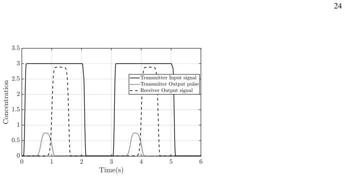
On the paper's own terms, the central claim is that the pulse-generating logic of the I1-FFL gene regulatory motif can be transplanted into a synthetic chemical reaction network running in a physical microfluidic device. The transmitter implements Reaction I ($X+S_y\to Y$), Reaction II ($X+S_p\to P$), and Reaction III ($Y+P\to Z$); because the Reaction II channel is a long serpentine, $P$ arrives at the Reaction III channel later than $Y$, so $Y$ first rises and is then consumed, producing a controlled pulse. The peak of that pulse is set by choosing the Reaction II channel length, and the paper gives a step-by-step optimization flow for that length. The receiver implements Reaction IV ($Y+\mathrm{ThL}\to\mathrm{Waste}$) as a threshold and Reaction V ($Y+\mathrm{Amp}\to Y+O$) as an amplifier, and the analysis approximates the demodulated output as a rectangle whose width is controlled by the threshold-reactant concentration and whose height is set by the amplifier concentration. The paper reports end-to-end finite-element simulations in which two rectangular input bits produce two transmitter pulses and two demodulated rectangular outputs at the receiver.
Load-bearing premise
Receiver demodulation stands on the assumption that the thresholding reaction removes every Y molecule below the ThL level and that any leftover Y then drives a fixed-amplitude amplifying reaction; the printed condition for output, $C_Y(\cdot) \geq 0$, is true for every incoming concentration, so the equations as written do not yet express the threshold the design story relies on.
Editorial extensions
If this is right
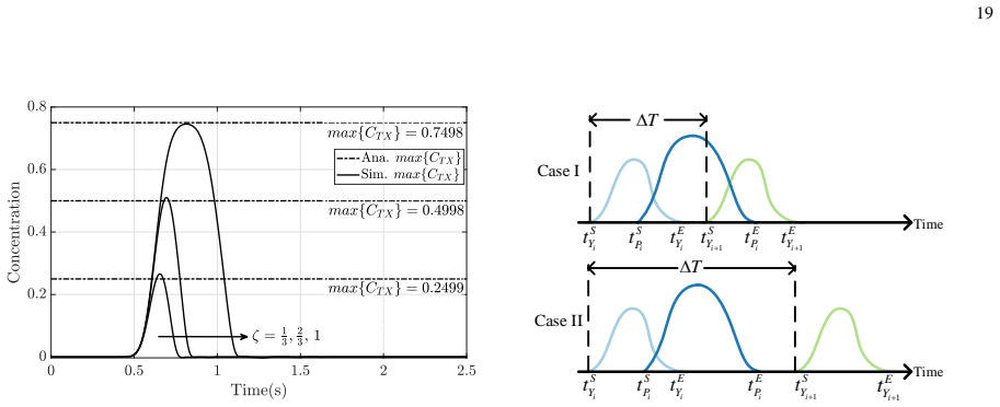
- A rectangular concentration input becomes a molecular pulse whose peak can be set in advance by choosing the number of delay lines in the Reaction II channel.
- Consecutive bits must be separated by at least $\Delta T \geq t^E_{Pi} - t^S_{Yi}$ to avoid distorting the second pulse; the paper derives this bound from its analytical channel responses.
- The receiver rectangle's width shrinks as the threshold reactant concentration $C_{ThL}^{VI}$ increases toward the received peak, and its height is set by the amplifier concentration $C_{Amp}^{VII}$.
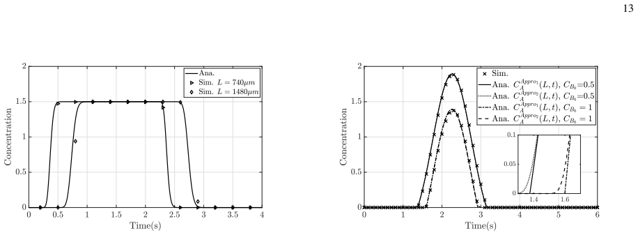
- When no reactant is continuously injected, the derived channel responses reduce to plain convection-diffusion solutions, so the same formulas cover propagation-only channels.
Reading between the lines
- The implicit generalization of the authors' approach is that other network motifs beyond the I1-FFL could be rebuilt as microfluidic chemical reaction networks whose timing is set by channel geometry; the paper does not propose this library, but its mechanism suggests it.
- A threshold condition written as 'residual $Y$ above the ThL level, not merely nonnegative' would make the demodulator's decision explicit and testable; the paper's formula (40) instead uses $C_Y(\cdot) \geq 0$, which holds for every input.
- A direct test of the receiver would be to inject a Gaussian pulse whose peak is below the threshold concentration: the intended thresholding logic predicts no output rectangle, while the printed formula predicts a rectangle.
- The constant $C_O = \tfrac{1}{3}C_{Amp}^{VII}$ assumes perfect one-to-one stoichiometry in the amplifying reaction; measuring the output for several amplifier concentrations would turn that assumption into a calibration curve and reveal any yield losses.
Signed reviews
Editorial analysis
A structured set of objections, weighed in public.
Referee Report
Summary. The manuscript proposes a microfluidic molecular communication transmitter and receiver that realize pulse generation and demodulation in the molecular domain. The transmitter uses three mass-action reactions inspired by the incoherent feed-forward loop, with microfluidic Y junctions, serpentine delays, and reaction channels to produce a predefined pulse from a rectangular input. The receiver uses a thresholding reaction with ThL and an amplifying reaction with Amp to convert a received Gaussian-like pulse into a rectangular output. The paper derives one-dimensional convection–diffusion–reaction channel responses for rectangular and Gaussian inlets (Theorems 1 and 2), a channel-length optimization flow for the transmitter, a minimum time-gap constraint between consecutive inputs, and COMSOL simulations that validate the transmitter pulse shapes, the receiver output, and a combined end-to-end implementation.
Significance. If the analytical derivations were corrected, the paper would be a useful design contribution: it gives concrete microfluidic layouts for chemical-reaction-based modulation and demodulation, derives rather than fits the channel responses, provides a reproducible design optimization, and validates the concepts in COMSOL. The transmitter analysis and its COMSOL comparisons are largely coherent, and the end-to-end demonstration is a nice integration. However, the receiver analysis contains two compounding errors: Theorem 2's premise and boundary condition are internally inconsistent, and Eq. (40)'s demodulation condition is trivially true, so the theoretical receiver response as written does not support the demodulation claim. The COMSOL results in Figs. 14–15 indicate that the intended threshold behavior is attainable, so these are repairable issues rather than a fundamental invalidation.
major comments (3)
- [Sec. III (Theorem 2) and Appendix B] The statement of Theorem 2 assumes CB0 > max{CA(0,t)}, but t1 and t2 in (20)–(21) are defined as the solutions to CA(0,t) = CB0, which do not exist under that inequality; the square-root arguments become negative. The residual formula (16) is nonnegative only when CB0 < max{CA(0,t)}, and the receiver application in (39) requires the same inequality. In addition, the boundary condition (56) sets CA(0,t) = CB0 on [t1,t2], which is not the residual CA(0,t) − CB0 used in (57) and (60). Thus the proof and the statement of Theorem 2 are internally inconsistent, and the receiver residual profile in (39) is not supported as written. The theorem premise and Eq. (56) should be corrected, for example to CB0 < max{CA(0,t)} and to the residual boundary condition used in (60).
- [Sec. V-A3, Eq. (40)] The demodulation condition CY(...) ≥ 0 is satisfied by every nonnegative concentration, so Eq. (40) as written predicts a constant output CO(t) = (1/3) C_Amp^VII whenever the time-shifted concentration is defined, i.e., it encodes no threshold transition and no demodulation. The paper's own description of Reaction IV requires a strict comparison, such as CY > 0 or CY above a tolerance, before Reaction V produces O, and the derivation should state how this threshold condition is obtained from the residual profile in Theorem 2. This is a load-bearing error because the receiver's rectangular-output claim rests on Eq. (40).
- [Sec. III, Theorem 1] In the statement of Theorem 1, h(x,t) is defined with the prefactor CA0, whereas the boundary condition used in the proof, Eq. (51), is Cs(0,t) = C0 with C0 = min{CA0,CB0}. Since the total concentration Cs = CA + CAB inherits its inlet level from CA(0,t) = C0, h should carry C0 as g does. With CA0 ≠ CB0, Eq. (14) is not the solution of the stated problem, and the transmitter formulas (25)–(28) that rely on (14) are affected. Please correct the prefactor and verify the numerical results for unequal CA0 and CB0.
minor comments (4)
- [Fig. 4 caption] The caption lists 'CA0 = CB0 = 1.5 mol/m3, CA0 = 3 mol/m3', which is ambiguous or contradictory; please restate the parameter values clearly.
- [Sec. IV-A1] The concentration of the reactant Sp at Inlet IV is written as CVI_Sp0, but the inlet is labeled IV; use CIV_Sp0 for consistency.
- [Sec. V-A4] The discussion of Fig. 13 attributes the delay mismatch to the T-junction approximation but does not quantify the discrepancy or check whether an adjusted effective time shift restores agreement; a sentence quantifying the error would strengthen the validation.
- [Abstract] The claim that the system 'overcomes' the slow-speed, unreliability, and non-scalability of biological processes is stronger than what COMSOL simulations can establish; consider wording such as 'addresses in simulation'.
Circularity Check
No circular derivation: analytical transmitter and receiver models are derived from stated reaction kinetics and validated against COMSOL; the receiver's internal inconsistencies are correctness defects, not circularity.
full rationale
The paper's central derivations are self-contained and externally benchmarked. The transmitter pulse response in Sec. IV is obtained by applying the derived convection-diffusion-reaction solution of Theorem 1 to reactions (1)-(3), and the L2 optimization flow uses the analytically derived CY and CP expressions rather than fitting any parameter to the COMSOL output. The receiver analysis in Sec. V-A similarly uses the stated Gaussian-input approximation (Theorem 2) with explicit substitutions, and Eq. (40) is a stoichiometric model of the amplifying reaction; the plotted comparisons do not tune parameters to force agreement. The only self-citation, [19], is motivational prior work for the transmitter concept and is independently re-derived with new analysis and COMSOL validation in this paper, so it is not load-bearing. There are genuine logical flaws in the receiver model as written: Theorem 2 states the premise CB0 > max{CA(0,t)} while defining t1 and t2 by solving CA(0,t)=CB0, which is inconsistent, and Eq. (40)'s condition CY(...) >= 0 is always true for a concentration, so the formula as written predicts constant output rather than threshold demodulation. These are correctness and consistency defects, not circular reductions: no target quantity is defined in terms of itself, no fitted parameter is renamed as a prediction, and no load-bearing claim rests on an unverified self-citation. Hence the circularity score is 0.
Assumptions & free parameters
free parameters (4)
- delta (numerical tolerance in L2 optimization) =
0.13 (Table II)
- epsilon (P concentration threshold in L2 optimization) =
1e-1, 3e-2, 1e-3 for 0, 1, and 2 delay lines (Table II)
- tau (time-gap threshold) =
1e-3
- modified max{CY} and t_max_Y =
0.7498 and 0.55 s (raw values 0.75 and 0.9511 s)
assumptions (7)
- domain assumption Flow is laminar Poiseuille flow and concentration obeys the 1D Taylor-Aris convection-diffusion equation (9) with effective diffusion coefficient Deff.
- domain assumption All chemical reactions are unbalanced, with forward rate much greater than reverse, and effectively go to completion in each reaction channel.
- ad hoc to paper Y-junction and T-junction outlets are time-shifted, diluted copies of inlet concentrations, with no diffusion or mixing dynamics (Eqs. 24, 37-38).
- domain assumption A serpentine channel can be modeled as a straight channel of equivalent length L2 = L21+L22+L23+4Hs+3Ls.
- domain assumption The received pulse at the receiver inlet follows a Gaussian concentration profile (36) with user-chosen mu and sigma^2.
- ad hoc to paper Reaction V output O depends only on presence or absence of Y, not on Y concentration, and equals 1/3 C_Amp when Y is present (Eq. 40).
- domain assumption The residual Y after Reaction IV is the positive part of the Gaussian minus the ThL concentration (Theorem 2).
invented entities (5)
-
Species Y (pulse-carrying molecule)
-
Species P (delayed repressor analog)
-
ThL (threshold reactant)
-
Amp (amplifier substrate)
-
Species O (demodulated output molecule)
Cite this review
Pith. "Pith review of Chemical Reactions-Based Microfluidic Transmitter and Receiver for Molecular Communication." pith.science (2026). https://pith.science/paper/3BUBAS2S
@misc{pith2026190803441,
  author       = {Pith},
  title        = {Pith review of: Chemical Reactions-Based Microfluidic Transmitter and Receiver for Molecular Communication},
  year         = {2026},
  howpublished = {\url{https://pith.science/paper/3BUBAS2S}},
  note         = {Machine review of arXiv:1908.03441}
}
read the original abstract
The design of communication systems capable of processing and exchanging information through molecules and chemical processes is a rapidly growing interdisciplinary field, which holds the promise to revolutionize how we realize computing and communication devices. While molecular communication (MC) theory has had major developments in recent years, more practical aspects in designing components capable of MC functionalities remain less explored. Motivated by this, we design a microfluidic MC system with a microfluidic MC transmitter and a microfluidic MC receiver based on chemical reactions. Considering existing MC literature on information transmission via molecular pulse modulation, the proposed microfluidic MC transmitter is capable of generating continuously predefined pulse-shaped molecular concentrations upon rectangular triggering signals using chemical reactions inspired by how cells generate pulse-shaped molecular signals in biology. We further design a microfluidic MC receiver capable of demodulating a received signal to a rectangular output signal using a thresholding reaction and an amplifying reaction. Our chemical reactions-based microfluidic molecular communication system is reproducible and well-designed, and more importantly, it overcomes the slow-speed, unreliability, and non-scalability of biological processes in cells. To reveal design insights, we also derive the theoretical signal responses for our designed microfluidic transmitter and receiver, which further facilitate the transmitter design optimization. Our theoretical results are validated via simulations performed through the COMSOL Multiphysics finite element solver. We demonstrate the predefined nature of the generated pulse and the demodulated rectangular signal together with their dependence on design parameters.
Figures


Figures from the paper (10 more)




Reference graph
Works this paper leans on
-
[1]
Nanonetworks: A new communication paradigm at molecular level,
I. F. Akyildiz, F. Brunetti, and C. Blazquez, “Nanonetworks: A new communication paradigm at molecular level,” Comput. Netw., vol. 52, no. 12, pp. 2260–2279, August 2008
work page 2008
-
[2]
The internet of bio-nano things,
I. F. Akyildiz, M. Pierobon, S. Balasubramaniam, and Y . Koucheryavy, “The internet of bio-nano things,” IEEE Commun. Mag., vol. 53, no. 3, pp. 32–40, March 2015
work page 2015
-
[3]
A comprehensive survey of recent advancements in molecular communication,
N. Farsad, H. B. Yilmaz, A. Eckford, C.-B. Chae, and W. Guo, “A comprehensive survey of recent advancements in molecular communication,” IEEE Commun. Surveys Tuts. , vol. 18, no. 3, pp. 1887–1919, Third Quarter 2016
work page 1919
-
[4]
H. C. Berg, Random walks in biology . Princeton, NJ, USA: Princeton Univ. Press, 1993
work page 1993
-
[5]
Bruus, Theoretical microfluidics
H. Bruus, Theoretical microfluidics. London, UK: Oxford Univ. Press, 2008
work page 2008
-
[6]
Improving receiver performance of diffusive molecular communication with enzymes,
A. Noel, K. C. Cheung, and R. Schober, “Improving receiver performance of diffusive molecular communication with enzymes,” IEEE Trans. Nanobiosci. , vol. 13, no. 1, pp. 31–43, March 2014
work page 2014
-
[7]
3d stochastic geometry model for large-scale molecular communication systems,
Y . Deng, A. Noel, W. Guo, A. Nallanathan, and M. Elkashlan, “3d stochastic geometry model for large-scale molecular communication systems,” in Proc. IEEE GLOBECOM , Dec 2016, pp. 1–6
work page 2016
-
[8]
B. Alberts, D. Bray, K. Hopkin, A. D. Johnson, J. Lewis, M. Raff, K. Roberts, and P. Walter, Essential cell biology. New York, NY , USA: Garland Science, 2013
work page 2013
Show all 39 references
-
[9]
Molecular communication with a reversible adsorption receiver,
Y . Deng, A. Noel, M. Elkashlan, A. Nallanathan, and K. C. Cheung, “Molecular communication with a reversible adsorption receiver,” in Proc. IEEE ICC , May 2016, pp. 1–7
2016
-
[10]
Capacity of a diffusion-based molecular communication system with channel memory and molecular noise,
M. Pierobon and I. F. Akyildiz, “Capacity of a diffusion-based molecular communication system with channel memory and molecular noise,” IEEE Trans. Inf. Theory , vol. 59, no. 2, pp. 942–954, Feb 2013
2013
-
[11]
On the capacity of diffusion-based molecular timing channels,
N. Farsad, Y . Murin, A. Eckford, and A. Goldsmith, “On the capacity of diffusion-based molecular timing channels,” in Proc. IEEE ISIT , July 2016, pp. 1023–1027. 30
2016
-
[12]
Interference mitigation in large-scale multiuser molecular communication,
M. B. Dissanayake, Y . Deng, A. Nallanathan, M. Elkashlan, and U. Mitra, “Interference mitigation in large-scale multiuser molecular communication,” IEEE Trans. Commun. , pp. 1–1, 2019
2019
-
[13]
Tabletop molecular communication: Text messages through chemical signals,
N. Farsad, W. Guo, and A. W. Eckford, “Tabletop molecular communication: Text messages through chemical signals,” PLoS One, vol. 8, no. 12, p. e82935, December 2013
2013
-
[14]
Molecular mimo: From theory to prototype,
B. Koo, C. Lee, H. B. Yilmaz, N. Farsad, A. Eckford, and C. Chae, “Molecular mimo: From theory to prototype,” IEEE J. Sel. Areas Commun. , vol. 34, no. 3, pp. 600–614, March 2016
2016
-
[15]
A chemical alphabet for macromolecular communications,
S. Giannoukos, D. T. McGuiness, A. Marshall, J. Smith, and S. Taylor, “A chemical alphabet for macromolecular communications,” Anal Chem, vol. 90, no. 12, pp. 7739–7746, May 2018
2018
-
[16]
Communications and switching in microfluidic systems: Pure hydrodynamic control for networking labs-on-a-chip,
E. De Leo, L. Donvito, L. Galluccio, A. Lombardo, G. Morabito, and L. M. Zanoli, “Communications and switching in microfluidic systems: Pure hydrodynamic control for networking labs-on-a-chip,” IEEE Trans. Commun. , vol. 61, no. 11, pp. 4663–4677, November 2013
2013
-
[17]
Time-elapse communication: Bacterial communication on a microfluidic chip,
B. Krishnaswamy, C. M. Austin, J. P. Bardill, D. Russakow, G. L. Holst, B. K. Hammer, C. R. Forest, and R. Sivakumar, “Time-elapse communication: Bacterial communication on a microfluidic chip,” IEEE Trans. Commun. , vol. 61, no. 12, pp. 5139–5151, December 2013
2013
-
[18]
Parity-check coding based on genetic circuits for engineered molecular communication between biological cells,
A. Marcone, M. Pierobon, and M. Magarini, “Parity-check coding based on genetic circuits for engineered molecular communication between biological cells,” IEEE Trans. Commun. , vol. 66, no. 12, pp. 6221–6236, December 2018
2018
-
[19]
A microfluidic feed forward loop pulse generator for molecular communica- tion,
Y . Deng, M. Pierobon, and A. Nallanathan, “A microfluidic feed forward loop pulse generator for molecular communica- tion,” in Proc. IEEE GLOBECOM , Dec 2017, pp. 1–7
2017
-
[20]
Genetic circuit building blocks for cellular computation, communications, and signal processing,
R. Weiss, S. Basu, S. Hooshangi, A. Kalmbach, D. Karig, R. Mehreja, and I. Netravali, “Genetic circuit building blocks for cellular computation, communications, and signal processing,” Nat. Comput., vol. 2, no. 1, pp. 47–84, Mar. 2003
2003
-
[21]
Programmability of chemical reaction networks,
M. Cook, D. Soloveichik, E. Winfree, and J. Bruck, “Programmability of chemical reaction networks,” in Algorithmic Bioprocesses. Springer, 2009, pp. 543–584
2009
-
[22]
Modulation in molecular communications: A look on methodologies,
E. B. Pehlivanoglu, B. D. Unluturk, and O. B. Akan, “Modulation in molecular communications: A look on methodologies,” in Modeling, Methodologies and Tools for Molecular and Nano-scale Communications . Springer International Publishing, 2017, pp. 79–97
2017
-
[23]
Analyzing large-scale multiuser molecular communication via 3-d stochastic geometry,
Y . Deng, A. Noel, W. Guo, A. Nallanathan, and M. Elkashlan, “Analyzing large-scale multiuser molecular communication via 3-d stochastic geometry,” IEEE Trans. Mol. Biol. Multi-Scale Commun. , vol. 3, no. 2, pp. 118–133, June 2017
2017
-
[24]
Modelling and analysis of gene regulatory networks,
G. Karlebach and R. Shamir, “Modelling and analysis of gene regulatory networks,” Nat. Rev. Mol. Cell Biol. , vol. 9, no. 10, pp. 770–780, October 2008
2008
-
[25]
Network motifs: simple building blocks of complex networks,
R. Milo, S. Shen-Orr, S. Itzkovitz, N. Kashtan, D. Chklovskii, and U. Alon, “Network motifs: simple building blocks of complex networks,” Science, vol. 298, no. 5594, pp. 824–827, October 2002
2002
-
[26]
Network motifs: theory and experimental approaches,
U. Alon, “Network motifs: theory and experimental approaches,” Nat. Rev. Genet., vol. 8, no. 6, pp. 450–461, June 2007
2007
-
[27]
Uri, An introduction to systems biology: design principles of biological circuits
A. Uri, An introduction to systems biology: design principles of biological circuits . London, UK: Chapman & Hall, 2006
2006
-
[28]
The incoherent feed-forward loop accelerates the response-time of the gal system of escherichia coli,
S. Mangan, S. Itzkovitz, A. Zaslaver, and U. Alon, “The incoherent feed-forward loop accelerates the response-time of the gal system of escherichia coli,” J Mol Biol , vol. 356, no. 5, pp. 1073–1081, March 2006
2006
-
[29]
A survey of enabling technologies in synthetic biology,
L. J. Kahl and D. Endy, “A survey of enabling technologies in synthetic biology,” Journal of Biol. Eng. , vol. 7, no. 1, p. 13, May 2013
2013
-
[30]
Modular and robust computation with deterministic chemical reaction networks,
T. H. Klinge, “Modular and robust computation with deterministic chemical reaction networks,” Ph.D. dissertation, 2016
2016
-
[31]
The origins and the future of microfluidics,
G. M. Whitesides, “The origins and the future of microfluidics,” Nature, vol. 442, no. 7101, pp. 368–373, July 2006
2006
-
[32]
X. J. Li and Y . Zhou, Microfluidic devices for biomedical applications . Sawston, UK: Woodhead, 2013
2013
-
[33]
Inertial microfluidics,
D. Di Carlo, “Inertial microfluidics,” Lab. Chip, vol. 9, no. 21, pp. 3038–3046, September 2009
2009
-
[34]
Stocker, Introduction to climate modelling
T. Stocker, Introduction to climate modelling . Berlin, Germany: Springer, 2011
2011
-
[35]
Modeling duct flow for molecular communication,
W. Wicke, T. Schwering, A. Ahmadzadeh, V . Jamali, A. Noel, and R. Schober, “Modeling duct flow for molecular communication,” in Proc. IEEE GLOBECOM , Dec 2018, pp. 206–212
2018
-
[36]
End-to-end propagation noise and memory analysis for molecular communication over microfluidic channels,
A. O. Bicen and I. F. Akyildiz, “End-to-end propagation noise and memory analysis for molecular communication over microfluidic channels,” IEEE Trans. Commun. , vol. 62, no. 7, pp. 2432–2443, July 2014
2014
-
[37]
Modeling and simulation of molecular communication systems with a reversible adsorption receiver,
Y . Deng, A. Noel, M. Elkashlan, A. Nallanathan, and K. C. Cheung, “Modeling and simulation of molecular communication systems with a reversible adsorption receiver,” IEEE Trans. Mol. Biol. Multi-Scale Commun. , vol. 1, no. 4, pp. 347–362, December 2015
2015
-
[38]
Hundsdorfer and J
W. Hundsdorfer and J. G. Verwer, Numerical solution of time-dependent advection-diffusion-reaction equations . New York, NY , USA: Springer, 2013
2013
-
[39]
The non-absolute convergence of gil-pelaez’inversion integral,
J. Wendel et al., “The non-absolute convergence of gil-pelaez’inversion integral,” The Annals of Mathematical Statistics , vol. 32, no. 1, pp. 338–339, 1961
1961
Reviewed August 14, 2026 · model on record in the stance chip above.
Discussion (0). Continue with ORCID to comment.