REVIEW 3 major objections 5 minor 33 references
Flow topology during multiplexed particle manipulation using a Stokes Trap
T0 review · 3 major / 5 minor · reviewed 2026-08-14 · deepseek-v4-flash
Pith's one-line read Optimal control of two particles in a Stokes trap does not use two stagnation points; it uses none first and then one, translated and rotated.
desk verdict A useful first look at flow topology in two-particle Stokes trap manipulation: the MPC-solution uses zero then one stagnation point, but the topology is inferred from the same model that drives the controller, so the experimental claim is conditional. read the letter →
The pith
A machine-rendered reading of the paper's core claim, the machinery that carries it, and where it could break.
The reading
What carries the argument
The load-bearing object is the two-dimensional Hele-Shaw point-source flow model, $$u(x)=\frac{1}{\pi H}\sum_{i=1}^{6}\frac{(x-R_i)q_i}{\|x-R_i\|^2},$$ which treats the six channel openings as point sources and sinks, so the same six flow rates $q_i$ generate both the predicted particle motion and the streamlines used to count stagnation points. The model-predictive controller (a scheme that repeatedly re-optimizes a plan over a future horizon) minimizes $$J=\sum_{k=0}^{K-1}\left(\|X_k-X_F\|^2+\$\beta$\|q_k\|^2\right)+\gamma\|X_K-X_F\|^2,$$ so the scalar weights $\beta$ (flow-rate penalty) and $\gamma$ (endpoint penalty) set the speed-versus-cost trade-off. The mechanism that carries the argument is the optimizer's freedom in choosing flow topology: it first selects a nearly uniform flow with no stagnation point, then a one-stagnation-point extensional flow, and by changing the $q_i$ it can translate that stagnation point and rotate its principal axes of compression and extension.
What would settle it
Measure the actual velocity field inside the cross-slot with particle tracking velocimetry while the controller performs a two-particle approach and count stagnation points in the measured vectors. If the real flow shows two stagnation points near the particles at any stage, or no stagnation point when the model predicts one, then the two-stage zero/one topology claim does not describe the physical flow.
Extended reading notes
Core claim
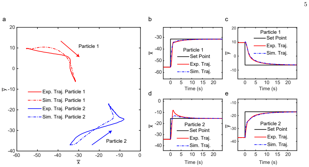
A six-channel cross-slot device can produce flows with zero, one, or two stagnation points depending on the flow rates, and particle tracking velocimetry confirmed that all three are experimentally realizable. The paper compares experimental particle trajectories with trajectories predicted by the point-source Hele-Shaw model that the model-predictive controller uses, and after accounting for initial transients the trajectories agree. Streamlines drawn from the model's flow rates then show that, during every optimal two-particle maneuver, the controller first moves both particles in a nearly uniform unidirectional flow with no stagnation point, then creates a single stagnation point between the particles and translates and rotates its extensional and compressional axes so the particles settle exponentially to their targets. The paper interprets this as a general two-stage strategy and argues that the simpler topology is preferable because relocation is faster and requires smaller flow rates than a scheme with one stagnation point per particle.
Load-bearing premise
The argument assumes the simplified fluid model used to draw the streamlines is accurate enough near the particles, because the flow topology is inferred from simulated flow rates rather than measured directly.
Editorial extensions
If this is right
- Two-particle manipulation can be scheduled as a two-stage flow pattern: uniform transport first, then one translating, rotating stagnation point for the final approach.
- Close-approach experiments such as collision, adhesion, or vesicle deformation can expect the particles to experience a planar extensional flow in the final stage, not a two-point trap flow.
- The measured weight maps give predictable performance trends: a larger flow-rate penalty increases the time to reach a target roughly linearly for smooth trajectories, while a larger endpoint penalty first speeds arrival and then saturates.
- The optimizer's one-stagnation-point choice means the practical control handle in a six-channel device is the position and rotation of a single strain axis, not the positions of two independent stagnation points.
Reading between the lines
- The paper does not test traps with more than two particles; a plausible extension is that the optimal topology remains a small number of shared stagnation structures with translating and rotating axes rather than one stagnation point per particle.
- Because the flow model omits hydrodynamic interactions between particles, the zero/one-stagnation-point inference is most fragile during close approach; directly measuring the instantaneous velocity field at that moment would test it.
- The beta-gamma sensitivity maps suggest a practical tuning recipe an experimenter could use before running a protocol: lowering the flow-rate penalty straightens trajectories and shortens relocation, while the endpoint penalty gives diminishing returns once it is large.
- The final approach being planar extensional flow also suggests a use the paper points toward but does not develop: rotating the compressive axis could prescribe controlled deformation histories for drops or vesicles.
Signed reviews
Editorial analysis
A structured set of objections, weighed in public.
Referee Report
Summary. The paper characterizes the two-dimensional flow topology generated by a six-channel Stokes trap during model predictive control (MPC) of two suspended particles. Using a point-source Hele-Shaw model (Eq. 2) and the MPC objective in Eq. (5), the authors compare simulated particle trajectories with experiments for three canonical manipulation scenarios: moving two particles toward each other, moving them apart, and interchanging their positions. Good agreement between experimental and simulated trajectories and flow rates is reported for all three cases. The central claim is that the optimal control does not position each particle at its own stagnation point; instead, the controller first imposes a unidirectional flow with zero stagnation points and then creates a single stagnation point between the particles, translating and rotating its extensional axes to produce an exponential approach to the targets. This two-stage zero-or-one-stagnation-point strategy is inferred from streamlines plotted using simulated flow rates, while the only direct experimental topology data are static calibration flows (Fig. 3). The paper also presents a simulation-based sensitivity study showing how the controller weights beta and gamma affect the time for particles to reach their targets.
Significance. If the central claim holds, the paper provides a useful and somewhat counterintuitive design principle for multiplexed hydrodynamic traps: multiparticle manipulation is achieved with zero- or one-stagnation-point flows rather than a two-stagnation-point configuration. The experimental work is careful, with matched trajectories, flow rates, and pressure data across three scenarios, and the findings are falsifiable because the topology during a manipulation event could in principle be measured directly. The parametric study of the control weights is a practical contribution. The main caveats are that the manipulation-time topology is inferred from the same point-source model that generates the control commands rather than from measured flows, and that the 'optimal' characterization is relative to the user-tuned objective in Eq. (5). With the validation or qualification requested below, the paper would be a solid contribution to microfluidic particle control.
major comments (3)
- [Section III.B; Figs. 7-8] The central claim that the manipulation events exhibit a zero-then-one stagnation-point sequence is inferred, not measured: the paper states that 'we next used flow rates determined from simulations to analyze flow topologies,' and the direct experimental topology data are limited to the static calibration flows in Fig. 3. Because the point-source Hele-Shaw model (Eq. 2) omits particle-induced velocity disturbances and hydrodynamic interactions (the authors note in the interchange experiment that hydrodynamic interactions may cause the simulated trajectory to approach the set point faster than the experimental one), and because the asymmetric regulator response documented in Fig. 7 makes the actually applied flow rates differ from the simulated ones during the initial transient, the stagnation-point count of the true experimental field could differ from the simulated count, particularly in the inter-particle region at the enforced 4-diameter minimum separation. Please validate the topology directly (e.g., by PTV-based streamline reconstruction during a manipulation event), or at minimum recompute the streamlines from the actual flow rates back-calculated from the measured regulator pressures and confirm that the zero/one stagnation-point sequence is unchanged, or else qualify the abstract and conclusions so that the claim is attributed to the MPC and the point-source model rather than to the measured experimental flow.
- [Abstract; Section IV] The optimality and superiority of the two-stage strategy are asserted rather than demonstrated. The objective in Eq. (5) contains user-tuned weights beta and gamma, and the reported trajectory is a local numerical optimum of a nonlinear MPC problem solved by ACADO, yet the abstract states that 'optimal control of two particles unexpectedly relies on flow patterns with zero or one stagnation points' and Section IV asserts that this topology is 'superior' with 'shorter duration of the relocation process and smaller flow rates.' No comparison is made against an alternative controller that deliberately maintains two stagnation points, so the advantage relative to that alternative is not established. Please either include such a comparison (simulated or experimental) for the same scenarios and metrics, or rephrase the claims as properties of the MPC solution for the specific objective and weights considered; the rephrased version would remain a novel and interesting result.
- [Section I.B; Section III.B (interchange)] The 4-diameter minimum separation constraint, introduced ad hoc in the interchange experiment to avoid particle-identity confusion, is not part of the controller formulation in Section I.B. Since this constraint bounds how closely the particles approach and thereby shapes both the trajectories and the inferred flow topologies, it should be stated as part of Eq. (5), and the sensitivity of the zero/one-stagnation-point conclusion to the constraint value should be assessed or at least discussed.
minor comments (5)
- [Fig. 10 caption] The caption of Fig. 10 describes streamlines for particles 'brought closer to each other,' but the figure corresponds to the moving-apart case of Fig. 9; the caption should read 'brought away from each other.'
- [Fig. 12 caption; Section III.B (interchange)] The caption of Fig. 12 describes particles 'brought away from each other,' but the timestamps (up to 95 s) correspond to the interchange experiment; the caption should refer to the interchange of particle positions. The in-text reference '(Fig. 11b)' for the stagnation point created during interchange also appears to point to the wrong figure.
- [Section III.C; Fig. 13a] The claimed 'linear relationship between the value of beta and the time required for manipulation' is based on five simulation points without a reported fit, slope, or error estimate; adding a fit or an analytical scaling argument would make the claim quantitative.
- [Fig. 5 caption; Section III.B; Section III.A] There are minor text errors: in the caption of Fig. 5 the y-trajectory of particle 1 is labeled '(b)' instead of '(c),' and Section III.B contains 'the the total simulation time.' The Peclet number used to justify neglecting Brownian motion is also never defined.
- [Section I.A; Eq. (2)] The claim that the point-source model matches CFD to within 2% is attributed to prior work [16]; since the topology argument depends on this model, a brief restatement of the conditions of that validation (device dimensions, flow-rate ranges) would help the reader gauge its applicability to the present experiments.
Circularity Check
No significant circularity: the zero/one stagnation-point claim is a derived property of the explicit MPC flow model, not an input or a fitted result.
full rationale
The paper's central claim—that optimal two-particle manipulation uses flows with zero or one stagnation points—is obtained by solving the explicitly stated point-source Hele-Shaw flow model (Eq. 2) with the MPC objective (Eq. 5) and then plotting streamlines from the optimized flow rates. This is a genuine derived quantity, not an input to the model or a parameter fitted to the conclusion. The controller weights β and γ are set before the topology analysis, and no part of the stagnation-point count is fitted to experimental data. Experimental particle trajectories and flow rates (Figs. 5, 6, 9, 11) provide external comparisons that support the model, while Fig. 3 gives independent experimental PTV evidence for the three possible topologies. The paper's self-citations to prior Stokes-trap work supply the controller and model, but the model equations are restated in full and are benchmarked against CFD in prior work, so this is ordinary continuity rather than load-bearing circularity. The main limitation—that manipulation-time topology is inferred from simulations rather than measured directly—is a validation gap or correctness risk, not a circular derivation. No equation is shown to reduce to its own input, and no fitted parameter is renamed as a prediction. Accordingly, no circular step can be quoted or exhibited, and the score is 0.
Assumptions & free parameters
free parameters (2)
- Control weight beta =
1.0e-4 (varied 1e-5 to 1e-3)
- Control weight gamma =
1000 (varied 1e2 to 1e4)
assumptions (4)
- domain assumption Point-source Hele-Shaw velocity model (Eq. 2)
- domain assumption No hydrodynamic interactions between particles
- domain assumption Negligible Brownian motion
- ad hoc to paper Four-diameter minimum separation constraint in MPC
Cite this review
Pith. "Pith review of Flow topology during multiplexed particle manipulation using a Stokes Trap." pith.science (2026). https://pith.science/paper/4FHDAIDM
@misc{pith2026190801651,
  author       = {Pith},
  title        = {Pith review of: Flow topology during multiplexed particle manipulation using a Stokes Trap},
  year         = {2026},
  howpublished = {\url{https://pith.science/paper/4FHDAIDM}},
  note         = {Machine review of arXiv:1908.01651}
}
read the original abstract
Trapping and manipulation of small particles underlies many scientific and technological applications. Recently, the precise manipulation of multiple small particles was demonstrated using a Stokes trap that relies only on fluid flow without the need for optical or electric fields. Active flow control generates complex flow topologies around suspended particles during the trapping process, yet the relationship between the control algorithm and flow structure is not well understood. In this work, we characterize the flow topology during active control of particle trajectories using a Stokes trap. Our results show that optimal control of two particles unexpectedly relies on flow patterns with zero or one stagnation points, as opposed to positioning two particles using two distinct stagnation points. We characterize the sensitivity of the system with respect to the parameters in the control objective function, thereby providing a systematic understanding of the trapping process. Overall, these results will be useful in guiding applications involving the controlled manipulation of multiple colloidal particles and the precise deformation of soft particles in defined flow fields.
Figures


Figures from the paper (11 more)



Reference graph
Works this paper leans on
-
[1]
P. Y. Chiou, A. T. Ohta, and M. C. Wu, Massively par- allel manipulation of single cells and microparticles using optical images, Nature 436, 370 (2005)
work page 2005
-
[2]
M. D. Wang, H. Yin, R. Landick, J. Gelles, and S. M. Block, Stretching DNA with optical tweezers, Biophys. J. 72, 1335 (1997)
work page 1997
-
[3]
Y. R. Chemla, K. Aathavan, J. Michaelis, S. Grimes, P. J. Jardine, D. L. Anderson, and C. Bustamante, Mechanism of force generation of a viral DNA packaging motor, Cell 122, 683 (2005)
work page 2005
-
[4]
Ashkin, J
A. Ashkin, J. M. Dziedzic, J. E. Bjorkholm, and S. Chu, Observation of a single-beam gradient force optical trap for dielectric particles, Opt. Lett. 11, 288 (1986)
1986
-
[5]
D. G. Grier, A revolution in optical manipulation, Nature 424, 810 (2003)
2003
-
[6]
C. Gosse and V. Croquette, Magnetic tweezers: micro- manipulation and force measurement at the molecular level, Biophys. J. 82, 3314 (2002)
work page 2002
-
[7]
R. Sarkar and V. V. Rybenkov, A guide to magnetic tweezers and their applications, Front. Phys.4, 48 (2016)
work page 2016
-
[8]
A. E. Cohen and W. E. Moerner, Suppressing Brownian motion of individual biomolecules in solution, Proc. Natl. Acad. Sci. U.S.A. 103, 4362 (2006)
work page 2006
Show all 33 references
-
[9]
C. Ropp, R. Probst, Z. Cummins, R. Kumar, A. J. Berglund, S. R. Raghavan, E. Waks, and B. Shapiro, Manipulating quantum dots to nanometer precision by control of flow, Nano Lett. 10, 2525 (2010)
2010
-
[10]
H. M. Hertz, Standing-wave acoustic trap for nonintru- sive positioning of microparticles, J. Appl. Phys.78, 4845 (1995)
1995
-
[11]
F. Guo, Z. Mao, Y. Chen, Z. Xie, J. P. Lata, P. Li, L. Ren, J. Liu, J. Yang, and M. Dao, Three-dimensional manip- ulation of single cells using surface acoustic waves, Proc. Natl. Acad. Sci. U.S.A. 113, 1522 (2016)
2016
-
[12]
Petit, L
T. Petit, L. Zhang, K. E. Peyer, B. E. Kratochvil, and B. J. Nelson, Selective trapping and manipulation of mi- croscale objects using mobile microvortices, Nano Lett. 12, 156 (2011)
2011
-
[13]
Tanyeri, M
M. Tanyeri, M. Ranka, N. Sittipolkul, and C. M. Schroeder, A microfluidic-based hydrodynamic trap: de- sign and implementation, Lab. Chip 11, 1786 (2011)
2011
-
[14]
Tanyeri and C
M. Tanyeri and C. M. Schroeder, Manipulation and con- finement of single particles using fluid flow, Nano Lett. 13, 2357 (2013)
2013
-
[15]
Shenoy, M
A. Shenoy, M. Tanyeri, and C. M. Schroeder, Character- izing the performance of the hydrodynamic trap using a control-based approach, Microfluid. Nanofluid. 18, 1055 (2015)
2015
-
[16]
Shenoy, C
A. Shenoy, C. V. Rao, and C. M. Schroeder, Stokes trap for multiplexed particle manipulation and assembly using fluidics, Proc. Natl. Acad. Sci. U.S.A. 113, 3976 (2016)
2016
-
[17]
Kumar, A
D. Kumar, A. Shenoy, S. Li, and C. M. Schroeder, Orientation control and nonlinear trajectory tracking of colloidal particles using microfluidics, arXiv:1907.08567 (2019)
2019 arXiv
-
[18]
G. I. Taylor, The formation of emulsions in definable fields of flow, Proc. Royal Soc. A 146, 501 (1934)
1934
-
[19]
B. J. Bentley and L. G. Leal, A computer-controlled four- roll mill for investigations of particle and drop dynamics in two-dimensional linear shear flows, J. Fluid Mech.167, 219 (1986)
1986
-
[20]
S. D. Hudson, F. R. Phelan Jr, M. D. Handler, J. T. Cabral, K. B. Migler, and E. J. Amis, Microfluidic analog of the four-roll mill, Appl. Phys. Lett. 85, 335 (2004)
2004
-
[21]
J. S. Lee, R. Dylla-Spears, N. P. Teclemariam, and S. J. Muller, Microfluidic four-roll mill for all flow types, Appl. Phys. Lett. 90, 074103 (2007)
2007
-
[22]
Deschamps, V
J. Deschamps, V. Kantsler, E. Segre, and V. Steinberg, Dynamics of a vesicle in general flow, Proc. Natl. Acad. Sci. U.S.A. 106, 11444 (2009)
2009
-
[23]
C. M. Schroeder, Single polymer dynamics for molecular rheology, J. Rheol. 62, 371 (2018)
2018
-
[24]
Giomi, ˇZ
L. Giomi, ˇZ. Kos, M. Ravnik, and A. Sengupta, Cross- talk between topological defects in different fields re- vealed by nematic microfluidics, Proc. Natl. Acad. Sci. U.S.A. 114, E5771 (2017)
2017
-
[25]
Kantsler, E
V. Kantsler, E. Segre, and V. Steinberg, Vesicle Dynam- ics in Time-Dependent Elongation Flow: Wrinkling In- stability, Phys. Rev. Lett. 99, 178102 (2007)
2007
-
[26]
K. S. Turitsyn and S. S. Vergeles, Wrinkling of Vesicles during Transient Dynamics in Elongational Flow, Phys. Rev. Lett. 100, 028103 (2008)
2008
-
[27]
Narsimhan, A
V. Narsimhan, A. P. Spann, and E. S. G. Shaqfeh, Pearling, wrinkling, and buckling of vesicles in elonga- tional flows, J. Fluid Mech. 777, 1 (2015). 13
2015
-
[28]
T. M. Schneider, S. Mandre, and M. P. Brenner, Algo- rithm for a microfluidic assembly line, Phys. Rev. Lett. 106, 094503 (2011)
2011
-
[29]
L. G. Leal, Advanced transport phenomena: fluid me- chanics and convective transport processes, Vol. 7 (Cam- bridge University Press, 2007)
2007
-
[30]
D. Q. Mayne, J. B. Rawlings, C. V. Rao, and P. O. Scokaert, Constrained model predictive control: Stability and optimality, Automatica 36, 789 (2000)
2000
-
[31]
Houska, H
B. Houska, H. J. Ferreau, and M. Diehl, ACADO toolkit—An open-source framework for automatic con- trol and dynamic optimization, Optim. Contr. Appl. Met. 32, 298 (2011)
2011
-
[32]
Quirynen, M
R. Quirynen, M. Vukov, M. Zanon, and M. Diehl, Au- togenerating microsecond solvers for nonlinear MPC: a tutorial using ACADO integrators, Optim. Contr. Appl. Met. 36, 685 (2015)
2015
-
[33]
D. Qin, Y. Xia, and G. M. Whitesides, Soft lithography for micro-and nanoscale patterning, Nat. Protoc. 5, 491 (2010)
2010
Reviewed August 14, 2026 · model on record in the stance chip above.
Discussion (0). Continue with ORCID to comment.