REVIEW 2 major objections 5 minor 17 references
Docking of Autonomous Vehicles with a Stationary Docking Station in 3D Space
T0 review · 2 major / 5 minor · reviewed 2026-08-02 · deepseek-v4-flash
Pith's one-line read A single sliding-mode control law can dock an autonomous vehicle in 3D at a prescribed approach angle with near-zero speed at the dock.
desk verdict Useful 3D extension of the authors' planar docking law, but the claimed generality is undermined by an unhandled singularity at vertical line-of-sight. read the letter →
The pith
A machine-rendered reading of the paper's core claim, the machinery that carries it, and where it could break.
The reading
What carries the argument
The key object is the sliding-mode control law U = −G⁻¹F − G⁻¹[ M|S|ᵃ sign(S) + N S ], built on the sliding surface S = [Ṙ + k_R R, ė_θ + k_θ e_θ, ė_ψ + k_ψ e_ψ]ᵀ. The decoupling matrix G is factored into a diagonal matrix G_R containing 1/R and 1/(R cosθ) and an orthogonal matrix G_θ, so inversion reduces to transposing the orthogonal part and taking reciprocals. The work this does: it turns a three-input, three-output relative-motion system with relative degree two into independent first-order sliding dynamics, yielding finite-time convergence to S=0 and then exponential convergence of R, θ, and ψ to their docking values.
What would settle it
Simulate the closed-loop system with initial line-of-sight elevation θ(0) = ±90° (vehicle directly above or below the station) or with a commanded path that drives θ through ±90°; at that instant the matrix G is singular and the commanded acceleration is undefined, contradicting the claim of docking from various initial locations and orientations.
Extended reading notes
Core claim
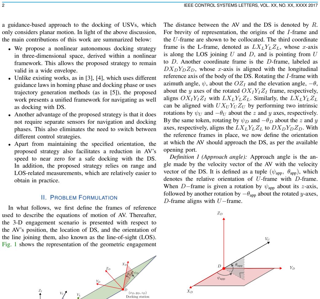
The central claim is that docking with a stationary station in 3D can be recast as a terminal-constraint guidance problem and solved by a single sliding-mode controller. The control law (29) inverts the kinematics matrix G — factored as diagonal G_R and orthogonal G_θ — to decouple the range, elevation, and azimuth error dynamics, then drives the sliding vector S = [Ṙ + k_R R, ė_θ + k_θ e_θ, ė_ψ + k_ψ e_ψ]ᵀ to zero in finite time. Once on the sliding manifold, the reduced dynamics are first-order linear, giving R→0 and LOS angles → desired approach angles. Simulations show speed dropping to near zero at docking.
Load-bearing premise
The control law inverts a matrix whose diagonal contains 1/(R cosθ); the paper does not prove the closed-loop trajectory keeps R>0 and cosθ≠0, so approaches from directly above or below the dock are not covered.
Editorial extensions
If this is right
- A unified guidance-and-control law replaces the separate homing and docking phases used by earlier methods, eliminating mode-switching logic.
- Only range and line-of-sight measurements are needed, reducing sensor and computation requirements for real docking systems.
- The finite-time convergence bound (32) depends explicitly on controller gains and initial conditions, so designers can tune a guaranteed settling time.
- The same controller applies across underwater, aerial, spacecraft, and mobile-robot docking scenarios with a stationary dock.
- Near-zero speed at the contact point is achieved by construction, mitigating collision risk during the final approach.
Reading between the lines
- The formulation effectively maps docking into an impact-angle guidance problem; the same structure may extend to moving or floating docking stations by adding the station's velocity kinematics.
- The singular geometry at line-of-sight elevation θ = ±90° (vehicle directly above or below the dock) is not addressed; a quaternion-based LOS parametrization or a temporarily rotated reference frame would be a natural fix.
- The finite-time guarantee applies to the sliding surface, while the physical range R→0 is only asymptotic (exponential); in practice a handover or threshold rule may be needed once R is small.
- The boundedness argument near the dock relies on the lead angles θ_U, ψ_U reaching zero before R does; this ordering is inferred from the reduced-order dynamics but is not proven for all transient states, so departure from that ordering could create large control spikes.
Signed reviews
Editorial analysis
A structured set of objections, weighed in public.
Referee Report
Summary. The paper proposes a three-dimensional sliding-mode guidance strategy for docking an autonomous vehicle with a stationary docking station. The vehicle is required to approach the docking station at a prespecified approach angle while reducing its speed to near zero. The authors derive relative-motion kinematics in polar coordinates, define sliding surfaces on range rate and line-of-sight angle errors, and prove via a Lyapunov analysis that the sliding surface converges to zero in finite time; on the sliding manifold, the range and LOS angles converge asymptotically to their desired values. MATLAB simulations demonstrate the proposed law for several initial vehicle positions, docking-station positions, and approach angles.
Significance. The kinematic derivation and Lyapunov finite-time convergence argument in Sections III-A to III-C are coherent and largely self-contained. The control law (29) is derived from first principles without fitted parameters, and the paper honestly reports the asymptotic nature of the reduced-order dynamics on the sliding manifold. If the unresolved singular-geometry issue and the unproven time-scale separation in Section III-D were properly addressed, the strategy would be a useful unified guidance method requiring only range and LOS measurements. However, the paper's stated claim of docking from 'various initial locations and orientations' is currently too broad: the control law is undefined at LOS elevation ±90°, and the boundedness argument near the docking station rests on an unverified ordering assumption. These gaps are load-bearing and must be closed or the problem statement must be restricted.
major comments (2)
- [Sec. III-B to III-C, Eq. (28)] The control law (29) is defined only where G is invertible. From the decomposition in (26), G = G_R G_θ, with G_R = diag(1, 1/R, 1/(R cosθ)), so G is singular when R = 0 or cosθ = 0. The paper never proves that the closed-loop trajectory avoids these sets. The kinematics themselves, (3) and (18), contain 1/cosθ, and the LOS elevation can reach ±90° for a docking station directly above or below the vehicle. Since Problem 1 and the abstract claim docking for 'various initial locations and orientations' without excluding these geometries, the central claim is not established for vertical docking configurations. The authors should either characterize the domain of nonsingular operation and prove invariance of that domain, or reformulate the controller in singularity-free coordinates (e.g., quaternions) and adjust the claims accordingly.
- [Sec. III-D, Eq. (37)] The boundedness of G^{-1}F near the docking station is justified by the statement that θ_U and ψ_U 'go to zero before R→0'. This is not proven. After finite-time convergence of S, the reduced-order dynamics give R(t), e_θ(t), e_ψ(t) as exponentials with rates k_R, k_θ, k_ψ, but θ_U and ψ_U are not the same as the LOS angle errors; no rate comparison is supplied. Moreover, the simulation parameters in Section IV use k_R = 1 and k_θ = k_ψ = 0.1, so the range decays faster than the LOS angle errors—the opposite of what the boundedness argument would require if interpreted literally. Since (37a)-(37c) contain 1/R factors, the finiteness of the control input near docking is not established. A quantitative bound, or a gain condition such as k_θ, k_ψ ≫ k_R plus an estimate of the time needed for orientation alignment, is needed.
minor comments (5)
- [Sec. II, Definition 1] Definition 1 defines the approach angle relative to the 'velocity vector of the DS', but the DS is stationary. The mathematical statement in Problem 1 correctly uses the DS-attached frame. Please reconcile the wording.
- [Sec. IV] There is a typo: 'A V is positions are three different initial locations' should be 'A V is positioned at three different initial locations'.
- [Sec. I] There is a stray '[?]' before reference [7] in the sentence about spacecraft docking.
- [Sec. III-D] The informal statement 'The A V first aligns itself at the desired orientation before R→0' should be stated as a lemma with a proof; as written it is an assertion, and the paper's subsequent boundedness conclusion depends on it.
- [Fig. 3-5] In several figure labels, the subscripts for θ and ψ appear as '3' and 'A' (e.g., '3F = -45°', 'AF = 10°'); these should be corrected to θ_F and ψ_F.
Circularity Check
No significant circularity: the docking strategy is derived from first-principles relative-motion kinematics and a standard finite-time sliding-mode construction; self-citations are contextual only.
full rationale
The derivation chain is self-contained. Equations (1)-(6) are the kinematic model; (20) defines sliding surfaces that encode the docking objective; (23)-(29) algebraically compute the control that makes ḊS equal to a signed fractional-power dissipation term. Substituting (29) into (21) gives (30), and the finite-time bound (32) follows from the comparison inequality (31). None of these steps assumes the conclusion: convergence of S is proven, not postulated, and on S=0 the reduced dynamics Ḋz = -k_i z give R→0 and LOS errors →0. No parameter is fitted to simulation data and then renamed a prediction; the gains in Section IV are selected controller constants. The references [13]-[17], including prior work by the present authors, are cited as related work and motivation; no uniqueness theorem, ansatz, or fitted result is imported from them, so the self-citations are not load-bearing. The reviewer-flagged singularity of G (Eqs. 25-28) when R=0 or cosθ=0, and the informal claim in Section III-D that the vehicle "first aligns itself... before R→0," are correctness/domain-of-validity concerns, not circularity: even if the proof does not cover those geometries, the claimed result is not equivalent to its inputs by construction.
Assumptions & free parameters
free parameters (1)
- Controller gains (k_R, k_θ, k_ψ, M_R, M_θ, M_ψ, N_R, N_θ, N_ψ, α) =
1, 0.1, 0.1, 0.0317, 0.6963, 0.7, 0.0766, 0.0178, 0.01, 0.9
assumptions (4)
- standard math The 3D engagement kinematics (Eqs. 1–6) describe the vehicle–DS relative motion in polar coordinates.
- domain assumption The vehicle is fully actuated with unlimited control authority (a_Ux, a_Uy, a_Uz).
- domain assumption R cos θ ≠ 0 along the trajectory so that G⁻¹ exists.
- ad hoc to paper The AV aligns its velocity to the LOS (θ_U, ψ_U → 0) before R → 0.
Cite this review
Pith. "Pith review of Docking of Autonomous Vehicles with a Stationary Docking Station in 3D Space." pith.science (2026). https://pith.science/paper/4GCIVNZD
@misc{pith2026260702478,
  author       = {Pith},
  title        = {Pith review of: Docking of Autonomous Vehicles with a Stationary Docking Station in 3D Space},
  year         = {2026},
  howpublished = {\url{https://pith.science/paper/4GCIVNZD}},
  note         = {Machine review of arXiv:2607.02478}
}
read the original abstract
In this letter, we present a strategy for autonomous docking of autonomous vehicles in three-dimensional space. Docking is a safety-critical task and requires expert piloting skills. Vehicles with autonomous docking capabilities are highly desirable in various applications, such as marine vehicle docking, aerial vehicle docking, spacecraft docking, and landing. To dock autonomously with the docking station, the vehicle must align itself to a specific desired orientation relative to the docking station and also reduce speed as it approaches. The vehicle achieves near-zero speed to dock successfully and safely without colliding with the docking station. Inspired by the philosophies from the guidance literature, we present a finite-time sliding mode-based strategy to achieve the same. The range and line-of-sight kinematics relations describing the motion of the vehicle with respect to the stationary docking station are used to steer the vehicle to achieve the desired orientation for docking. This docking strategy is validated in MATLAB\textsuperscript{\textregistered} simulations for various initial locations and orientations of both the vehicle and the docking station.
Figures


Figures from the paper (5 more)


Reference graph
Works this paper leans on
-
[1]
Tracking control of docking maneuvers for a fully actuated surface vessel using backstepping,
L. M. Kinjo, T. M ´enard, S. Wirtensohn, O. Gehan, and J. Reuter, “Tracking control of docking maneuvers for a fully actuated surface vessel using backstepping,”IEEE Transactions on Control Systems Technology, vol. 32, no. 5, pp. 1920–1927, 2024
1920
-
[2]
AUV homing and docking for remote operations,
N. Palomeras, G. Vallicrosa, A. Mallios, J. Bosch, E. Vidal, N. Hurtos, M. Carreras, and P. Ridao, “AUV homing and docking for remote operations,”Ocean Engineering, vol. 154, pp. 106–120, 2018
2018
-
[3]
Autonomous underwater vehicle docking system for cabled ocean observatory network,
D.-j. Li, Y .-h. Chen, J.-g. Shi, and C.-j. Yang, “Autonomous underwater vehicle docking system for cabled ocean observatory network,”Ocean Engineering, vol. 109, pp. 127–134, 2015
2015
-
[4]
AUV docking experiments based on vision positioning using two cameras,
Y . Li, Y . Jiang, J. Cao, B. Wang, and Y . Li, “AUV docking experiments based on vision positioning using two cameras,”Ocean Engineering, vol. 110, pp. 163–173, 2015
2015
-
[5]
Robust aerial docking in carrier-centered frame: A relative state-based approach,
X. Dong, Y . Cui, D. Li, B. Yang, J. Xiang, and Z. Tu, “Robust aerial docking in carrier-centered frame: A relative state-based approach,” IEEE Robotics and Automation Letters, vol. 11, no. 2, pp. 1802–1809, 2026
2026
-
[6]
Real-time autonomous spacecraft proximity maneuvers and docking using an adap- tive artificial potential field approach,
R. Zappulla, H. Park, J. Virgili-Llop, and M. Romano, “Real-time autonomous spacecraft proximity maneuvers and docking using an adap- tive artificial potential field approach,”IEEE Transactions on Control Systems Technology, vol. 27, no. 6, pp. 2598–2605, 2019
2019
-
[7]
Robust model predictive control for spacecraft rendezvous under sector-bounded non- linearities,
´A. M. Bokor, F. Biert ¨umpfel, P. Seiler, and R. T ´oth, “Robust model predictive control for spacecraft rendezvous under sector-bounded non- linearities,”IEEE Control Systems Letters, vol. 9, pp. 2567–2572, 2025
2025
-
[8]
Guaranteed safe spacecraft docking with control barrier functions,
J. Breeden and D. Panagou, “Guaranteed safe spacecraft docking with control barrier functions,”IEEE Control Systems Letters, vol. 6, pp. 2000–2005, 2022
2000
Show all 17 references
-
[9]
Three-dimensional mobile docking control method of an underactuated autonomous underwater vehicle,
T. Xie, Y . Li, Y . Jiang, S. Pang, and X. Xu, “Three-dimensional mobile docking control method of an underactuated autonomous underwater vehicle,”Ocean Engineering, vol. 265, p. 112634, 2022
2022
-
[10]
Autonomous underwater vehicle docking,
J. G. Bellingham, “Autonomous underwater vehicle docking,” in Springer Handbook of Ocean Engineering, ser. Springer Handbooks, M. R. Dhanak and N. I. Xiros, Eds. Springer, 2016, pp. 387–406
2016
-
[11]
A USV-based automated launch and recovery system for AUVs,
E. I. Sarda and M. R. Dhanak, “A USV-based automated launch and recovery system for AUVs,”IEEE Journal of Oceanic Engineering, vol. 42, no. 1, pp. 37–55, 2017
2017
-
[12]
Au- tonomous docking of hovering type AUV to seafloor charging station based on acoustic and visual sensing,
Y . Sato, T. Maki, K. Masuda, T. Matsuda, and T. Sakamaki, “Au- tonomous docking of hovering type AUV to seafloor charging station based on acoustic and visual sensing,” in2017 IEEE Underwater Technology (UT), 2017, pp. 1–6. 7 0 5 Z (m) 0 10 X (m) 5 10 Y (m) 10 50 P1 P2 P3 (a)...
2017
-
[13]
Three-dimensional impact angle guidance with coupled engagement dynamics,
S. R. Kumar and D. Ghose, “Three-dimensional impact angle guidance with coupled engagement dynamics,”Proceedings of the Institution of Mechanical Engineers, Part G: Journal of Aerospace Engineering, vol. 231, no. 4, pp. 621–641, 2017
2017
-
[14]
Spatial nonlinear guidance strategies for target interception at pre-specified orientation,
R. V . Nanavati, S. R. Kumar, and A. Maity, “Spatial nonlinear guidance strategies for target interception at pre-specified orientation,”Aerospace Science and Technology, vol. 114, p. 106735, 2021
2021
-
[15]
Three-dimensional impact angle constrained nonlinear guidance with predefined convergence time,
K. Majumder and S. R. Kumar, “Three-dimensional impact angle constrained nonlinear guidance with predefined convergence time,” Nonlinear Dynamics, vol. 112, no. 12, pp. 9983–10 008, 2024
2024
-
[16]
Quaternion-based non-singular nonlinear impact angle guidance for three-dimensional engagements,
P. Surve, A. Maity, and S. R. Kumar, “Quaternion-based non-singular nonlinear impact angle guidance for three-dimensional engagements,” Aerospace Science and Technology, vol. 155, p. 109657, 2024
2024
-
[17]
Autonomous docking of uncrewed surface vessel with stationary and moving ships,
R. M. K. Verma, S. R. Kumar, and H. Arya, “Autonomous docking of uncrewed surface vessel with stationary and moving ships,”Journal of Guidance, Control, and Dynamics, vol. 49, no. 6, pp. 1860–1869, 2026
2026
Reviewed August 2, 2026 · model on record in the stance chip above.
Discussion (0). Continue with ORCID to comment.