REVIEW 2 major objections 5 minor 15 references
Design and Commissioning of Readout Electronics for a $K_L^0$ and $\mu$ Detector at the Belle II Experiment
T0 review · 2 major / 5 minor · reviewed 2026-08-09 · deepseek-v4-flash
Pith's one-line read Belle II's outer detector readout, built around a 1 GHz waveform-sampling ASIC, was installed and commissioned to meet the 30 kHz trigger rate.
desk verdict A solid, workmanlike commissioning report for the Belle II KLM readout; the firmware-resident SPS method is the real novelty, and the main soft spot—the unverifiable 30 kHz simulation claim—is worth a referee's attention but not a rejection. read the letter →
The pith
A machine-rendered reading of the paper's core claim, the machinery that carries it, and where it could break.
The reading
What carries the argument
The load-bearing object is the readout chain rather than any single chip: the TARGETX ASIC (a 16-channel, 1 GHz waveform-sampling chip with 214 storage cells per channel and a per-channel trigger comparator), the SCROD FPGA board that controls up to ten such ASICs, handles L0 self-triggers and L1 lookback, and performs feature extraction, and the Data Concentrator that merges scintillator and RPC hit packets. The feature-extraction stage uses constant-value discrimination with linear interpolation to define leading-edge time because the preamplifiers saturate on large pulses, so constant-fraction discrimination is impossible. A second essential mechanism is the in-firmware single-photon spectrum: dark-rate pulses are histogrammed inside FPGA block RAM, each spectrum is fit to a sum of Gaussians spaced by the gain, and the gain-versus-bias linear fit is used to trim each SiPM's bias in 20 mV steps. Together these mechanisms carry the paper's two claims: the system keeps pace with 30 kHz triggers, and the SiPMs are uniformly calibrated without calibration sources.
What would settle it
Measure leading-edge arrival time as a function of pulse amplitude on a single scintillator strip using the TARGETX waveforms: if the time of the leading edge at a fixed threshold shifts by more than about 1 ns between single-photoelectron and saturated multi-photoelectron pulses on the same channel, the constant-$T_\mathrm{collect}$ assumption fails and the reported resolution would change after an amplitude-dependent correction. A simpler version: compute the $t_0$ residual distribution before and after adding a pulse-height-dependent term to the timing model; if the width shrinks, the constant assumption was the limiting factor.
Extended reading notes
Core claim
The central discovery is that the full KLM readout system works as designed: it was installed and commissioned, and it satisfies the Belle II unified-readout requirement of sustaining a 30 kHz L1 trigger rate. Waveform digitization of silicon-photomultiplier signals is performed by the TARGETX ASIC, which samples at 1 GHz into a 16.384 µs analog buffer per channel; the SCROD FPGA timestamps self-triggers, masks regions of interest on L1, digitizes, subtracts per-cell pedestals, and extracts leading-edge time and pulse height. The system merges these scintillator data with timestamps from RPC front-end boards in a Data Concentrator. The authors further report that all 18,560 installed SiPMs were gain-calibrated without any calibration light source by recording dark-rate single-photon spectra inside the firmware; more than 17,000 channels were then set to a common gain. Per-strip cable-delay calibration in the Belle II conditions database yields the reported hit-time resolutions, with the paper noting that the charge-collection time in the SiPM is currently treated as a small constant.
Load-bearing premise
The timing calibration treats the SiPM charge-collection time $T_\mathrm{collect}$ as a small constant independent of pulse height and the number of pixels fired; if it actually varies with pulse amplitude, the reported 4.7–7.8 ns hit-time resolutions and the per-strip calibration constants would be systematically biased.
Editorial extensions
If this is right
- The SCROD firmware can sustain Belle II's design L1 trigger rate of 30 kHz (Poisson-distributed, 200 ns minimum spacing), so the waveform-readout architecture is not a bottleneck at design luminosity.
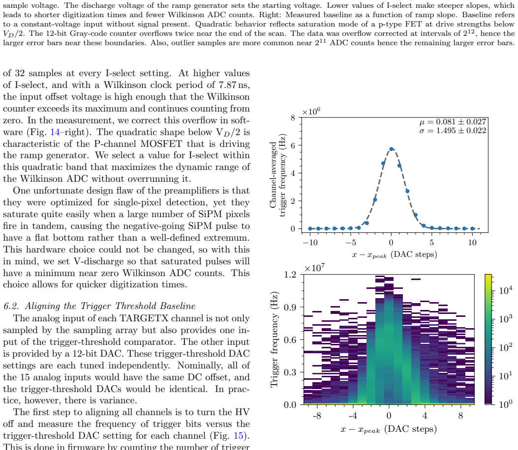
- At the early-2024 luminosity of $1.9\times10^{34}\,\mathrm{cm^{-2}s^{-1}}$ and a 2.8 kHz L1 rate, only 0.4% of hits skip waveform digitization, meaning multi-channel ambiguity is resolved for essentially all events.
- Waveform digitization disambiguates multi-channel hits on a single TARGETX: without it, group hits degrade strip resolution from 4 cm to 16 cm; with it, normal strip-level resolution is restored.
- Per-strip cable-delay calibration gives hit-time resolutions of 7.8 ns (RPC), 5.4 ns (barrel scintillator), and 4.7 ns (endcap scintillator), which are the input to track and K-long cluster reconstruction.
- The gain of more than 17,000 SiPMs was set to a common value (target 30 ADC counts per photoelectron), making trigger thresholds and pulse-height comparisons uniform across the detector.
Reading between the lines
- The dark-rate single-photon-spectrum calibration, done entirely in firmware without calibration sources, is a transferable recipe for large SiPM arrays where LED or laser calibration would be impractical.
- If the charge-collection time $T_\mathrm{collect}$ varies with pulse amplitude more than the paper assumes, the timing constants would need an amplitude-dependent term; this can be tested by comparing leading-edge times for single- versus multi-photoelectron pulses on the same strip.
- The fixed-latency lookback scheme with a digitization queue and a fallback 'simple mode' (timestamp-only, zero pulse height) is a general pattern for front-end readout at high-rate colliders, since it bounds dead time under bursty triggers.
- The paper's anticipated improvement toward about 1 ns hit-time resolution, if realized by better feature extraction, would directly strengthen background rejection and low-momentum muon identification at design luminosity.
Signed reviews
Editorial analysis
A structured set of objections, weighed in public.
Referee Report
Summary. This paper reports the design, firmware development, calibration, and commissioning of the readout electronics for the K_L^0 and muon (KLM) detector of Belle II. The system comprises a scintillator readout chain based on TARGETX waveform-sampling ASICs and SCROD FPGA boards, an RPC front-end with TDC timestamping, and a Data Concentrator that merges both streams. The paper also describes an in-situ calibration procedure that uses single-photon spectra recorded in firmware to homogenize the gain of more than 17,000 SiPMs without dedicated calibration sources, and it reports measured hit-time resolutions from early 2024 data: standard deviations of 7.8 ns for RPCs, 5.4 ns for barrel scintillators, and 4.7 ns for endcap scintillators. The central claim is that the full readout system was successfully designed, installed, and commissioned and that it meets the Belle II requirement of sustaining a 30 kHz L1 trigger rate.
Significance. If the claims hold, this is a valuable instrumentation paper for a major running experiment. It documents a complete, working readout chain for two detector technologies with a single Data Concentrator, and it demonstrates a practical method for calibrating tens of thousands of SiPMs without calibration sources. The reported in-situ gain homogenization and the measured timing resolutions are concrete performance results that will be useful to the Belle II collaboration and to future detector projects. The paper's strengths include the explicit use of real commissioning data, the statement of measured digitization-skip rates, and the discussion of known limitations such as preamplifier saturation. However, two load-bearing quantitative claims—the 30 kHz trigger-rate capability and the timing-resolution numbers—rest on assumptions that are not fully substantiated in the manuscript.
major comments (2)
- [3.2, 3.3, 3.4, 8] The sentence in §3.2 that 'Simulation tests verify that this scheme allows the SCROD firmware to keep pace with a 30 kHz L1 trigger rate (Poisson-distributed with a minimum of 200 ns between consecutive L1 triggers), the requirement for Belle II unified readout-system design' is the only support for the conclusion that the system operates 'at trigger rates up to 30 kHz.' The simulation is not described: no firmware version, no traffic model, no treatment of the SRAM bottleneck identified in §3.4, and no validation against the measured 2.8 kHz data with 0.4% digitization skips. Because the SRAM access is explicitly stated to become the bottleneck for multi-channel hits, and because the 'simple mode' in §3.2 skips waveform digitization entirely, it is essential to know how the simulation modeled these effects. Please provide a fuller description of the simulation (or a reference to a public note), or substantiate the 30 kHz capability with a bench or beam test, or soften the claim to 'designed for 30 kHz' with the simulation presented as indicative. As written, this load-bearing claim cannot be independently assessed.
- [7, Eq. (1)] In the definition of t0, the term Tcollect is described as 'small and currently treated as a constant,' but no evidence is given that its variation with pulse height (i.e., number of fired SiPM pixels) is negligible. If Tcollect varies with pulse amplitude, the per-strip calibration constants (Tcable) fitted from the same data could absorb part of this variation, and the quoted standard deviations (7.8 ns for RPCs, 5.4 ns for barrel scintillators, 4.7 ns for endcap scintillators) could underestimate the true timing resolution. Please either demonstrate that Tcollect variation is small by, for example, comparing t0 in bins of pulse height, or explicitly state in the conclusions that the quoted resolutions assume a constant Tcollect and may be optimistic. This is load-bearing for the quantitative performance results.
minor comments (5)
- [7] The sentence 'The t0 resolutions (FWHMs) for RPCs, barrel scintillators, and endcap scintillators are 7.8 ns (14.0 ns), 5.4 ns (5.6 ns), and 4.7 ns (3.8 ns), respectively' is confusing because the numbers in parentheses are FWHMs but the phrase 'resolutions (FWHMs)' implies the first numbers are also FWHMs. Suggest rewording to 'The standard deviations (FWHMs) are 7.8 ns (14.0 ns), 5.4 ns (5.6 ns), and 4.7 ns (3.8 ns), respectively.'
- [6.4] The text states 'The mean gain slope is 15 ADC counts / PE / V,' while the example fit in Fig. 18 yields a slope of 14.01 ADC counts / PE / V. Please clarify whether 15 is a rounded average over all channels or a different quantity, and consider quoting the distribution mean with uncertainty.
- [3.2] The phrase 'Poisson-distributed with a minimum of 200 ns between consecutive L1 triggers' is ambiguous because a true Poisson process has no minimum inter-arrival time. Presumably the simulated trigger stream is Poisson subject to a 200 ns dead-time or spacing constraint; please specify the model precisely.
- [6.3] The sentence 'According to the SiPM vendor, at a 70 V bias, the frequency of SiPM pulses larger than 1.2 pixels is 75 kHz, and 750 kHz for 0.5 pixels, respectively' is awkward; rephrasing as two separate statements would improve clarity.
- [7] The t0 definition is presented as a displayed equation but is not numbered. In the journal version, numbered equations would facilitate reference.
Circularity Check
No significant circularity: the paper is a commissioning report whose timing resolution is internally calibrated but not forced by construction; the 30 kHz claim rests on an undocumented simulation, not on a circular reduction.
full rationale
The paper reports hardware/firmware design, commissioning, and calibrations; it does not claim to derive a predicted quantity from fitted inputs. The only fitted quantities are per-strip cable-delay offsets and per-SiPM gain-tuning DAC settings. The t0 resolution in Section 7 is computed after subtracting per-strip Tcable constants fitted from the same data; this is self-calibration, but subtracting a per-strip mean removes only constant offsets and cannot force the reported standard deviations (7.8, 5.4, 4.7 ns) to zero. The paper explicitly acknowledges that the calibration algorithm itself contributes to the tails, so no residual is presented as an independent prediction. The 30 kHz L1-rate capability in Section 3.2 is asserted on the basis of undisclosed simulation tests and is therefore an evidence/completeness concern, not a circular one: the requirement is cited to the Belle II unified readout reference [10], and no equation of the present paper is used as its own input. The assumption that Tcollect is a small constant in Section 7 is a stated physical approximation that affects timing accuracy but is not a circular definition. SiPM gain homogenization uses single-photon-spectrum fits and linear gain-versus-bias calibrations to set HV-trim DACs; this is a direct calibration loop, not a fitted parameter renamed as a prediction. No load-bearing self-citation chain or uniqueness import was found; references to TARGET development and Belle II readout requirements are external engineering context. Thus the central claims have independent content, and no circular step can be exhibited with a specific equation-to-equation reduction.
Assumptions & free parameters
free parameters (3)
- Trigger threshold DAC offset of 35 steps below baseline =
35 DAC steps
- Per-strip cable delay calibration constant T_cable =
Gaussian mean per strip
- SPS fit parameters (crosstalk chi, pedestal offset x0, sigma0, sigma1, amplitude A, peak spacing a0) =
Fit-dependent per channel
assumptions (3)
- domain assumption SiPM dark rate and crosstalk behavior follow a power-law model suitable for gain extraction
- domain assumption The TARGETX ASIC operates as documented, including 16.384 microseconds of analog storage, 1 GHz sampling, and the Wilkinson ADC response
- domain assumption The CDC-based EventT0 and extrapolated flight time provide a sufficiently accurate reference for KLM time calibration
Cite this review
Pith. "Pith review of Design and Commissioning of Readout Electronics for a $K_L^0$ and $\mu$ Detector at the Belle II Experiment." pith.science (2026). https://pith.science/paper/5NXMGULX
@misc{pith2026250202724,
  author       = {Pith},
  title        = {Pith review of: Design and Commissioning of Readout Electronics for a $K_L^0$ and $\mu$ Detector at the Belle II Experiment},
  year         = {2026},
  howpublished = {\url{https://pith.science/paper/5NXMGULX}},
  note         = {Machine review of arXiv:2502.02724}
}
read the original abstract
The K-long and muon detector (KLM) constitutes the outer-most volume of the Belle II spectrometer at the interaction region of the SuperKEKB collider in Tsukuba, Japan. The KLM detector was partially upgraded since the Belle experiment by replacing many of its resistive-plate chambers with scintillators containing wavelength-shifting fibers and instrumenting it with silicon photomultipliers. We describe the readout electronics, firmware, and software created to control and acquire data from the scintillators and resistive-plate chambers.
Figures


Figures from the paper (15 more)




Reference graph
Works this paper leans on
-
[1]
Abe et al., Belle II technical design report (2010)
T. Abe et al., Belle II technical design report (2010). arXiv: 1011.0352
arXiv 2010
-
[2]
A. Abashian et al. (The Belle Collaboration), The Belle de- tector, Nucl. Instrum. Methods A 479 (1) (2002) 117–232. doi:https://doi.org/10.1016/S0168-9002(01)02013-7
-
[3]
J. G. Wang, RPC performance at KLM/BELLE, Nucl. Instrum. Methods A 508 (2003) 133–136. doi:10.1016/S0168-9002(03) 01335-4
-
[4]
Aushev et al., A scintillator based endcap K L and muon detector for the Belle II experiment, Nucl
T. Aushev et al., A scintillator based endcap K L and muon detector for the Belle II experiment, Nucl. Instrum. Methods A 789 (2015) 134 – 142. doi:10.1016/j.nima.2015.03.060
- [5]
-
[6]
K. Bechtol et al., TARGET: A multi-channel digitizer chip for very-high-energy gamma-ray telescopes, Astroparticle Physics 36 (1) (2012) 156–165. doi:10.1016/j.astropartphys.2012. 05.016
-
[7]
L. Tibaldo et al., TARGET: toward a solution for the readout electronics of the cherenkov telescope array (2015).arXiv:1508. 06296
work page 2015
-
[8]
S. Funk et al., TARGET: A digitizing and trigger ASIC for the Cherenkov telescope array, in: AIP Conference Proceedings,
Show all 15 references
-
[9]
Albert et al., TARGET 5: A new multi-channel digi- tizer with triggering capabilities for gamma-ray atmospheric cherenkov telescopes, Astroparticle Physics 92 (2017) 49–61
A. Albert et al., TARGET 5: A new multi-channel digi- tizer with triggering capabilities for gamma-ray atmospheric cherenkov telescopes, Astroparticle Physics 92 (2017) 49–61. doi:10.1016/j.astropartphys.2017.05.003
2017 doi
-
[10]
Nakao et al., Performance of the unified readout system of Belle II, IEEE Transactions on Nuclear Science 68 (8) (2021) 1826–1832
M. Nakao et al., Performance of the unified readout system of Belle II, IEEE Transactions on Nuclear Science 68 (8) (2021) 1826–1832. doi:10.1109/TNS.2021.3084826
2021
-
[11]
Edralin, Design and performance of an automated pro- duction test system for a 20,000 channel single-photon, sub- nanosecond electronic readout for a large area muon detector, Ph.D
B. Edralin, Design and performance of an automated pro- duction test system for a 20,000 channel single-photon, sub- nanosecond electronic readout for a large area muon detector, Ph.D. thesis, University of Hawai‘i, Honolulu (11 2016)
2016
-
[12]
Ritter et al., Belle II conditions database, J
M. Ritter et al., Belle II conditions database, J. Phys.: Conf. Ser. 1085 (2018). doi:10.1088/1742-6596/1085/3/032032
2018 doi
-
[13]
T. Kuhr, C. Pulvermacher, M. Ritter, T. Hauth, N. Braun, The Belle II core software: Belle II framework software group, Computing and Software for Big Science 3 (1) (Nov. 2018).doi: 10.1007/s41781-018-0017-9
2018 doi
-
[14]
doi:10.5281/zenodo.6949513
The Belle II Collaboration, Belle II analysis software framework (basf2) (aug 2022). doi:10.5281/zenodo.6949513. 14
2022 doi
-
[2017]
doi:10.1063/1.4969033
Reviewed August 9, 2026 · model on record in the stance chip above.
Discussion (0). Continue with ORCID to comment.