REVIEW 3 major objections 5 minor 13 references
Design of the first sub-milligram flapping wing aerial vehicle
T0 review · 3 major / 5 minor · reviewed 2026-08-14 · deepseek-v4-flash
Pith's one-line read A 0.7 mg flapping-wing robot achieves insect-like wing motion.
desk verdict A real milestone in sub-milligram flapping kinematics wrapped in an unsupported 'aerial vehicle' claim — the lift estimate doesn't cover the mass, but the demonstrated mechanism deserves refereeing. read the letter →
The pith
A machine-rendered reading of the paper's core claim, the machinery that carries it, and where it could break.
The reading
What carries the argument
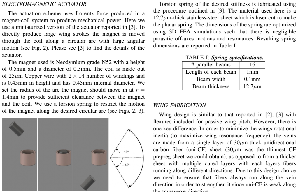
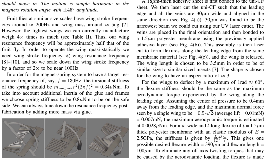
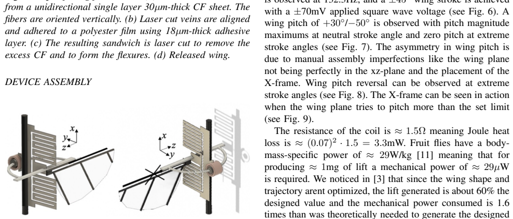
The device is built around a moving-magnet electromagnetic actuator: a small N52 neodymium magnet travels along a circular arc through a fixed copper coil under Lorentz force, and a laser-cut stainless-steel torsion spring restores it and defines the arc. The wing attaches through a polyester flexure that allows passive wing pitch, and an X-shaped carbon-fiber frame limits the pitch amplitude by colliding with the central wing vein. This combination converts a 70 mV square-wave drive into the large angular stroke and pitch reversal that insect wings show, while keeping the entire mechanism to five glued components.
What would settle it
Measure the tethered device's lift directly with a sensitive microbalance or anemometer while driving the coil at 132.3 Hz with a $\pm 70$ mV square wave; if the single wing generates much less than the estimated 0.3 mg of lift, the transferred performance factors do not hold at this scale.
Extended reading notes
Core claim
The central claim is that an electromagnetic Lorentz-force actuator, scaled down in mass by two orders of magnitude from a 100 mg-class parent design, can still produce the large wing rotations needed for insect-like flapping. At a measured resonance of 132.3 Hz, the device shows a $90^\circ$ wing stroke amplitude and an $80^\circ$ wing pitch amplitude, with passive pitch reversal at the stroke extremes. Using lift and power performance factors measured on the larger actuator, the authors estimate that the single wing produces about 0.3 mg of lift with 23 µW of mechanical power, for an electromechanical efficiency near 0.7 percent. If these estimates hold, the 0.7 mg device is the lightest flapping-wing vehicle reported to date and sits at the mass scale where direct comparisons with insect flight become possible.
Load-bearing premise
The estimated lift and efficiency assume that the lift shortfall (60 percent of designed value) and mechanical power overhead (1.6 times theoretical) measured for the larger parent actuator transfer unchanged to this device, which is about one hundred times lighter in mass.
Editorial extensions
If this is right
- The 0.7 mg device with a single 3.5 mm wing is presented as the lightest flapping-wing vehicle reported to date, at the mass scale of a fruit fly.
- Demonstrated $90^\circ$ wing stroke and $80^\circ$ pitch amplitudes show that insect-like wing kinematics can be produced at sub-milligram scale.
- Low-voltage (70 mV) operation avoids the heavy, inefficient power electronics that hamper other milligram-scale robots, easing testing and eventual deployment.
- Five-component assembly from laser-cut parts increases fabrication speed and success rate relative to higher-part-count microrobots.
Reading between the lines
- The lift estimate depends entirely on performance factors measured at 100 mg scale, so the first test of the paper's headline numbers should be a direct sub-milligram lift measurement rather than further design iteration.
- Since the wing accounts for only 0.02 mg of the 0.7 mg total, the next meaningful mass reductions will have to come from the coil, magnet, and spring, not from the wing.
- The reported $+30^\circ/-50^\circ$ pitch asymmetry is attributed to manual assembly; automated alignment of the wing plane and X-frame would likely make the kinematics symmetric and could change the lift estimate.
- If the quasi-static operating point and passive pitch mechanism hold up, the same platform could serve as a testbed for fruit-fly-scale aerodynamics without requiring onboard pitch actuation.
Signed reviews
Editorial analysis
A structured set of objections, weighed in public.
Referee Report
Summary. The paper reports a 0.7 mg flapping-wing device consisting of an electromagnetic actuator, a torsion spring, and a single 3.5 mm wing, and demonstrates via strobe microscopy a ±45° wing stroke at 132.3 Hz resonance and a wing pitch range of +30°/−50° under a ±70 mV square wave drive. The authors estimate 0.3 mg of lift per wing and 0.7% electromechanical efficiency by scaling performance factors from their earlier 100 mg-scale actuator, and they explicitly state that they lacked the capacity to measure forces around 0.1 mg. The paper claims that this is the first sub-milligram flapping-wing aerial vehicle able to mimic insect wing kinematics.
Significance. If the kinematic observations are reliable, this is the lightest flapping-wing device with insect-like kinematics reported to date, at the mass scale of a fruit fly, and the simple five-component assembly and low-voltage operation are practical advances. The work also offers a platform for studying low-Reynolds-number aerodynamics at the fruit-fly scale. However, the 'aerial vehicle' status is not established by the data: the lift estimate is indirect, and the paper's own numbers imply that two wings would produce about 0.6 mg of lift, below the 0.7 mg device weight. The contribution should be reframed as a sub-milligram flapping-wing mechanism with demonstrated kinematics, with flight capability left as an open question pending direct lift measurement.
major comments (3)
- [Results (lift estimate) and Abstract/Title] The title and abstract describe this as an 'aerial vehicle,' but the only quantitative support for flight is an estimate, not a measurement: the Results section multiplies the parent actuator's performance factors from [3] (60% of designed lift, 1.6× mechanical power) onto a device two orders of magnitude lower in mass, with no scaling law or validation. Moreover, accepting the estimate, two wings would generate about 0.6 mg of lift (2 × 0.3 mg), which is below the measured net mass of 0.7 mg reported in Table II. The device as reported therefore cannot lift itself. Please either provide a direct lift measurement showing lift ≥ weight, or revise the title, abstract, and conclusion to describe a sub-milligram flapping-wing mechanism with insect-like kinematics rather than an aerial vehicle.
- [Methodology (wing flexure sizing)] The flexure stiffness calculation assumes an average lift of 0.01 mN (≈1 mg) per wing, using it to compute a maximum normal force of 0.007 mN and a desired flexure width of 390 µm. However, the Results estimate a single-wing lift of only 0.3 mg (≈0.003 mN). The factor-of-3.3 discrepancy is not addressed, and it matters because the flexure pitch amplitude depends on the ratio of aerodynamic torque to flexure stiffness. Please reconcile the lift value used in the design with the estimated lift, or explain why the flexure sizing remains valid under the lower load.
- [Results (kinematic measurements)] The central kinematic claims—±45° stroke (90° total), wing pitch range of 80°, resonance at 132.3 Hz, and the 70 mV operating voltage—are reported without repeated trials, error bars, or measurement uncertainty. Since these observations underpin the paper's main contribution, at least three to five repeated measurements on independent devices (or the same device over multiple trials) should be reported, along with the strobe/photography methodology used for angle extraction.
minor comments (5)
- [Conclusion] The statement that the device is '2 orders of magnitude lighter than all other flapping wing devices reported till date' is inaccurate given the 3 mg device cited as [5]; the device is sub-milligram, but the margin over [5] is less than an order of magnitude.
- [Introduction] The phrase 'operational voltages (70mV)' should specify that this is the amplitude of a square wave drive, not a DC voltage.
- [References] Reference [9] lists page numbers 1881-2044; the correct article (Dickinson et al., Science 284) spans pages 1954-1960.
- [Figures 6-9] The paper would benefit from scale bars in Figs. 6-9; while Fig. 1 includes a ruler, the motion snapshots lack scale annotations.
- [Abstract] The term 'wing span' is used without definition; for a single-wing device, clarify whether this refers to the single wing length or the full stroke envelope.
Circularity Check
No circularity: the kinematic demonstrations are measured, and the lift estimate is a transparent scaling assumption from prior work rather than a fitted or definitionally forced result.
full rationale
The paper's central observed results are direct measurements: the 90° wing stroke, +30°/−50° wing pitch, and 132.3 Hz resonance are strobe-microscope observations of the fabricated device, and the 0.7 mg mass is a component-by-component mass budget (Table II). The only candidate circular step is the lift/power estimate in the Results section: the paper imports the 60% lift and 1.6× power performance factors from the authors' prior IROS 2018 paper [3] and writes "We expect a similar behavior here since this work is a miniaturized version of [3]." That is a transparent extrapolation from an external measurement on the parent actuator, not a parameter fitted to this paper's data, and it is not presented as a measured outcome; the paper explicitly states "Presently we lacked the capacity to measure ≈ 0.1 mg lift forces." The estimated 0.3 mg lift is therefore a scaling prediction that is not independently validated in this paper, especially since the single-wing lift estimate is below the 0.7 mg device mass, but this is a correctness and evidentiary limitation rather than a circular derivation: no equation makes any claimed result equal to an input by construction, and the kinematic claims do not depend on the borrowed factor. The self-citations to [3] for actuator and spring design are ordinary engineering reuse, not a self-citation chain that forces the conclusions.
Assumptions & free parameters
free parameters (6)
- Target wing stroke frequency =
130 Hz
- Torsional spring stiffness =
0.8 µNm
- Flexure width and length =
390 µm x 100 µm (3 x 130 µm)
- Lift scaling factor =
0.6
- Mechanical power scaling factor =
1.6
- Wing length =
3.5 mm
assumptions (5)
- domain assumption Wing stroke frequency must be much lower than wing resonance frequency for quasi-static operation.
- ad hoc to paper Maximum normal force on a single wing equals 0.5*sqrt(2) times the average lift.
- ad hoc to paper Center of pressure is 0.4 mm from the leading edge.
- ad hoc to paper Performance factors from the parent actuator in [3] transfer to this scaled-down device.
- domain assumption Lorentz force actuator model from [3] is valid at this scale.
Cite this review
Pith. "Pith review of Design of the first sub-milligram flapping wing aerial vehicle." pith.science (2026). https://pith.science/paper/A4K3RNJT
@misc{pith2026190803203,
  author       = {Pith},
  title        = {Pith review of: Design of the first sub-milligram flapping wing aerial vehicle},
  year         = {2026},
  howpublished = {\url{https://pith.science/paper/A4K3RNJT}},
  note         = {Machine review of arXiv:1908.03203}
}
abstract
Here we report the first sub-milligram flapping wing vehicle which is able to mimic insect wing kinematics. Wing stroke amplitude of 90$^\circ$ and wing pitch amplitude of 80$^\circ$ is demonstrated. This is also the smallest wing-span (single wing length of 3.5mm) device reported yet and is at the same mass-scale as a fruit fly. Assembly has been made simple and requires gluing together 5 components in contrast to higher part count and intensive assembly of other milligram-scale microrobots. This increases the fabrication speed and success-rate of the fully fabricated device. Low operational voltages (70mV) makes testing further easy and will enable eventual deployment of autonomous sub-milligram aerial vehicles.
Figures

Figures from the paper (5 more)



Reference graph
Works this paper leans on
-
[3]
Bhushan and C.J
P. Bhushan and C.J. Tomlin, ``Milligram-scale Micro Aerial Vehicle Design for Low-voltage Operation,'' IROS , Madrid, Spain, Oct. 2018
2018
-
[1]
K. Ma, P. Chirarattanon, S. Fuller, and R.J. Wood, ``Controlled Flight of a Biologically Inspired, Insect-Scale Robot,'' Science , vol. 340, pp. 603-607, 2013
2013
-
[2]
R. J. Wood, ``Liftoff of a 60mg flapping-wing MAV,'' IROS, San Diego, CA, Oct. 2007
work page 2007
- [4]
-
[5]
N.T. Jafferis, E.F. Helbling, M. Karpelson, and R.J. Wood, ``Untethered Flight of an Insect-Sized Flapping-Wing Microscale Aerial Vehicle,'' Nature 570, 491-495, 2019
work page 2019
-
[6]
X. Yan, M. Qi, and L. Lin, ``Self-Lifting Artificial Insect Wings via Electrostatic Flapping Actuators,'' Proceedings of 28th IEEE Micro Electro Mechanical Systems Conference , pp. 22-25, Portugal, Jan. 2015
2015
-
[7]
I. Penskiy and S. Bergbreiter, ``Optimized electrostatic inchworm motors using a flexible driving arm,'' Journal of Micromechanics and Microengineering , Vol. 23, No. 1, pp 1-12, 2012
work page 2012
-
[8]
S. Vogel, ``Flight in Drosophila. I. Flight Performance of Tethered Flies,'' The Jour. Of Exp. Biol., 44: 567-578, 1966
work page 1966
Show all 13 references
-
[9]
S. P. Sane and M. H. Dickinson, ``The aerodynamic effects of wing rotation and a revised quasi-steady model of flapping flight,'' The Jour. of Exp. Biol., 205, 1087-1096, 2002
2002
-
[10]
M. H. Dickinson, F.-O. Lehmann, S. P. Sane, ``Wing rotation and the aerodynamics basis of insect flight,'' Science, vol. 284, pp. 1881-2044, 1999
1999
-
[11]
J. P. Whitney and R. J. Wood, ``Aeromechanics of passive rotation in flapping flight,'' J. Fluid Mech., vol. 660, pp. 197-220, 2010
2010
-
[12]
M. Sun, J. Tang, ``Lift and power requirements of hovering flight in Drosophila virilis,'' The Jour. Of Exp. Biol., 205: 2413-2427, 2002
2002
-
[13]
q 2 #B R 3br w !1 AQ aq
11em plus .33em minus .07em @technote 4000 4000 100 4000 4000 500 `\.=1000 = #1 #1 #1 0pt [0pt][0pt] #1 * \| ** #1 \@IEEEauthorblockNstyle \@IEEEauthorblockAstyle \@IEEEauthordefaulttextstyle \@IEEEauthorblockconfadjspace -0.25em \@IEEEauthorblockNtopspace 0.0ex \@IEEEauthorbl...
Reviewed August 14, 2026 · model on record in the stance chip above.
Discussion (0). Continue with ORCID to comment.