REVIEW 3 major objections 4 minor 32 references
Modeling of Ex-Situ Dissolution for Geologic Sequestration of Carbon Dioxide in Aquifers
T0 review · 3 major / 4 minor · reviewed 2026-08-14 · deepseek-v4-flash
Pith's one-line read Liquid CO2 carried by brine in a turbulent pipeline undergoes breakup, coalescence, and dissolution; this paper models all three in a population-balance framework and shows the computed droplet sizes match experimental data, making…
desk verdict A well-intentioned population-balance model for ex-situ CO2 dissolution, but the mass-transfer closure makes breakup irrelevant to total dissolution and the validation is a two-parameter fit. read the letter →
The pith
A machine-rendered reading of the paper's core claim, the machinery that carries it, and where it could break.
The reading
What carries the argument
The central object is the steady-state advection–diffusion population balance equation for the number concentration of droplets in each size class, discretized by the fixed-pivot method (a volume-conserving scheme that reallocates droplet volumes to fixed size classes). Breakup enters through a binary-breakup rate based on the Weber number with a critical value of 0.5; coalescence through a standard collision-frequency/coalescence-efficiency kernel; and dissolution through a convective mass-transfer rate set by the Sherwood-number correlation the paper adopts. The flow field is a two-region universal velocity profile, the droplet turbulent diffusivity follows an empirical eddy-diffusivity distribution across the pipe radius, and the turbulence energy dissipation rate is computed analytically from the pressure gradient. These closures let the equation evolve a polydisperse droplet population under realistically non-uniform turbulence, with the output collapsed to the Sauter diameter for comparison with data.
What would settle it
Measure the dissolution rate of individual liquid CO2 droplets in turbulent brine pipe flow at aquifer pressure and temperature (e.g., 70 bar, 25 °C) and compare the inferred Sherwood numbers with the correlation used in the model (Eq. 30). If the measured values differ systematically beyond experimental uncertainty, the dissolution rate is wrong regardless of how well breakup and coalescence are represented.
Extended reading notes
Core claim
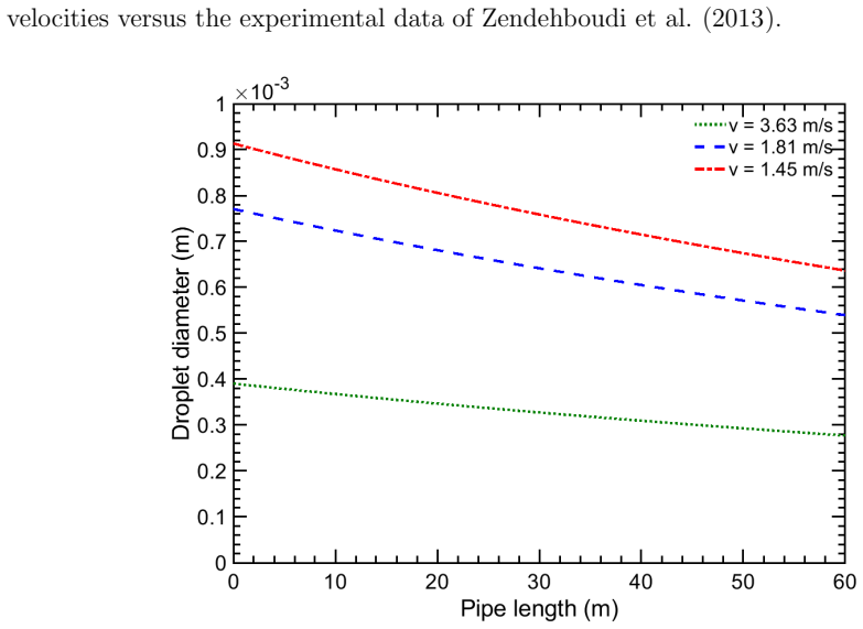
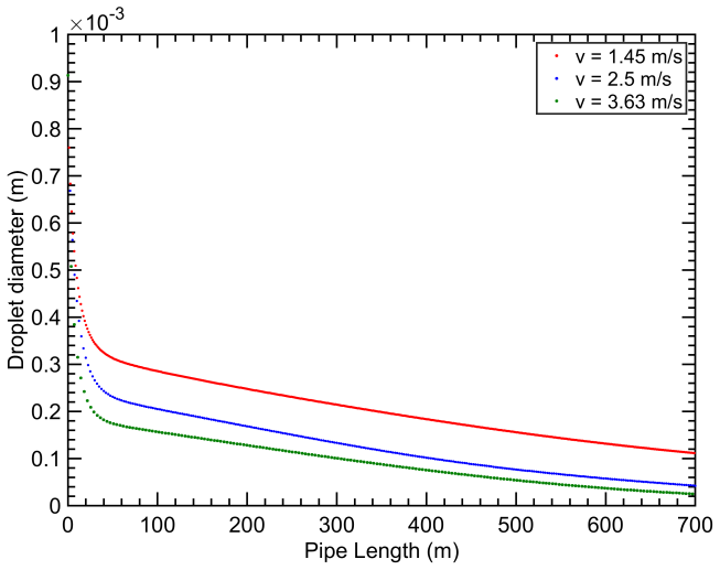
The discovery the paper argues for is that a single advection–diffusion population balance equation, with breakup and coalescence closures taken from earlier droplet dispersion work and a newly derived dissolution term, gives quantitatively correct Sauter diameters—the surface-area-weighted mean droplet size—for liquid CO2 droplets in brine along a turbulent pipeline. After tuning two free parameters, the breakup-rate prefactor and the coalescence-efficiency constant, to one experimental dataset at 70 bar and 25 °C with a 5% CO2 volume fraction, the computed Sauter diameters match the measured evolution along the pipe, with a tighter fit in the downstream half where the size distribution narrows. The paper further shows that a dissolution-only model without breakup and coalescence does not approach steady state on pipeline scales, which is why the full population balance matters. On this basis the paper claims the code can be used to design and optimize ex-situ dissolution systems.
Load-bearing premise
The load-bearing premise is that the Sherwood-number correlation the paper adopts, originally measured for gas bubbles in cocurrent water pipe flow, gives the correct mass-transfer coefficient for liquid CO2 droplets dissolving in brine; if that transfer does not hold, the predicted droplet sizes and dissolved CO2 concentrations are wrong even if breakup and coalescence are modeled perfectly.
Editorial extensions
If this is right
- If the model is correct, near-complete ex-situ dissolution becomes a design variable: for a fixed CO2 feed rate, engineers can choose brine flow velocity and pipe length so that droplet sizes shrink to very small values and dissolved CO2 approaches saturation before injection.
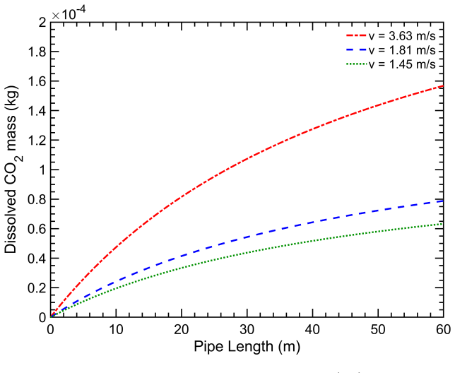
- Higher brine flow velocities accelerate dissolution through two mechanisms—a larger droplet-to-fluid mass-transfer coefficient and smaller breakup-limited droplets—so the model can identify the minimum flow rate that still meets a dissolution target.
- Higher initial CO2 droplet concentrations slow dissolution because the dissolved CO2 concentration approaches saturation faster, quantifying a direct trade-off between CO2 throughput and required pipeline length.
- The full population-balance approach replaces earlier mean-diameter estimates; it shows that ignoring breakup and coalescence leaves droplet sizes far from the steady state reached in real pipelines, so designs based on dissolution alone would be misleading.
Reading between the lines
- The Sherwood correlation transfer from gas bubbles to liquid CO2 droplets is an extrapolation; targeted single-droplet dissolution measurements would either support or overturn the model's mass-transfer rate.
- The two fitted parameters were tuned to one experimental dataset, so predictions at other salinities, temperatures, pressures, or pipe scales are extrapolations until those constants are measured independently for CO2–brine systems.
- The no-stratification assumption is checked for one operating point; in larger-diameter pipes or at lower velocities, gravity settling could break the model's radial uniformity assumption.
- The design loop could be automated: coupling the solver with an optimizer would map the Pareto frontier of pipe length versus brine flow rate for a target dissolution fraction.
Signed reviews
Editorial analysis
A structured set of objections, weighed in public.
Referee Report
Summary. The paper develops a steady-state advection-diffusion population balance model for CO2 droplet breakup, coalescence, and dissolution in a turbulent brine pipeline, intended for ex-situ carbon sequestration. The model is solved numerically with a fixed-pivot discretization and compared with Sauter-diameter measurements from Zendehboudi et al. (2013) by tuning two parameters, K in the breakup rate and C2 in the coalescence efficiency. The authors claim that the model is validated against available experimental data and can be used for design and optimization of ex-situ dissolution pipelines.
Significance. If the model were sound and properly validated, it would provide a useful engineering tool for designing ex-situ CO2 dissolution pipelines. The paper's numerical framework is standard, and the appendix derivation of the dissolution source term is a useful pedagogical contribution. However, two load-bearing problems prevent acceptance: the chosen mass-transfer correlation makes the total dissolution rate independent of droplet size, contradicting the paper's central claim that breakup accelerates dissolution; and the comparison with experiment is a fit of two free parameters to the same dataset, not a validation. These issues undermine the paper's main conclusions.
major comments (3)
- [Dissolution term, Eqs. (28)-(30)] Combining Eqs. (29) and (30) gives k = 0.34 (d_p Re^0.94 Sc^0.5 D_CO2)/D^2, so k is proportional to droplet diameter d_p. Substituting this into Eq. (28) yields (dx_i/dt)_diss proportional to x_i, meaning the fractional dissolution rate is identical for every size class and the total dissolution rate is proportional only to the dispersed-phase volume fraction. Consequently, the breakup and coalescence terms in Eq. (13) have no effect on the total amount of CO2 dissolved, contradicting the claim in the text following Fig. 3 that smaller droplets dissolve faster because of larger specific surface area. For the conditions cited in the paper (D=0.15 m, Re~5e5, Sc~530), a 150 micrometer droplet gives Sh~1.8 and a 100 micrometer droplet gives Sh~0.8, both at or below the stagnant-sphere limit Sh=2, further indicating that the correlation is not appropriate in this regime. The paper's central claim of breakup-accelerated dissolution is therefore not supported by its own equations.
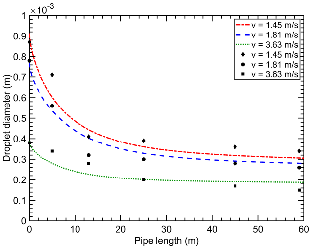
- [Results and discussion, Fig. 2] The agreement shown in Fig. 2 is obtained by tuning K in Eq. (16) and C2 in Eq. (26) to the same experimental dataset (K=0.1, C2=10^13). This is a curve fit, not a validation. The abstract's statement that the model is 'validated against available experimental data' and the later claim of 'significantly higher predictive capability' are therefore overstated. No independent test, holdout dataset, or uncertainty quantification is provided. At minimum, the paper should reframe the comparison as a calibration exercise and discuss the predictive limitations that follow from having two free parameters tuned to the single available dataset.
- [Dissolution term, Eq. (30)] The Kress and Keyes (1973) correlation was developed for gas bubbles in cocurrent water pipe flow. The authors do not justify its application to liquid CO2 droplets in brine. Since this correlation directly sets the mass-transfer coefficient and thus controls the entire dissolution dynamics, the transfer requires either independent experimental support or a sensitivity analysis over plausible alternative correlations. Without such support, the quantitative predictions in Figs. 4-7 are not reliable.
minor comments (4)
- [Eq. (30)] The symbol D is used for the pipe diameter in the geometric ratio (d_p/D)^2 and for the molecular diffusivity in the Schmidt number Sc = nu_f/D; this notation conflict should be resolved by using D_pipe and D_CO2.
- [Eq. (20)] The name 'Blausius' should be spelled 'Blasius'.
- [Abstract and Conclusion] The wording 'validated against available experimental data' is inconsistent with the body's statement that 'the computed Sauter diameter distributions were matched to the measured data by tuning the parameters'; the manuscript should be reworded to distinguish calibration from validation.
- [Results and discussion] The sentence 'the code presented here makes the optimization a rather straightforwardly handled task' implies that the code is available, but no code is provided; the authors should clarify the availability of the MATLAB implementation.
Circularity Check
Validation of droplet-size predictions is an in-sample fit: K and C2 are tuned to the same Zendehboudi et al. data that are then shown as agreement.
-
fitted input called prediction
[Results and discussion, after Eq. (31), Fig. 2; Conclusion]
"The computed Sauter diameter distributions along a pipe for different mean flow velocities at the initial mean droplet concentration φ0 = 0.05 were matched to the measured data by tuning the parameters K in Eq. (16) describing droplet breakup rate and C2 in Eq. (26) defining the coalescence probability. ... The best fitting was obtained at K = 0.1 and C2 = 10^13. One can see that the computational results correlate well with the measured data in Fig. 2."
The dataset used for validation (Zendehboudi et al., 2013) is the same dataset to which the model parameters K and C2 are fitted. K controls the breakup rate in Eq. (16) and C2 controls coalescence efficiency in Eq. (26); both directly set the evolution of the droplet size distribution and hence the Sauter diameter shown in Fig. 2. Matching the measured Sauter-diameter curves after tuning these two parameters is therefore a curve fit, not an independent prediction. The paper's conclusion that the model 'has been validated against the experimental data' and has 'significantly higher predictive capability' is unsupported by this in-sample agreement; no out-of-sample test is carried out.
full rationale
The advection-diffusion population-balance equation, the dissolution term derived in the Appendix, and the external closures (Johansen eddy diffusivity, Kress-Keyes Sherwood correlation, Coulaloglou-Tavlarides coalescence kernel) are independent inputs; using them is not circular. The breakup closure from Eskin et al. (2017a,b) is self-citational, but We_cr = 0.5 came from Couette experiments and is not the target result of this paper, so it does not by itself create circularity. The one clear circular step is the validation procedure: K and C2 are tuned to Zendehboudi et al.'s measured Sauter-diameter profiles, and the same profiles are then exhibited as agreement. This is a fitted input called a prediction. Whether the Kress-Keyes gas-liquid correlation transfers to liquid CO2 drops is a legitimate correctness/external-validity question, not a circularity question. Overall score 6: the central model structure contains independent content, but the headline validation claim reduces to an in-sample fit.
Assumptions & free parameters
free parameters (5)
- K (breakup rate coefficient, Eq. 16) =
0.1
- C2 (coalescence efficiency constant, Eq. 26) =
1e13 (dimensional)
- C1 (coalescence frequency constant, Eq. 25) =
1.0
- We_cr (critical Weber number, Eq. 16) =
0.5
- Cs salinity factor (saturation concentration in brine relative to pure water) =
0.85
assumptions (9)
- domain assumption Gravity-induced droplet stratification is negligible across the pipe cross-section.
- domain assumption The flow is steady-state with a constant flow rate.
- domain assumption Droplet turbulent diffusivity equals the fluid eddy diffusivity (Eq. 9).
- domain assumption The Prandtl logarithmic velocity profile and Johansen eddy diffusivity correlations (Eqs. 6-7, 10-12) describe the pipe turbulence.
- domain assumption The Eskin et al. breakup model with beta(fbv)=12 fbv (1-fbv) describes binary droplet breakup in turbulent pipe flow.
- domain assumption The Coulaloglou-Tavlarides coalescence kernel with C1=1 and tuned C2 describes droplet coalescence in this liquid-liquid system.
- domain assumption The Kress and Keyes (1973) Sherwood correlation (Eq. 30) gives the mass-transfer coefficient for CO2 droplets in brine.
- domain assumption Henry's law with Cs = 0.85 Cs(pure water) gives CO2 saturation concentration in brine.
- standard math The Kumar and Ramkrishna fixed-pivot discretization (1996) accurately solves the population balance equation.
Cite this review
Pith. "Pith review of Modeling of Ex-Situ Dissolution for Geologic Sequestration of Carbon Dioxide in Aquifers." pith.science (2026). https://pith.science/paper/BNUO2E4M
@misc{pith2026190806155,
  author       = {Pith},
  title        = {Pith review of: Modeling of Ex-Situ Dissolution for Geologic Sequestration of Carbon Dioxide in Aquifers},
  year         = {2026},
  howpublished = {\url{https://pith.science/paper/BNUO2E4M}},
  note         = {Machine review of arXiv:1908.06155}
}
abstract
Underground carbon dioxide ($CO_2$) sequestration is considered to be one of the main methods to mitigate greenhouse gas (GHG) emissions. In this technology, pure $CO_2$ is injected into an underground geological formation and since it is less dense than residual fluids, there is always a risk of leakage to the surface. To increase security of underground $CO_2$ disposal, ex-situ dissolution can be implemented. When $CO_2$ is dissolved in brine before injection, it significantly reduces the risks of leakage. In this approach, pure $CO_2$ is dissolved on the surface before injection. Surface dissolution could be achieved in a pipeline operating under the pressure of a target aquifer into which the $CO_2$ is injected. In a pipeline, $CO_2$ droplets are dissolved being dispersed in a brine turbulent flow. In this paper, a comprehensive model of droplet dissolution along a pipeline is presented. The model accounts for droplet breakup and coalescence processes and is validated against available experimental data.
Figures

Figures from the paper (4 more)


Reference graph
Works this paper leans on
-
[1]
Boden, T. A.; Marland, G.; Andres, R. J. Global, Regional, and National Fossil-Fuel CO _2 Emissions; Carbon Dioxide Information Analysis Center, Oak Ridge National Laboratory, U.S. Department of Energy: Oak Ridge, Tenn., U.S.A., 2017
work page 2017
-
[2]
Metz, B.; Davidson, O.; de Coninck, H.; Loos, M.; Meyer, L. Carbon Dioxide Capture and Storage: Special Report of the Intergovernmental Panel on Climate Change; Cambridge University Press: New York, 2005
work page 2005
-
[3]
Herzog, H. J. What future for carbon capture and sequestration? Environ. Sci. Technol. 2001, 35 (7), 148A--153A
work page 2001
-
[4]
Jenkins, C. R. et al. Safe storage and effective monitoring of CO _2 in depleted gas fields. Proc. Natl. Acad. Sci. U.S.A. 2012, 109 (2), E35--E41
work page 2012
-
[5]
CO _2 Storage in Deep Unminable Coal Seams
Shi, J.-Q.; Durucan, S. CO _2 Storage in Deep Unminable Coal Seams. Oil & Gas Science and Technology -- Rev. IFP 2005, 60 (3), 547--558
work page 2005
-
[6]
Celia, M. A.; Bachu, S.; Nordbotten, J. M.; Bandilla, K. W. Status of CO _2 storage in deep saline aquifers with emphasis on modeling approaches and practical simulations. Water Resour. Res. 2015, 51, 6846--6892
work page 2015
-
[7]
Haugan, P. M.; Joos, F. Metrics to assess the mitigation of global warming by carbon capture and storage in the ocean and in geological reservoirs. Geophys. Res. Lett. 2004, 31, L18202
work page 2004
-
[8]
International Energy Agency (IEA) , CO _2 Capture and Storage; IEA Publications, 2008
work page 2008
Show all 32 references
-
[9]
van der Meer, L. G. H. The Conditions Limiting CO _2 Storage in aquifers. Energy Convers. Manage. 1993, 34, 959--966
1993
-
[10]
Escape of CO _2 from aquifers
Lindeberg, E. Escape of CO _2 from aquifers. Energy Convers. Manage. 1997, 38, S235--S240
1997
-
[11]
P.; Ennis-King, J
Emami-Meybodi, H.; Hassanzadeh, H.; Green, C. P.; Ennis-King, J. Convective dissolution of CO_2 in saline aquifers: Progress in modeling and experiments. Int. J. Greenh. Gas Con. 2015, 40, 238--266
2015
-
[12]
Hassanzadeh, H.; Pooladi-Darvish, M.; Keith, D. W. Accelerating CO_2 dissolution in saline aquifers for geological storage - Mechanistic and sensitivity studies. Energy & Fuels 2009, 23(6), 3328--3336
2009
-
[13]
W.; Hassanzadeh, H.; Pooladi-Darvish, M
Keith, D. W.; Hassanzadeh, H.; Pooladi-Darvish, M. Greenhouse Gas Control Technologies, 7th ed.; Elsevier Science Ltd: Oxford, 2005; pp 2163 -- 2167
2005
-
[14]
Modeling of CO_2 dissolution by static mixers using back flow mixing approach with application to geological storage
Zirrahi, M.; Hassanzadeh, H.; Abedi, J. Modeling of CO_2 dissolution by static mixers using back flow mixing approach with application to geological storage. Chem. Eng. Sci. 2013a, 104, 10--16
-
[15]
The laboratory testing and scale-up of a downhole device for CO_2 dissolution acceleration
Zirrahi, M.; Hassanzadeh, H.; Abedi, J. The laboratory testing and scale-up of a downhole device for CO_2 dissolution acceleration. Int. J. Greenh. Gas Con. 2013b, 16, 41--49
-
[16]
J.; Abedi, J.; Hassanzadeh, H.; Chen, Z
Shafaei, M. J.; Abedi, J.; Hassanzadeh, H.; Chen, Z. Reverse gas-lift technology for CO_2 storage into deep saline aquifers. Energy 2012, 45(1), 840--849
2012
-
[17]
Leonenko, Y.; Keith, D. W. Reservoir engineering to accelerate the dissolution of CO _2 stored in aquifers. Environ. Sci. Technol. 2008, 42 (8), 2742--2747
2008
-
[18]
Ex Situ Dissolution of CO _2 : A New Engineering Methodology Based on Mass-Transfer Perspective for Enhancement of CO _2 Sequestration
Zendehboudi, S.; Khan, A.; Carlisle, S.; Leonenko, Y. Ex Situ Dissolution of CO _2 : A New Engineering Methodology Based on Mass-Transfer Perspective for Enhancement of CO _2 Sequestration. Energy & Fuels 2011, 25, 3323--3333
2011
-
[19]
Ex-situ Dissolution of CO _2 for Carbon Sequestration
Cholewinski, A.; Leonenko, Y. Ex-situ Dissolution of CO _2 for Carbon Sequestration. Energy Procedia 2013, 37, 5427--5434
2013
-
[20]
Droplets evolution during ex situ dissolution technique for geological CO _2 sequestration: Experimental and mathematical modelling
Zendehboudi, S.; Shafiei, A.; Bahadori, A.; Leonenko, Y.; Chatzis, I. Droplets evolution during ex situ dissolution technique for geological CO _2 sequestration: Experimental and mathematical modelling. Int. J. Greenh. Gas Con. 2013, 13, 201--214
2013
-
[21]
Levich, V. G. Physicochemical Hydrodynamics; Prentice-Hall, Englewood Cliffs, NJ, 1962
1962
-
[22]
A Simple Model of Particle Diffusivity in Horizontal Hydrotransport Pipelines
Eskin, D. A Simple Model of Particle Diffusivity in Horizontal Hydrotransport Pipelines. Chem. Eng. Sci. 2012, 82, 84--94
2012
-
[23]
M.; Abdallah, W
Eskin, D.; Taylor, S.; Ma, S. M.; Abdallah, W. Modeling droplet dispersion in a vertical turbulent tubing flow. Chem. Eng. Sci. 2017a, 173, 12--20
-
[24]
Boundary-Layer Theory; Springer, Berlin, 2000
Schlichting, H.; Gersten, K. Boundary-Layer Theory; Springer, Berlin, 2000
2000
-
[25]
Johansen, S. T. The deposition of particles on vertical walls. Int. J. Multiph. Flow 1991, 17, 355–--376
1991
-
[26]
On the solution of population balance equations by discretization-I
Kumar, S.; Ramkrishna, D. On the solution of population balance equations by discretization-I. A fixed pivot technique. Chem. Eng. Sci. 1996, 51, 1311--1332
1996
-
[27]
Modeling of droplet dispersion in a turbulent Taylor-Couette flow
Eskin, D.; Taylor, S.; Dingzheng, Y. Modeling of droplet dispersion in a turbulent Taylor-Couette flow. Chem. Eng. Sci. 2017b, 161, 36--47
-
[28]
R.; Stuart, W
Bird, B. R.; Stuart, W. E.; Lightfoot, E. N. Transport Phenomena; John Wiley & Sons Inc, New York/Toronto, 2002
2002
-
[29]
A literature review on mechanisms and models for the coalescence process of fluid particles
Liao, Y.; Lucas, D. A literature review on mechanisms and models for the coalescence process of fluid particles. Chem. Eng. Sci. 2010, 65, 2851--2864
2010
-
[30]
Description of interaction processes in agitated liquid–liquid dispersions
Coulaloglou, C.; Tavlarides, L. Description of interaction processes in agitated liquid–liquid dispersions. Chem. Eng. Sci. 1977, 32, 1289--1297
1977
-
[31]
Validation of bubble breakage, coalescence and mass transfer models for gas–liquid dispersion in agitated vessel
Laakkonen, M.; Alopaeus, V.; Aittamaa, J. Validation of bubble breakage, coalescence and mass transfer models for gas–liquid dispersion in agitated vessel. Chem. Eng. Sci. 2006, 61, 218--228
2006
-
[32]
G ]_ =x_.ʦ ?H
Kress, T. S.; Keyes, J. J. Liquid phase controlled mass transfer to bubbles in cocurrent turbulent pipeline flow. Chem. Eng. Sci. 1973, 28, 1809--1823 mcitethebibliography achemso-demo.bib0000664000000000000000000002326113577365770012625 0ustar rootroot@TECHREPORT USEnergy, ad...
1973
Reviewed August 14, 2026 · model on record in the stance chip above.
Discussion (0). Continue with ORCID to comment.