REVIEW 3 major objections 4 minor 43 references
Focused axisymmetric spatially chirped beams
T0 review · 3 major / 4 minor · reviewed 2026-08-07 · deepseek-v4-flash
Pith's one-line read Focused radially chirped beams sweep their intensity peak along the focus at tunable sub- and super-luminal speeds, and small arrays of 1D chirped beams can mimic their focal structure.
desk verdict A solid, genuinely new characterization of radially chirped beams whose multi-beam mimicry conclusion overshoots the single demonstrated case. read the letter →
The pith
A machine-rendered reading of the paper's core claim, the machinery that carries it, and where it could break.
The reading
What carries the argument
The load-bearing identities are Eq. (2), $\tan\theta_{\mathrm{tilt}} = \tan\theta_a + \tan\theta_{\mathrm{PFT}}$, which combines the geometric tilt from focusing the annular field with the chirp-induced pulse-front tilt; and Eq. (8), which converts that combined tilt into the on-axis centroid sweep velocity at the focus. Around these, Eq. (5) gives the transverse fringe spacing as the two-plane-wave interference value $\Lambda = \lambda_0/(2\sin\theta_a)$, and Eq. (6) gives the temporal-focusing shortening of the local pulse duration near the focus. The numerical engine is vectorial Rayleigh-Sommerfeld propagation computed with the Bluestein method, which propagates spatio-spectral fields to arbitrary planes without paraxial assumptions. The multi-beam approximation replaces the continuous radial chirp with $N$ discrete 1D chirped beams oriented like chords of the annulus, each carrying $1/N$ of the energy and, in the four-beam case, expanded in radius to fill the input aperture.
What would settle it
Build a four-beam array from conventional grating compressors with matched offset, chirp, orientation, and phase, focus it, and measure $(x,t)$ intensity slices and the on-axis centroid velocity through the focus for several values of $\bar{\beta}$ and $\delta_r$; compare these against the simulated radial chirp. If the array's centroid-velocity curve or pulse-front cone deviates from the radial case as the parameters vary, or if coherent-combining phase errors distort the spot beyond the stated tolerance, the mimicry claim fails. A direct check is to repeat the paper's Fig. 10 comparison at $\bar{\beta}=10$ or $\delta_r=2$ cm: the approximation should retain the symmetric focal spot if the claim generalizes.
Extended reading notes
Core claim
The central discovery is that the axisymmetric extension of one-dimensional spatial chirp turns the tilted pulse front of conventional simultaneous spatial and temporal focusing into a symmetric pulse-front cone. The focal field is governed by the tilt identity $\tan\theta_{\mathrm{tilt}} = \tan\theta_a + \tan\theta_{\mathrm{PFT}}$, where $\theta_a$ is the geometric tilt from focusing the off-axis annular field and $\theta_{\mathrm{PFT}}$ is the chirp-induced pulse-front tilt; it shows an x-shaped $(x,t)$ cross section whose transverse fringe spacing follows $\Lambda = \lambda_0/(2\sin\theta_a)$, and an on-axis centroid velocity at focus given by Eq. (8) that can be made sub-luminal or super-luminal. The sign of the spatial chirp controls whether the pulse-front tilt adds to or cancels the geometric tilt, and at pulse-front-tilt matching the apparent cone angle reaches $90^\circ$. Because the annular field is naturally suited to vector polarization, radial polarization enhances the longitudinal field at focus while azimuthal polarization suppresses it. The paper further argues that these properties survive in a practical approximation: four equally spaced, coherently combined 1D chirped beams with expanded input radius and equal energy produce a radially symmetric focal spot with 77% of the ideal radial beam's peak intensity (twelve beams give 48%), while using conventional high-efficiency gratings and allowing independent control of offset, chirp, and polarization.
Load-bearing premise
The practical conclusion rests on the assumption that a few coherently combined one-dimensional chirped beams reproduce not just the focal-plane intensity but the full space-time, propagation, and polarization behavior of the ideal radial chirp; the paper demonstrates this match at one setting ($\bar{\beta}=5$, $\delta_r=0.5$ cm) and only for the $t=0$ focal-plane transverse intensity.
Editorial extensions
If this is right
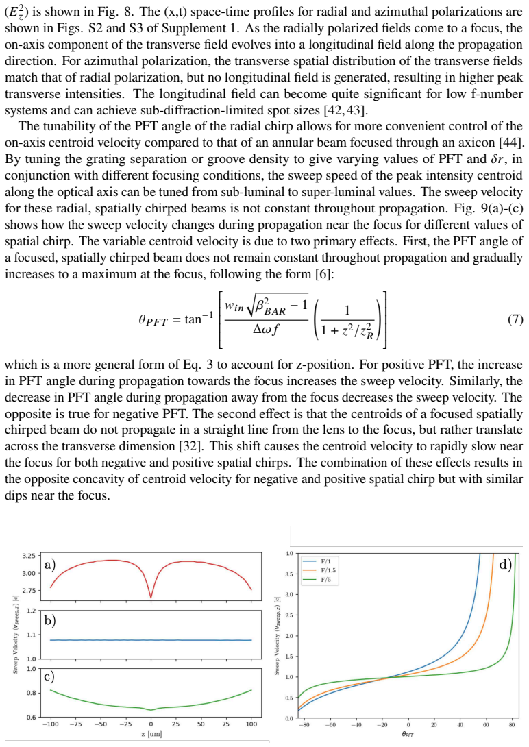
- Tunable sub- and super-luminal on-axis sweep speeds become a design parameter: choosing grating separation, groove density, and focusing $f$-number sets the focal-plane centroid velocity through Eq. (8).
- Radial chirp produces a symmetric conical pulse front, so non-reciprocal pulse-front-tilt-dependent effects that occur with 1D chirp should be symmetrized in laser-material interactions.
- Radial and azimuthal polarization states give focal volumes with enhanced or suppressed longitudinal field, offering control over sub-diffraction-limited spots and the field polarization at focus.
- Coherent arrays of four 1D chirped beams can reproduce the main focal properties of radial chirp using conventional high-damage-threshold gratings, with independent control of offset, chirp sign, orientation, and polarization; the demonstrated four-beam case reaches 77% of the ideal peak intensity.
- Independently controlling chirp strength and offset (rather than coupling them through a single grating pair) allows shaping of the focal cone angle, fringe visibility, and temporal focusing, including a pulse-front-tilt-matching regime with a $90^\circ$ apparent cone angle.
Reading between the lines
- A likely practical extension is optimizing the number of beams and the expansion ratio: the paper's single demonstration suggests a trade-off between peak intensity (better with fewer, larger beams) and azimuthal fidelity (better with more beams), and a systematic sweep over $\bar{\beta}$ and $\delta_r$ would map where the approximation holds.
- Because the scheme relies on coherent combining, alignment and phase-locking tolerances—piston, tip, and tilt errors between beam lines—are the likeliest failure mode in a real high-energy system; the paper does not quantify this sensitivity, so a tolerance study is a natural next check.
- Equation (8) gives a direct design recipe: one could choose an $f$-number and pulse-front-tilt angle to hit a specified centroid speed, enabling velocity-tunable laser-driven interactions without custom annular optics.
- The tunable symmetric pulse-front cone could also serve as a testbed for space-time wave packets, since independent control of $\bar{\beta}$ and $\delta_r$ spans nearly planar to strongly conical space-time topologies; the paper does not explore that regime.
Editorial analysis
A structured set of objections, weighed in public.
Referee Report
Summary. This manuscript studies focused radially chirped, axisymmetric spatially chirped beams. Using vectorial Rayleigh-Sommerfeld propagation, the authors characterize focal-plane (x,t) intensity patterns, fringe spacing, pulse-front tilt, on-axis centroid velocity, and the effect of linear, radial, and azimuthal polarization. They then propose approximating the radial chirp with coherent arrays of 1D spatially chirped beams, showing for one configuration that a four-beam array reaches 77% of the peak focal intensity of the ideal radial beam. The central claims are tunable superluminal/sub-luminal centroid velocity, symmetric pulse-front tilt, and the feasibility of multi-beam mimicry.
Significance. The paper provides a systematic simulation-based characterization of focused radially chirped beams, covering negative/positive chirp, polarization states, and centroid-velocity tuning. The use of physically motivated grating-generated fields and vectorial Rayleigh-Sommerfeld propagation is a strength, and the analytic trends for fringe spacing (Eq. 5) and pulse-duration scaling (Eq. 6) match cited prior results. The proposed multi-beam approximation, if validated, would offer a practical route to high-intensity radially chirped beams using conventional gratings. However, the current evidence for the approximation is limited to one configuration and one intensity plane, so the practical claim is not yet fully established.
major comments (3)
- [Sec. 3.1 and Fig. 10] The central practical conclusion stated in the Abstract and Sec. 4 — that arrays of 1D spatially chirped beams 'maintain all the properties' of radially chirped beams — is not supported by the evidence presented. The only comparison shown is a single configuration (β_BAR = 5, δr = 0.5 cm) and a single observable: the t = 0 focal-plane intensity. No comparison is shown for the on-axis centroid velocity of Eq. (8), the symmetric pulse-front tilt/conical structure during propagation, the transverse intensity modulations at other times or planes, or the vector polarization composition (E_z vs. E_x, E_y). Because the authors explicitly state that parameter exploration is outside the scope of this manuscript, the demonstrated case cannot justify the general claim. I recommend either adding these comparisons for a representative set of parameters or substantially qualifying the conclusion.
- [Sec. 3.1 and Fig. 10] The vector-polarization mimicry is not established. Fig. 10 uses four linearly polarized 1D chirped beams to approximate a radially polarized radially chirped beam, but four discrete linear polarization directions cannot reproduce a continuous radial polarization distribution. Consequently, the longitudinal field component, whose magnitude is a headline result for the ideal beam (Fig. 8), and the polarization-dependent focal structure will differ in a way that is not quantified. The claim that the approximation maintains 'polarization states' from the Abstract therefore needs either explicit demonstration or a clear qualification.
- [Sec. 3.1, Fig. 10(d-f)] The similarity between the multi-beam approximation and the radial beam is assessed only qualitatively. The intensities in Fig. 10(d-f) are normalized to the peak of the radial beam, and the text states that the twelve-beam case is 'more spatially similar' and that the four-beam case achieves 'higher peak intensities,' but no quantitative similarity metric (e.g., RMS difference, correlation, or mode overlap) is provided. This makes it difficult to judge whether the approximation is adequate for applications such as high-power focusing.
minor comments (4)
- [Sec. 2, Eq. (4)] The notation β_BAR is introduced but the typesetting in the manuscript is inconsistent; please ensure all symbols render correctly in the final version.
- [Sec. 3, Fig. 7(a)] The definition of Λ and the exact dependence on δr and β_BAR are not clear from the figure; please state the parameters used and define the plotted quantity explicitly.
- [Sec. 3, Eq. (8)] The derivation of Eq. (8) is not given; please either provide a derivation or a specific citation, and define the sign convention for positive/negative spatial chirp so that superluminal/sub-luminal velocities are unambiguous.
- [Sec. 2] There are typographical errors, e.g., 'the the' in Sec. 2 and an apparent '0° AOI' rendering issue; a careful proofread is needed.
Circularity Check
No material circularity: the paper's analytic formulas are cited from independent prior work and the simulations are self-contained; the only self-citation (Ref. 32) is not load-bearing.
full rationale
The paper's derivation chain is not circular. The input fields are constructed from the grating equation and standard spatially chirped-beam geometry (Section 2), then propagated with the vectorial Rayleigh-Sommerfeld convolution and Bluestein method, which are independent numerical techniques (Refs. 33-38). The analytic expressions for pulse-front-tilt angle (Eqs. 2-4), fringe spacing (Eq. 5), temporal focusing (Eq. 6), and z-dependent PFT angle (Eq. 7) are cited from prior external or independent sources (Refs. 4, 6, 41), not derived from the paper's own output. Equation 8 is presented as an analytic form for the on-axis centroid velocity and is compared with simulation in Fig. 9; nothing indicates it was fitted to those simulations. The multi-beam mimicry claim in Section 3.1 is a direct simulation comparison with equal energy partition and stated input parameters; the 48% and 77% peak-intensity values are emergent simulation results, not fitted parameters. The only self-citation is Ref. 32, used to justify grating-equation-derived chirp profiles and to explain centroid translation near focus; it is supporting context rather than the load-bearing step, and it does not by itself force any conclusion. The broader conclusion in Section 4 that the four-beam approximation 'maintains all the properties' is stronger than the single-parameter, single-observable test shown, but that is an evidence-conclusion mismatch, not circular reasoning. Under the stated rules, no circular step can be exhibited, so the circularity score is minimal.
Assumptions & free parameters
free parameters (4)
- Input beam radius w_in =
0.5 mm
- Spectral bandwidth Delta_omega =
100 nm FWHM at 800 nm
- Focusing and grating geometry (focal length f, groove density, grating separation) =
f = 5 cm; 500 or 700 lines/mm
- Aspect ratio beta_BAR and center-frequency offset delta_r =
beta_BAR = 2, 5, 10; delta_r = 1, 2, 3, 4 cm across figures
assumptions (5)
- domain assumption Vectorial Rayleigh-Sommerfeld propagation with Bluestein sampling accurately models non-paraxial focused few-cycle pulses.
- domain assumption The focusing optic is an ideal thin lens and the pulse is transform-limited after the lens.
- domain assumption Concentric ring gratings have uniform diffraction efficiency independent of polarization.
- domain assumption Analytic SSTF formulas for PFT and centroid velocity (Eqs. 4-8) remain valid for radially chirped, vectorially polarized pulses.
- domain assumption Coherent combination of N beams with matched orientation, delta_r, beta_BAR, and polarization reproduces the ideal radial chirp without phase or alignment errors.
Cite this review
Pith. "Pith review of Focused axisymmetric spatially chirped beams." pith.science (2026). https://pith.science/paper/BQNR2X64
@misc{pith2026250524817,
  author       = {Pith},
  title        = {Pith review of: Focused axisymmetric spatially chirped beams},
  year         = {2026},
  howpublished = {\url{https://pith.science/paper/BQNR2X64}},
  note         = {Machine review of arXiv:2505.24817}
}
read the original abstract
A characterization of the focused space-time structures of radially chirped beams is provided, detailing different tunable properties such as: variable on-axis centroid velocity, symmetric pulse front tilt, transverse intensity modulations, and polarization states. While the practical generation of ideal radially chirped beams and polarizations can be problematic, it is shown that the primary characteristics of these beams can be mimicked with simple arrays of axisymmetric, 1D spatially chirped beams.
Figures


Figures from the paper (7 more)



Reference graph
Works this paper leans on
-
[1]
Spatiotemporal sculpturing of light: a tutorial,
Q. Zhan, “Spatiotemporal sculpturing of light: a tutorial,” Adv. Opt. Photonics 16 (2024)
work page 2024
-
[2]
Optical chirped beam amplification and propagation,
C. P . J. Barty, “Optical chirped beam amplification and propagation,” U.S. patent 6,804,045B2 (12 Oct 2004)
work page 2004
-
[3]
Simultaneous spatial and temporal focusing for axial scanning,
M. E. Durst, G. Zhu, and C. Xu, “Simultaneous spatial and temporal focusing for axial scanning,” Opt. Express 14, 12243–12254 (2006)
work page 2006
-
[4]
Intuitive analysis of space-time focusing with double-ABCD calculation,
C. G. Durfee, M. Greco, E. Block, et al., “Intuitive analysis of space-time focusing with double-ABCD calculation,” Opt. Express 20, 14244–14259 (2012)
work page 2012
-
[5]
On the localization of the high-intensity region of simultaneous space-time foci,
E. Archer, B. Sun, R. Walczak, et al., “On the localization of the high-intensity region of simultaneous space-time foci,” Opt. Express 33 (2025)
work page 2025
-
[6]
A. M. Wilhelm, “Tilted snowplow electron acceleration with simultaneously spatially and temporally focused laser pulses,” Ph.d., Colorado School of Mines (2021)
work page 2021
-
[7]
A. M. Wilhelm and C. G. Durfee, “Tilted snowplow ponderomotive electron acceleration with spatio-temporally shaped ultrafast laser pulses,” Front. Phys. 7 (2019)
work page 2019
-
[8]
P . Hunt, A. Wilhelm, D. Adams, et al., “Ponderomotive snowplow electron acceleration with high energy tilted ultrafast laser pulses (preprint),” Res. Sq. (2024)
work page 2024
Show all 43 references
-
[9]
Scanningless depth-resolved microscopy,
D. Oron, E. Tal, and Y . Silberberg, “Scanningless depth-resolved microscopy,” Opt. Express 13, 1468–1476 (2005)
2005
-
[10]
Scanless two-photon excitation with temporal focusing,
E. Papagiakoumou, E. Ronzitti, and V . Emiliani, “Scanless two-photon excitation with temporal focusing,” Nat. Methods 17, 571–581 (2020)
2020
-
[11]
Spatio-temporally focused femtosecond laser pulses for nonreciprocal writing in optically transparent materials,
D. N. Vitek, E. Block, Y . Bellouard, et al., “Spatio-temporally focused femtosecond laser pulses for nonreciprocal writing in optically transparent materials,” Opt. Express 18, 24673–24678 (2010)
2010
-
[12]
Enhancing precision in fs-laser material processing by simultaneous spatial and temporal focusing,
R. Kammel, R. Ackermann, J. Thomas, et al., “Enhancing precision in fs-laser material processing by simultaneous spatial and temporal focusing,” Light. Sci. & Appl. 3, e169–e169 (2014)
2014
-
[13]
Direct writing with tilted-front femtosecond pulses,
A. Patel, Y . Svirko, C. Durfee, and P . G. Kazansky, “Direct writing with tilted-front femtosecond pulses,” Sci. Reports 7, 12928 (2017)
2017
-
[14]
Four-dimensional light shaping: manipulating ultrafast spatiotemporal foci in space and time,
B. Sun, P . S. Salter, C. Roider, et al., “Four-dimensional light shaping: manipulating ultrafast spatiotemporal foci in space and time,” Light. Sci. & Appl. 7, 17117–17117 (2018)
2018
-
[15]
Space-time wave packets localized in all dimensions,
M. Y essenov, J. Free, Z. Chen,et al., “Space-time wave packets localized in all dimensions,” Nat. Commun. 13, 4573 (2022)
2022
-
[16]
Spatio-temporal couplings in ultrashort laser pulses,
S. Akturk, X. Gu, P . Bowlan, and R. Trebino, “Spatio-temporal couplings in ultrashort laser pulses,” J. Opt. 12, 093001 (2010)
2010
-
[17]
T wo-dimensional spatiotemporal focusing of femtosecond pulses and its applications in microscopy,
Q. Song, A. Nakamura, K. Hirosawa, et al., “T wo-dimensional spatiotemporal focusing of femtosecond pulses and its applications in microscopy,” Rev. Sci. Instruments 86, 083701 (2015)
2015
-
[18]
Integrated single grating compressor for variable pulse front tilt in simultaneously spatially and temporally focused systems,
E. Block, J. Thomas, C. Durfee, and J. Squier, “Integrated single grating compressor for variable pulse front tilt in simultaneously spatially and temporally focused systems,” Opt. Lett. 39, 6915–6918 (2014)
2014
-
[19]
Independent control of aspect ratios in the axial and lateral cross sections of a focal spot for three-dimensional femtosecond laser micromachining,
F. He, Y . Cheng, J. Lin, et al., “Independent control of aspect ratios in the axial and lateral cross sections of a focal spot for three-dimensional femtosecond laser micromachining,” New J. Phys. 13 (2011)
2011
-
[20]
Analysis of pulse front tilt in simultaneous spatial and temporal focusing,
S. Zhang, D. Asoubar, R. Kammel, et al., “Analysis of pulse front tilt in simultaneous spatial and temporal focusing,” J. Opt. Soc. Am. A 31, 2437–2446 (2014)
2014
-
[21]
Circular and spiral diffraction gratings,
J. Dyson, “Circular and spiral diffraction gratings,” Proc. Royal Soc. London. Ser. A. Math. Phys. Sci. 248, 93–106 (1958)
1958
-
[22]
Concentric ring metal grating for generating radially polarized light,
Z. Ghadyani, I. Vartiainen, I. Harder, et al., “Concentric ring metal grating for generating radially polarized light,” Appl. Opt. 50, 2451–2457 (2011)
2011
-
[23]
Nonlinear space-time focusing and filamentation of annular femtosecond pulses in dielectrics,
T. E. Lanier and J. R. Gulley, “Nonlinear space-time focusing and filamentation of annular femtosecond pulses in dielectrics,” J. Opt. Soc. Am. B 33, 292–301 (2016)
2016
-
[24]
Concentric-ring-grating-induced strong terahertz near-field enhancement on a micro-tip,
X. Zhou, X. Guo, A. Shkurinov, and Y . Zhu, “Concentric-ring-grating-induced strong terahertz near-field enhancement on a micro-tip,” J. Opt. 21, 105005 (2019)
2019
-
[25]
Space–time focusing of bessel-like pulses,
M. Clerici, D. Faccio, E. Rubino, et al., “Space–time focusing of bessel-like pulses,” Opt. Lett. 35, 3267–3269 (2010)
2010
-
[26]
Spatiotemporal control of laser intensity,
D. H. Froula, D. T urnbull, A. S. Davies, et al., “Spatiotemporal control of laser intensity,” Nat. Photonics 12, 262–265 (2018)
2018
-
[27]
Use of spatiotemporal couplings and an axiparabola to control the velocity of peak intensity,
A. Liberman, R. Lahaye, S. Smartsev, et al., “Use of spatiotemporal couplings and an axiparabola to control the velocity of peak intensity,” Opt Lett 49, 814–817 (2024)
2024
-
[28]
Spatiotemporal optical injection,
E. Archer, “Spatiotemporal optical injection,” Thesis, University of Oxford (2024). 29. S. Jolly and M. Porras, “Analytical fields of an ultrashort, radially polarized laser with spatial chirp,” J. Opt. Soc. Am. B (2024)
2024
-
[30]
Realization of free-space long-distance self-healing bessel beams,
C. Vetter, R. Steinkopf, K. Bergner, et al., “Realization of free-space long-distance self-healing bessel beams,” Laser & Photonics Rev. 13 (2019)
2019
-
[31]
Characteristic analysis of a refractive axicon system for optical trepanning,
W. P . Latham, “Characteristic analysis of a refractive axicon system for optical trepanning,” Opt. Eng. 45 (2006)
2006
-
[32]
Pulse front distortions in focused spatially chirped beams,
E. C. Nelson, K. D. Chesnut, T. Reutershan, et al., “Pulse front distortions in focused spatially chirped beams,” Opt. Continuum 3, 1051–1060 (2024)
2024
-
[33]
Optics. lectures on theoretical physics, vol. iv,
A. Sommerfeld and K. W. Meissner, “Optics. lectures on theoretical physics, vol. iv,” Am. J. Phys. 23, 477–478 (1955)
1955
-
[34]
Born and E
M. Born and E. Wolf, Principles of Optics: Electromagnetic Theory of Propagation, Interference and Diffraction of Light (Cambridge University Press, Cambridge, 1999), 7th ed
1999
-
[35]
J. W. Goodman, Introduction to Fourier Optics (McGraw-Hill Book Company, Inc., 1988)
1988
-
[36]
D. G. Voelz, Computational Fourier Optics: A MATLAB Tutorial (SPIE, 2011)
2011
-
[37]
Efficient full-path optical calculation of scalar and vector diffraction using the bluestein method,
Y . Hu, Z. Wang, X. Wang, et al., “Efficient full-path optical calculation of scalar and vector diffraction using the bluestein method,” Light Sci Appl 9, 119 (2020)
2020
-
[38]
A linear filtering approach to the computation of discrete fourier transform,
L. Bluestein, “A linear filtering approach to the computation of discrete fourier transform,” IEEE Trans. on Audio Electroacoustics 18, 451–455 (1970)
1970
-
[39]
SSTF-symmetric,
E. C. Nelson, “SSTF-symmetric,” figshare (2025) , https://doi.org/10.6084/m9.figshare. 29175305
2025 doi
-
[40]
Application of space-time structured light to controlled high-intensity laser matter interactions in point and line target geometries,
A. K. Meier, “Application of space-time structured light to controlled high-intensity laser matter interactions in point and line target geometries,” Thesis, Colorado School of Mines (2015)
2015
-
[41]
Interference patterns of two focused gaussian beams in an LDA measuring volume,
E. Li, K. Tieu, and M. Mackenzie, “Interference patterns of two focused gaussian beams in an LDA measuring volume,” Opt. Lasers Eng. 27, 395–407 (1997)
1997
-
[42]
Sub-wavelength focal spot with long depth of focus generated by radially polarized, narrow-width annular beam,
K. Kitamura, K. Sakai, and S. Noda, “Sub-wavelength focal spot with long depth of focus generated by radially polarized, narrow-width annular beam,” Opt. Express 18, 4518–4525 (2010)
2010
-
[43]
Minimized spot of annular radially polarized focusing beam,
L. Y ang, X. Xie, S. Wang, and J. Zhou, “Minimized spot of annular radially polarized focusing beam,” Opt. Lett. 38, 1331–1333 (2013)
2013
-
[44]
Couairon, D
A. Couairon, D. Faccio, and P . Di Trapani, Conical Waves, Filaments and Nonlinear Filamentation Optics (Aracne, 2007). Focused axisymmetric spatially chirped beams: supplemental document Fig. S1. (x,t) representations of the total intensity ( E2x + E2y + E2z ) of the focus ( ...
2007
Reviewed August 7, 2026 · model on record in the stance chip above.
Discussion (0). Sign in to comment.