REVIEW 2 major objections 3 minor 24 references
Optical polarimetry based on geometric phase measurements: unitary Jones matrices
T0 review · 2 major / 3 minor · reviewed 2026-08-14 · deepseek-v4-flash
Pith's one-line read For homogeneous lossless polarization elements, geometric-phase measurements alone determine both the element's Jones matrix and the beam's Stokes vector.
desk verdict Core inversion idea is sound and the theory is clean, but Sec. 4 carries a sign error that flips the recovered s3, and the paper misattributes the resulting discrepancy to waveplate quality. read the letter →
The pith
A machine-rendered reading of the paper's core claim, the machinery that carries it, and where it could break.
The reading
What carries the argument
The central object is the tangent identity $\tan(\Phi_G) = (Q\cdot A)\tan(\delta)$ for homogeneous unitary Jones matrices, which converts a geometric-phase measurement into a linear inverse problem. The identity follows from the total-phase formula $\Phi = \arg\{\mu_1+\mu_2+(\mu_1-\mu_2)Q\cdot A\}$ together with the sign-reversal property $\Phi_G(A_\perp) = -\Phi_G(A)$ for orthogonal input states, which is what lets the experimental fringe shift isolate $2\Phi_G$. Equation (5) inverts the $3\times 3$ matrix of input Stokes vectors to obtain $\bar Q = \tan(\delta)Q$, and Eq. (27) performs the conjugate inversion with three calibrated elements to obtain the unknown Stokes vector $A$. The experimental carrier is a Mach-Zehnder interferometer that produces two interference patterns with phases $\Phi_D+\Phi_G$ and $\Phi_D-\Phi_G$; multiplying the Fourier transforms of the two patterns and evaluating at the fringe frequency extracts the geometric phase independently of the dynamic phase.
What would settle it
Take a weakly absorbing retarder with known but unequal eigenvalue magnitudes $|\mu_1|\neq|\mu_2|$, apply the three-measurement inversion, and compare the recovered eigenpolarization and $\delta$ with an independent ellipsometric measurement; Eq. (4) predicts a straight line through the origin in a plot of $\tan(\Phi_G)$ versus $Q\cdot A$, so any systematic curvature or offset as absorption is increased falsifies the central relation.
Extended reading notes
Core claim
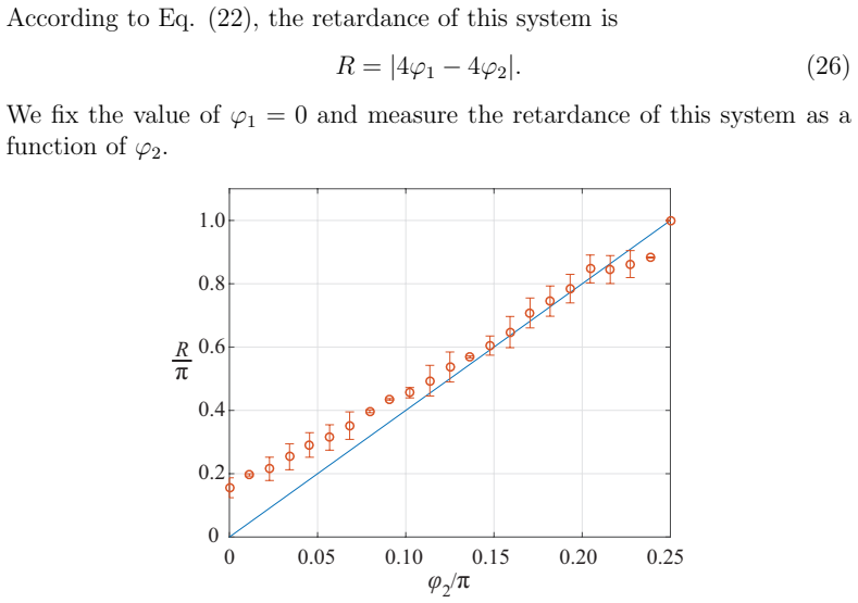
The paper's central claim is that the geometric phase is a complete polarimetric observable for a homogeneous, unitary Jones matrix. For such a system, with eigenpolarizations represented by opposite Stokes vectors $\pm Q$ and eigenvalues $\mu_{1,2}=e^{\pm i\delta}$, the geometric phase acquired by input state $A$ collapses to the tangent identity $\tan(\Phi_G) = (Q\cdot A)\tan(\delta)$, a direct corollary of the total-phase formula $\Phi = \arg\{\mu_1+\mu_2+(\mu_1-\mu_2)Q\cdot A\}$. Because this relation is linear in the components of $Q$, three measurements of $\Phi_G$ for three known input Stokes vectors fix $Q$ and $\delta$ by a $3\times 3$ inversion; conversely, with three calibrated elements of known eigenpolarization, the same inversion returns the unknown Stokes vector $A$. The experimental readout is a Mach-Zehnder interferometer in which two orthogonal input states pass through the sample and the geometric phase is read from the relative displacement of their interference fringes using a Fourier-domain product of the two interferograms. The measured retardance of a quarter-half-quarter wave-plate system follows the predicted linear law, and the reconstructed Stokes parameters of a beam behind a rotating quarter-wave plate trace the expected curves, with the third parameter deviating after $\pi/2$ because of wave-plate quality.
Load-bearing premise
The retrieval rests on the imported total-phase formula for a homogeneous Jones matrix and its corollary that orthogonal input states acquire opposite geometric phases; if the sample has even slight absorption or inhomogeneity, the fringe shift no longer isolates $\Phi_G$ and the recovered $Q$ and $\delta$ are wrong.
Editorial extensions
If this is right
- The full Jones matrix of any homogeneous, non-absorbing polarization element can be reconstructed from exactly three geometric-phase measurements, with no intensity projections.
- The Stokes parameters of an unknown beam can be obtained by placing three calibrated wave-plate systems in the interferometer and solving Eq. (27), so polarimetry can be performed without rotating analyzers.
- Because the relation is linear in $Q$, any increase in the number of input states beyond three could be used as a consistency check or least-squares refinement of the recovered eigenpolarization.
- The inversion formulas are independent of how $\Phi_G$ is measured, so a non-interferometric geometric-phase method would make the technique applicable in compact settings.
- The approach is limited to homogeneous, unitary Jones matrices; inhomogeneous matrices break the sign-reversal property and fall outside the method, as the paper states.
Reading between the lines
- An untested consequence of the linear inversion is noise sensitivity: the error in $Q$ and $\delta$ should scale with the condition number of the input-Stokes matrix, so triads of nearly coplanar input states would amplify measurement noise; this is testable by comparing retrievals from well-spread and nearly coplanar triads.
- The same algebra maps directly onto two-level quantum systems via the SU(2) correspondence the paper notes, so a qubit's state or its unitary evolution parameters could, in principle, be read from three geometric-phase-like measurements of a two-path interferometer.
- Because the sign-reversal property is essential, a quick diagnostic for sample homogeneity would be to check whether the measured $\Phi_G$ for input state $A$ is exactly opposite to that for $A_\perp$; a nonzero deviation flags inhomogeneity before any inversion is trusted.
- The paper's third Stokes-parameter discrepancy after $\pi/2$, attributed to wave-plate quality, suggests a practical test: replacing the half-wave plates with higher-grade retarders should make $s_3$ follow the theoretical curve, and the residual deviation would quantify the hardware-limited accuracy of the technique.
Signed reviews
Editorial analysis
A structured set of objections, weighed in public.
Referee Report
Summary. The manuscript proposes a polarimetry technique based on measuring the Pancharatnam-Berry geometric phase instead of intensity projections. For a homogeneous unitary Jones matrix J with eigenpolarization Stokes vector Q and eigenvalue phase delta, the authors use an earlier total-phase formula to write tan(Phi_G) = (Q dot A) tan(delta) (Eq. 4). They then show that three geometric-phase measurements with input Stokes states H, D, and R determine Q and delta through a linear inversion (Eq. 5), and that three calibrated unitary systems determine an unknown Stokes vector A (Eq. 27). The paper reports an interferometric Mach-Zehnder experiment: the retardance of a QWP-HWP-QWP system as a function of HWP angle (Fig. 2) and the Stokes parameters of a beam after a rotating quarter-wave plate (Fig. 3).
Significance. The proposed method is an interesting alternative to intensity-projection polarimetry, and the inversion algebra is clean and parameter-free: no fitted constants enter Eq. (4) or Eq. (27). The paper also acknowledges the practical limitation that interferometry is required and states that the approach extends to SU(2) two-level systems. The experimental support is partial: Fig. 2 validates only the retardance, not the eigenpolarizations, and the Stokes calibration in Section 4 contains a sign error that directly affects the measured s3. Because the central inversion is mathematically sound but the experimental validation and calibration need correction, the result is promising but not yet fully supported.
major comments (2)
- [Sec. 4, item 3 and Eq. (28)] Using Eq. (7) and the stated component order ('first half-wave plate at 90 degrees and second at 22.5 degrees'), the composite system is J = HWP(pi/8) HWP(pi/2) = (sqrt(2)/2) [[1, -1], [1, 1]]. Its eigenvector for the eigenvalue exp(+i pi/4) is [1; -i]/sqrt(2), whose normalized Stokes vector under S3 = 2 Im(Ex* Ey) is [0; 0; -1], not [0; 0; 1]. Consequently, the third row of the calibration matrix in Eq. (27) has the wrong sign, and Eq. (28) should read A3 = -tan(Phi_G)_3. This sign flip is the natural explanation for the s3 discrepancy in Fig. 3; the attribution to the quality of the half-wave plates is not supported once the sign error is present. If the authors intended the opposite product order, the text and Eq. (7) need to be reconciled with the standard column-vector convention.
- [Sec. 3.3, Fig. 2] Section 3 claims that Eq. (5) determines the eigenpolarizations Q and -Q in addition to the retardance, but Fig. 2 plots only the retardance R against the theoretical line. No measured Q (or measured delta) is compared with the theoretical eigenpolarizations of Eqs. (23)-(24), so the central inversion in Eq. (5) is not directly validated. Reporting the recovered Q for at least one set of angles, or clearly stating that only the retardance is being validated, is necessary to support the eigenpolarization claim and to build confidence in the calibration used in Section 4.
minor comments (3)
- [Sec. 3.2, Eq. (21)] The phase extracted from the product f1* f2 is -2 Phi_G for the peak at +k0 and +2 Phi_G for the peak at -k0; the text should state explicitly which spectral peak is used so the sign of Phi_G is unambiguous.
- [Sec. 4, Fig. 3] No error bars are shown in Fig. 3, and the statement that the error bars are negligible because of mechanical stability is not quantified; please provide at least the standard deviation of repeated interferogram analyses.
- [Sec. 3, Eq. (4)] The convention for the Stokes parameters should be stated explicitly; Eq. (8) gives a formula for one input state, but the definitions of S2 and S3 in terms of Ex and Ey are not written out, which is important for reproducing the sign conventions used in the calibration.
Circularity Check
No circularity by construction: Eq. (4) is imported from prior published work of the same group, but it is parameter-free and independently validated here, so the self-citation does not force the measured results.
full rationale
The paper's central relation Eq. (4), tan(Phi_G) = Q·A tan(delta), is derived from Eq. (1), which is cited to Refs. [12,18,19]. Refs. [12] and [19] involve the present authors, so there is a self-citation. However, Eq. (1) is a published, parameter-free formula with explicit assumptions (homogeneous, non-absorbing Jones matrices, |mu1|=|mu2|=1) and is not re-fitted to the data in this paper. The inversion in Eq. (5) takes three measured geometric-phase tangent values and algebraically solves for Q and delta; no fitted constant is renamed as a prediction. The inversion in Eq. (27) similarly solves for the unknown Stokes vector A from three measured tangent values using independently calibrated wave-plate systems. The experimental validation in Fig. 2 checks the geometric-phase-derived retardance against the independent theoretical prediction Eq. (26) for a known QWP-HWP-QWP stack, which is an external falsifiability test rather than a constructional tautology. The Sec. 4 calibration for the third system, HWP(pi/8)HWP(pi/2), has a sign error: using the paper's own Jones convention, the eigenpolarization paired with eigenvalue e^{+i pi/4} is [0;0;-1], not [0;0;1], so Eq. (28)'s third row should be negated and the recovered A3 carries the wrong sign. This is a correctness defect in the calibration, not a circularity: it makes the calibration matrix incorrect, but it does not make the output equal to the input by definition. Therefore no circular step is exhibited. The score reflects only the paper's admitted reliance on a self-cited starting formula for the geometric-phase relation; that reliance is load-bearing but is supported by prior independent publication and by the in-paper external benchmark, so the score is low.
Assumptions & free parameters
assumptions (5)
- domain assumption The total phase difference between input and output of a homogeneous Jones matrix is Φ = arg{μ1+μ2+(μ1−μ2)Q·A} (Eq. 1), as derived in Refs. [12,18,19].
- domain assumption The sample is homogeneous and unitary, so its eigenpolarizations are orthogonal and |μ1| = |μ2| = 1.
- domain assumption The interferometer fringe phase is exactly Φ_D ± Φ_G with no residual phase offset between the two arms.
- standard math The QWP and HWP Jones matrices in Eqs. (6)-(7) describe the wave plates.
- domain assumption The three basis input states H, D, and R are generated exactly.
Cite this review
Pith. "Pith review of Optical polarimetry based on geometric phase measurements: unitary Jones matrices." pith.science (2026). https://pith.science/paper/CHKST5GJ
@misc{pith2026190803829,
  author       = {Pith},
  title        = {Pith review of: Optical polarimetry based on geometric phase measurements: unitary Jones matrices},
  year         = {2026},
  howpublished = {\url{https://pith.science/paper/CHKST5GJ}},
  note         = {Machine review of arXiv:1908.03829}
}
read the original abstract
We demonstrate a polarimetry technique based on geometric phase measurements. The technique can be used to obtain either the polarization state of a light beam or the properties of a polarizing optical system. On the one hand, we apply our method to determine the properties of homogeneous and unitary Jones matrices. On the other hand, we provide the recipe to measure the Stokes parameters of a light beam without requiring intensity projections.
Figures


Reference graph
Works this paper leans on
-
[19]
Stokes and jones ma - trix polarimetry based on geometric phase measurements
Israel Melendez-Montoya, Diana Laura Gonzalez-Hernandez , Alejandra De-Luna-Pamanes, and Dorilian Lopez-Mago. Stokes and jones ma - trix polarimetry based on geometric phase measurements. Proc. SPIE, 10749:107491A, 2018
work page 2018
-
[1]
M. V. Berry. Quantal Phase Factors Accompanying Adiabatic Ch anges. Proc. R. Soc. A Math. Phys. Eng. Sci. , 392:45–57, 1984. 12
work page 1984
-
[2]
M.V. Berry. The Adiabatic Phase and Pancharatnam’s Phase for P o- larized Light. J. Mod. Opt. , 34:1401–1407, 1987
work page 1987
-
[3]
Halina Rubinsztein-Dunlop, Andrew Forbes, M V Berry, M R Dennis, David L Andrews, Masud Mansuripur, Cornelia Denz, Christina Alp- mann, Peter Banzer, Thomas Bauer, Ebrahim Karimi, Lorenzo Mar- rucci, Miles Padgett, Monika Ritsch-Marte, Natalia M Litchinitser, Nicholas P Bigelow, C Rosales-Guzm´ an, A Belmonte, J P Torres, Tyler W Neely, Mark Baker, Reuven...
work page 2017
-
[4]
L. Marrucci, C. Manzo, and D. Paparo. Pancharatnam-Berry p hase optical elements for wave front shaping in the visible domain: Switcha ble helical mode generation. Appl. Phys. Lett. , 88:221102, 2006
work page 2006
-
[5]
Spin-dependent manipulating of vector beams by tailoring polarization
Junxiao Zhou, Wenshuai Zhang, Yachao Liu, Yougang Ke, Yuany uan Liu, Hailu Luo, and Shuangchun Wen. Spin-dependent manipulating of vector beams by tailoring polarization. Sci. Rep. , 6:34276, 2016
work page 2016
-
[6]
Ruisi Wang, Shanshan He, Shizhen Chen, Jin Zhang, Weixing Shu, H ailu Luo, and Shuangchun Wen. Electrically driven generation of arbitra ry vector vortex beams on the hybrid-order Poincar´ e sphere.Optics Letters, 43:3570, 2018
work page 2018
-
[7]
Jisha , Bruno Piccirillo, Enrico Santamato, Gaetano Assanto, and Lorenzo Marru cci
Sergei Slussarenko, Alessandro Alberucci, Chandroth P. Jisha , Bruno Piccirillo, Enrico Santamato, Gaetano Assanto, and Lorenzo Marru cci. Guiding light via geometric phases. Nat. Photonics , 10:571–575, 2016
work page 2016
Show all 24 references
-
[8]
A Geometric-phase Interferom eter
P Hariharan and Maitreyee Roy. A Geometric-phase Interferom eter. J. Mod. Opt. , 39:1811–1815, 1992
1992
-
[9]
Loredo, O
J. Loredo, O. Ort ´ ız, R. Weing¨ artner, and F. De Zela. Measure ment of Pancharatnam’s phase by robust interferometric and polarimetric meth- ods. Phys. Rev. A , 80:1–9, 2009
2009
-
[10]
Kobayashi, S
H. Kobayashi, S. Tamate, T. Nakanishi, K. Sugiyama, and M. Kita no. Direct observation of geometric phases using a three-pinhole inter ferom- eter. Phys. Rev. A , 81:3–6, 2010. 13
2010
-
[11]
The Pancharatnam-Berry phase for non-cyclic polarization chang es
Thomas van Dijk, Hugo F Schouten, Wim Ubachs, and Taco D Visse r. The Pancharatnam-Berry phase for non-cyclic polarization chang es. Opt. Express , 18:10796–804, 2010
2010
-
[12]
Hern andez- Aranda, and Julio C
Dorilian Lopez-Mago, Arturo Canales-Benavides, Raul I. Hern andez- Aranda, and Julio C. Guti´ errez-Vega. Geometric phase morpholo gy of Jones matrices. Opt. Lett., 42:2667, 2017
2017
-
[13]
Kwiat and Raymond Y
Paul G. Kwiat and Raymond Y. Chiao. Observation of a nonclassic al Berrys phase for the photon. Phys. Rev. Lett. , 66:588–591, 1991
1991
-
[14]
E igen- analysis of dichroic, birefringent, and degenerate polarization elem ents: a Jones-calculus study
Sergey N Savenkov, Oleksiy I Sydoruk, and Ranjan S Muttiah. E igen- analysis of dichroic, birefringent, and degenerate polarization elem ents: a Jones-calculus study. Appl. Opt. , 46:6700, 2007
2007
-
[15]
Shih-Yau Lu and Russell A. Chipman. Homogeneous and inhomoge - neous Jones matrices. J. Opt. Soc. Am. A , 11:766, 1994
1994
-
[16]
Goldstein
Dennis H. Goldstein. Polarized Light . CRC Press, 2010
2010
-
[17]
E. Collett. Field Guide to Polarization . Field Guide Series. Society of Photo Optical, 2005
2005
-
[18]
Pancharatnam-Berry phase of opt ical systems
Julio C Guti´ errez-Vega. Pancharatnam-Berry phase of opt ical systems. Opt. Lett., 36:1143–5, 2011
2011
-
[20]
Luis Jos´ e Salazar-Serrano, Alejandra Valencia, and Juan P. Torres. Tun- able beam displacer. Review of Scientific Instruments , 86:033109, 2015
2015
-
[21]
Measurement of Geometric Phase for Mixe d States Using Single Photon Interferometry
Marie Ericsson, Daryl Achilles, Julio Barreiro, David Branning, Nic holas Peters, and Paul Kwiat. Measurement of Geometric Phase for Mixe d States Using Single Photon Interferometry. Phys. Rev. Lett. , 94:1–4, 2005
2005
-
[22]
Larry Pezzaniti and Russell A
J. Larry Pezzaniti and Russell A. Chipman. Angular dependenc e of polarizing beam-splitter cubes. Appl. Opt. , 33:1916–1929, 1994. 14
1916
-
[23]
Gonzalez, Richard E
Rafael C. Gonzalez, Richard E. Woods, and Steven L. Eddins. Digital Image Processing Using MATLAB . Prentice-Hall, Inc., 2003
2003
-
[24]
Malhotra, R
T. Malhotra, R. Guti´ errez-Cuevas, J. Hassett, M. R. Denn is, A. N. Vamivakas, and M. A. Alonso. Measuring Geometric Phase without Interferometry. Physical Review Letters , 120:1–5, 2018. 15
2018
Reviewed August 14, 2026 · model on record in the stance chip above.
Discussion (0). Continue with ORCID to comment.