REVIEW 3 major objections 5 minor 15 references
ESPARGOS: An Ultra Low-Cost, Realtime-Capable Multi-Antenna WiFi Channel Sounder
T0 review · 3 major / 5 minor · reviewed 2026-08-07 · deepseek-v4-flash
Pith's one-line read Eight low-cost WiFi chips can be made into one phase-coherent channel sounder.
desk verdict A promising low-cost multi-antenna WiFi channel sounder whose phase-coherence claim still needs measured residual-error numbers. read the letter →
The pith
A machine-rendered reading of the paper's core claim, the machinery that carries it, and where it could break.
The reading
What carries the argument
The central mechanism is the two-stage synchronization and calibration chain: a shared 40 MHz reference clock makes all eight ESP32 receivers frequency-locked, and a WiFi phase reference signal, switched in place of the antenna, lets each receiver measure its own PLL and analog phase offset. The calibrated channel formula $\hat{h}_{\mathrm{CAL},m} = \hat{h}_{\mathrm{OTA},m}/\hat{h}_{\mathrm{REF},m} \, e^{-j\varphi_{\mathrm{path},m}}$ then removes both the unknown chip-specific phase and the known, constant phase shifts of the on-board distribution network, leaving only the true over-the-air channel phase. On the signal-processing side, the paper uses a sample covariance matrix built from measurements that may miss individual antennas, solved by a least-squares eigenvector estimate of the channel vector, so that one lost frame does not ruin the whole array estimate.
What would settle it
Place a transmitter at a precisely known angle in a line-of-sight environment, run the full phase and power calibration, and compute the MUSIC angular estimate: if the residual phase error is too large, the estimated angle will deviate well beyond the array's nominal resolution. A second check is to log the calibrated inter-antenna phase differences over several hours and across a temperature sweep, since the layout-determined offsets $\varphi_{\mathrm{path},m}$ are claimed to be constant.
Extended reading notes
Core claim
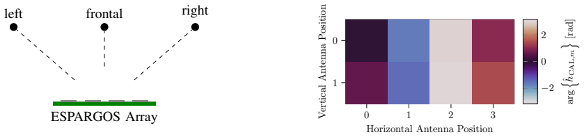
ESPARGOS establishes that a low-cost, coherent many-antenna WiFi receiver can be built from eight ESP32 microcontrollers on one four-layer FR4 board, without custom radio hardware. Frequency synchronization comes from a daisy-chained 40 MHz reference oscillator, and phase coherence comes from an additional WiFi-based phase reference signal fed to every receiver through a resistive divider and microstrip distribution network. Each receiver estimates the channel from the LLTF/HTLTF fields of passively sniffed WiFi frames, and the per-antenna calibrated channel coefficient is computed as $\hat{h}_{\mathrm{CAL},m} = \hat{h}_{\mathrm{OTA},m} / \hat{h}_{\mathrm{REF},m} \cdot e^{-j\varphi_{\mathrm{path},m}}$, where $\hat{h}_{\mathrm{REF},m}$ captures the ESP32 PLL and analog phase offset and $\varphi_{\mathrm{path},m}$ is the known, layout-determined phase delay of the reference distribution network. A principal-eigenvector estimator of the channel vector from the sample covariance matrix handles incomplete CSI when individual receivers miss frames. The paper's experimental evidence is a qualitative phase-stability test and a three-position angle-of-arrival test in which calibrated phases and MUSIC spectra separate left, frontal, and right transmitter locations.
Load-bearing premise
The entire scheme works only if the residual phase error left after the WiFi-reference calibration is small enough for coherent processing, and the paper does not report a measured residual error, uncertainty, or drift over temperature and time.
Editorial extensions
If this is right
- A research group or hobbyist can obtain 8-antenna, 20 MHz WiFi CSI from a single inexpensive board rather than a rack of software-defined radios.
- Because the phase reference signal removes PLL and analog hardware offsets, the calibrated phase vector should remain usable across chip resets and WiFi channel changes.
- Multiple ESPARGOS boards can be combined into a larger phase-coherent array by feeding the same 40 MHz clock and reference signal over one coaxial cable, using high-pass/low-pass filtering to separate them on the board.
- The covariance-based estimator tolerates missing frames from individual antennas, so real-world packet loss does not force a full retransmission or discard of the measurement interval.
- If the calibrated phases are as stable as the qualitative experiments suggest, the board becomes a usable platform for angle-of-arrival estimation and for prototyping joint communications and sensing algorithms.
Reading between the lines
- Editorial inference: the same clock-plus-WiFi-reference calibration architecture could be applied to any multi-chip WiFi receiver built from off-the-shelf parts, making this a general template for low-cost coherent arrays rather than a one-off device.
- Editorial inference: if the residual phase error proves to be small and stable, the eight-antenna board should support not just angle-of-arrival but also passive localization and channel charting, applications the paper names as future work but does not test.
- Editorial inference: a direct quantitative check of the calibration, such as comparing ESPARGOS phase measurements against a calibrated conducted reference or a precisely known transmitter angle, would turn the qualitative three-location demonstration into a measurable accuracy statement.
- Editorial inference: because the phase reference is itself a WiFi frame, the same calibration approach could in principle be extended to wider bandwidths or other ISM bands supported by commodity WiFi chips, though the paper only demonstrates 20 MHz operation.
Editorial analysis
A structured set of objections, weighed in public.
Referee Report
Summary. The paper presents ESPARGOS, an eight-antenna WiFi channel sounder built from commodity ESP32 microcontrollers on a single four-layer FR4 board, synchronized by a shared 40 MHz reference clock and calibrated by a WiFi-based phase reference signal distributed through an RF switch network. The authors derive a covariance-based channel estimator intended to handle missing per-antenna frame receptions, describe a phase and power calibration procedure, and report two qualitative experiments: a long-term phase-stability test and a MUSIC-based angle discrimination test for three transmitter positions. The hardware concept is low-cost and realtime-capable in principle, and the paper is clearly written with a useful system description.
Significance. If the phase-coherence claim is quantitatively confirmed, ESPARGOS would be a genuinely valuable tool for JCaS prototyping, channel charting, and education, making multi-antenna WiFi channel sounding accessible to groups that cannot afford SDR-based sounders. The design choice to share a reference clock and inject a known WiFi-based phase reference is practical and the calibration concept is sound. The paper also offers a transparent statistical estimator that is robust to missing CSI frames. However, the central claim of phase-coherent operation is currently supported only by qualitative experiments, so the significance is conditional on additional quantitative characterization.
major comments (3)
- [III-A, Eq. (4)] The channel estimator in Eq. (4) requires knowledge of the noise variance σ², but the paper never explains how σ² is obtained. The eigenvector direction is unaffected by σ², but the amplitude scaling factor sqrt(λ − σ²) enters every channel estimate and therefore propagates into the power calibration of Section III-B, where h_OTA,m and h_REF,m are divided. Please specify a concrete method for estimating σ² (e.g., from noise-only subcarriers or from the smallest eigenvalue of Ĉ) or explicitly state that σ² is treated as negligible and justify that for the reported measurements.
- [III-B and Fig. 3] The calibration equation h_CAL,m = h_OTA,m / h_REF,m · e^{−jφ_path,m} does not account for the differential phase introduced by the RF switch between its antenna port and its reference port, nor is such a term included in φ_path,m as defined. If the two switch paths have different insertion phases, that per-antenna constant phase appears in h_OTA but not in h_REF and is not removed by the division, leaving an unknown per-antenna phase offset that directly affects the phase-coherence claim. The paper should either state that the switch is designed to have identical phase on both paths, report a measurement of this differential phase, or add it to the calibration model.
- [IV] No quantitative validation of phase coherence is provided. Fig. 6 shows that uncalibrated phase differences remain stable in a static environment, which supports frequency synchronization but not the correctness of the absolute phase calibration; Fig. 9 shows MUSIC pseudo-spectra for three coarsely separated transmitter directions without ground-truth angles or error statistics. The conclusion explicitly states that quantitative performance testing remains future work, which is honest but leaves the central claim of a 'coherent' sounder unverified. Please add at least one of: measured residual phase errors after calibration with uncertainties, a comparison of estimated AoA against known transmitter angles, or a quantified phase-drift measurement over time and temperature.
minor comments (5)
- [II-B] The statement that phase offsets are 'determined by the geometry of the distribution network' would be easier to verify if the paper reported the values of φ_path,m or pointed to a design file where they can be computed; the current text leaves them as an unspecified constant.
- [III-A] The notation is confusing because T is used both for the total number of samples in Eq. (1) and for the set of time indices T_ij in the incomplete-CSI covariance estimator; please use distinct symbols to avoid ambiguity.
- [IV-A] Fig. 6 would be more informative with the sampling rate and the length of the moving average stated, and with the variance of the phase differences quantified in the static intervals rather than only shown qualitatively.
- [IV-B] The MUSIC pseudo-spectra in Fig. 9 should be labeled with the actual transmitter angles (or state that they are unknown), so the reader can judge the angular resolution; the y-axis is in dB but the reference value is not defined.
- [IV-B] There is a typo in 'AoA estimattation algorithms'; the word should be 'estimation'.
Circularity Check
No significant circularity: the calibration uses an independent injected reference signal, the estimator is derived from a stated statistical model, and the validation gap is a matter of experimental evidence, not of definitions.
full rationale
The paper's derivation chain is self-contained. The CSI covariance estimator in Section III-A is derived from a stated measurement model (r = h e^{jφ} + n) with additive i.i.d. noise, and the principal-eigenvector solution follows mathematically from the least-squares objective; no fitted constant is renamed as a prediction. The phase calibration formula h_CAL,m = h_OTA,m / h_REF,m * e^{-jφ_path,m} uses an independently injected WiFi reference signal whose channel estimate h_REF is obtained by the same estimator on a physically separate path, and φ_path,m is asserted to be a layout-determined constant rather than fit to the over-the-air data. The AoA experiment is checked against three known external transmitter locations and a standard MUSIC pseudo-spectrum, so the reported distinguishability is not manufactured by the calibration constants. References to prior work are not load-bearing proofs of the central claim; KrakenSDR [11] is cited only as inspiration. The weaknesses identified by the skeptic (unreported φ_path values, unmodeled RF-switch port-to-port phase, absence of quantitative angular error or residual-phase statistics) are genuine validation and completeness gaps, and the paper itself states that quantitative performance testing remains future work, but none of these gaps makes a result circular by construction. Accordingly, the appropriate circularity score is 0.
Assumptions & free parameters
free parameters (1)
- Noise variance σ²
assumptions (5)
- domain assumption The ESP32's internal PLL has phase uncertainty that changes on reset or frequency change
- domain assumption Expected phase differences of the injected reference signal are known from the distribution network geometry
- ad hoc to paper Noise variance σ² in the covariance model is known
- domain assumption CSI is stationary over the short estimation interval
- domain assumption Attenuation differences across the reference signal distribution network are negligible
Cite this review
Pith. "Pith review of ESPARGOS: An Ultra Low-Cost, Realtime-Capable Multi-Antenna WiFi Channel Sounder." pith.science (2026). https://pith.science/paper/CL4GWT42
@misc{pith2026250209405,
  author       = {Pith},
  title        = {Pith review of: ESPARGOS: An Ultra Low-Cost, Realtime-Capable Multi-Antenna WiFi Channel Sounder},
  year         = {2026},
  howpublished = {\url{https://pith.science/paper/CL4GWT42}},
  note         = {Machine review of arXiv:2502.09405}
}
read the original abstract
Multi-antenna channel sounding is a technique for measuring the propagation characteristics of electromagnetic waves that is commonly employed for parameterizing channel models. Channel sounders are usually custom-built from many Software Defined Radio receivers, making them expensive to procure and difficult to operate, which constrains the set of users to a few specialized scientific institutions and industrial research laboratories. Recent developments in Joint Communications and Sensing (JCaS) extend the possible uses of channel data to applications like human activity recognition, human presence detection, user localization and wireless Channel Charting, all of which are of great interest to security researchers, experts in industrial automation and others. However, due to a lack of affordable, easy-to-use and commercially available multi-antenna channel sounders, those scientific communities can be hindered by their lack of access to wireless channel measurements. To lower the barrier to entry for channel sounding, we develop an ultra low-cost measurement hardware platform based on mass-produced WiFi chips, which is easily affordable to research groups and even hobbyists.
Figures


Figures from the paper (5 more)




Reference graph
Works this paper leans on
-
[1]
C. Sturm and W. Wiesbeck, “Waveform design and signal pro- cessing aspects for fusion of wireless communications and radar sensing,” Proceedings of the IEEE , vol. 99, no. 7, pp. 1236–1259, 2011
work page 2011
-
[2]
Channel Charting: Locating Users within the Radio Environment using Channel State Information
C. Studer, S. Medjkouh, E. G ¨on¨ultas, T. Goldstein, and O. Tirkkonen, “Channel Charting: Locating Users within the Radio Environment using Channel State Information,” CoRR, vol. abs/1807.05247, 2018. [Online]. Available: http://arxiv.org/ abs/1807.05247
work page Pith review arXiv 2018
-
[3]
WiFi Sensing with Channel State Information: A Survey,
Y . Ma, G. Zhou, and S. Wang, “WiFi Sensing with Channel State Information: A Survey,” ACM Computing Surveys (CSUR), vol. 52, no. 3, pp. 1–36, 2019. −50 0 50 −5 0 5 Scanning vector angle Θ PMUSIC(Θ) [dB] (a) TX to the left of the array −50 0 50 −5 0 5 10 Scanning vector angle Θ PMUSIC(Θ) [dB] (b) TX in front of the array −50 0 50 −5 0 5 Scanning vector an...
work page 2019
-
[4]
F. Adib and D. Katabi, “See through walls with WiFi!” in Pro- ceedings of the ACM SIGCOMM 2013 conference on SIGCOMM , 2013, pp. 75–86
work page 2013
-
[5]
J. Geng, D. Huang, and F. De la Torre, “DensePose From WiFi,” arXiv preprint arXiv:2301.00250 , 2022
arXiv 2022
-
[6]
Tool release: Gathering 802.11n traces with channel state information,
D. Halperin, W. Hu, A. Sheth, and D. Wetherall, “Tool release: Gathering 802.11n traces with channel state information,” ACM SIGCOMM CCR , vol. 41, no. 1, p. 53, Jan. 2011
work page 2011
-
[7]
Precise Power Delay Profiling with Commodity WiFi,
Y . Xie, Z. Li, and M. Li, “Precise Power Delay Profiling with Commodity WiFi,” in Proceedings of the 21st Annual International Conference on Mobile Computing and Networking , ser. MobiCom ’15. New York, NY , USA: ACM, 2015, p. 53–64. [Online]. Available: http://doi.acm.org/10.1145/2789168.2790124
arXiv 2015
-
[8]
Lightweight and Standalone IoT Based WiFi Sensing for Active Repositioning and Mobility,
S. M. Hernandez and E. Bulut, “Lightweight and Standalone IoT Based WiFi Sensing for Active Repositioning and Mobility,” in 21st International Symposium on ”A World of Wireless, Mobile and Multimedia Networks” (WoWMoM) (WoWMoM 2020) , Cork, Ireland, June 2020
work page 2020
Show all 15 references
-
[9]
Wi-ESP -— A tool for CSI-based Device-Free Wi-Fi Sensing (DFWS),
M. Atif, S. Muralidharan, H. Ko, and B. Yoo, “Wi-ESP -— A tool for CSI-based Device-Free Wi-Fi Sensing (DFWS),” Journal of Computational Design and Engineering , 05 2020, qwaa048. [Online]. Available: https://doi.org/10.1093/jcde/qwaa048
2020 doi
-
[10]
SW AN: Stitched Wi-Fi ANtennas,
J. C. L. Yaxiong Xie, Yanbo Zhang and M. Li, “SW AN: Stitched Wi-Fi ANtennas,” in Proceedings of the 24st Annual International Conference on Mobile Computing and Networking , ser. MobiCom ’18. ACM, 2018
2018
-
[11]
KrakenSDR - A Coherent Radio Receiver for Radio Direction Finding and Passive Radar
KrakenRF Inc, “KrakenSDR - A Coherent Radio Receiver for Radio Direction Finding and Passive Radar.” [Online]. Available: https://www.krakenrf.com/
-
[12]
A method for carrier frequency and phase synchronization of two autonomous cooper- ative transmitters,
D. R. Brown, G. B. Prince, and J. A. McNeill, “A method for carrier frequency and phase synchronization of two autonomous cooper- ative transmitters,” in IEEE 6th Workshop on Signal Processing Advances in Wireless Communications, 2005. IEEE, 2005, pp. 260–264
2005
-
[13]
Multi-Clock Synchronization,
T. Toroni, “Multi-Clock Synchronization,” Texas Instruments, Tech. Rep., 2019
2019
-
[14]
“IEEE Standard for Information technology – Telecommunications and information exchange between systems Local and metropoli- tan area networks–Specific requirements Part 11: Wireless LAN Medium Access Control (MAC) and Physical Layer (PHY) Spec- ifications,” IEEE Std 802.11-20...
2012
-
[15]
Multiple emitter location and signal parameter esti- mation,
R. Schmidt, “Multiple emitter location and signal parameter esti- mation,” IEEE Transactions on Antennas and Propagation , vol. 34, no. 3, pp. 276–280, 1986
1986
Reviewed August 7, 2026 · model on record in the stance chip above.
Discussion (0). Continue with ORCID to comment.