REVIEW 3 major objections 6 minor 46 references
Ambiguity Function Analysis of AFDM Signals for Integrated Sensing and Communications
T0 review · 3 major / 6 minor · reviewed 2026-08-06 · deepseek-v4-flash
Pith's one-line read This paper derives closed-form ambiguity functions for AFDM chirp subcarriers, showing a spike-like local pulse and a periodic grid of pulses that make delay-Doppler sensing unambiguous when the chirp slope is tuned to cover the targets.
desk verdict Real new AFDM ambiguity-function analysis with a load-bearing derivation gap: full 2D results shown only for a restricted delay interval, and the global pulse-grid and guard-band conclusions rest on an unshown extrapolation. read the letter →
The pith
A machine-rendered reading of the paper's core claim, the machinery that carries it, and where it could break.
The reading
What carries the argument
The carrying object is the aperiodic ambiguity function $A_{a,b}(\tau,\nu)=\int_{-\infty}^{\infty}a(t)b^*(t-\tau)e^{-j2\pi\nu t}dt$, computed for a single AFDM chirp subcarrier, which the paper models as a piecewise phase-modulated signal made of $C$ wrapped subchirps. Two alignment conditions select the pulse locations: frequency alignment, where the instantaneous frequency difference between $\phi_m(t)$ and $\phi_m(t-\tau)e^{j2\pi\nu t}$ vanishes, and residue phase alignment, which requires $\tau=k\Delta t$. When both hold, the aligned subchirp pieces accumulate energy and produce a pulse; scanning $(\tau,\nu)$ therefore traces lines of slope $2\tilde{c}_1$, with adjacent pulses separated by $\Delta t$ and $C\Delta f$. The parallelogram outlined by four neighboring pulses has area one, and the paper calls this cell the unambiguity parallelogram.
What would settle it
Evaluate $|A_{\phi_m,\phi_m}(\tau,\nu)|^2$ numerically over the full delay range $\tau\in[0,T]$, not only the interval in (18), for a fixed $m$ and $C$, and check whether adjacent pulse spacings remain $\Delta t$ and $C\Delta f$ and every parallelogram still has area one; a deviation on any omitted subchirp interval would overturn Proposition 1 and the guard-symbol conclusions.
Extended reading notes
Core claim
The paper's central claim is that the aperiodic auto-ambiguity function $A_{\phi_m,\phi_m}(\tau,\nu)$ of an AFDM chirp subcarrier is not a single ridge but a grid: locally it behaves like a spike with mainlobe widths $\Delta t=1/B$ in delay and $\Delta f=1/T$ in Doppler, and globally it repeats pulses along lines of slope $2\tilde{c}_1$, whose adjacent spacings are $\Delta t$ and $C\Delta f$. Frequency alignment and residue phase alignment conditions select the pulse locations, and the parallelogram outlined by four neighboring pulses always has area one. For two different subcarriers, the cross-ambiguity function has exactly the same grid shifted by $\delta_f=(m-m_1)\Delta f$ along Doppler, so the Doppler shift equals the subcarrier frequency difference. For full frames, random data average into a single thumbtack peak, while inserting guard symbols around a pilot produces a smaller interference-free parallelogram inside the unambiguity region. The practical payoff is that choosing $C$ via $c_1$ to cover the channel's delay-Doppler spread gives unambiguous monostatic sensing, and guard symbols give interference-free bistatic sensing when the pilot is the only known part of the signal.
Load-bearing premise
The closed form is derived for one representative delay interval, (18), and the paper says the remaining cases are obtained with minor modifications; the global grid, unit-area parallelogram, and guard-band conclusions assume those unshown cases behave identically.
Editorial extensions
If this is right
- For monostatic sensing, choosing $C$ large enough that all target delay and Doppler shifts lie inside one unambiguity parallelogram prevents echoes from different targets being confused, at the cost of higher $c_1$-related overhead.
- A single AFDM chirp subcarrier simultaneously resolves delay at $1/B$ and Doppler at $1/T$, unlike an SCM symbol (delay-only) or an OFDM subcarrier (Doppler-only).
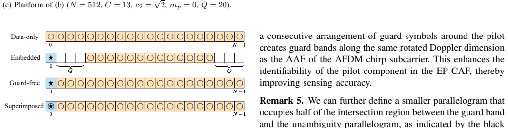
- In bistatic sensing with only the pilot known, the CAF's Doppler shift $\delta_f$ between subcarriers means data subcarriers contribute interference offset by their frequency difference; guard symbols placed around the pilot create an interference-free parallelogram.
- The interference-free parallelogram is strictly smaller than the unambiguity parallelogram, so bistatic guard-symbol sensing demands a narrower delay-Doppler spread or more guard overhead.
- Random-data AFDM frames without pilots retain a thumbtack-like average AAF, so data-only sensing is feasible at the monostatic receiver.
Reading between the lines
- Because every unambiguity parallelogram has area one in delay-Doppler units, tuning $c_1$ only trades unambiguous delay range against Doppler range; the product of the two ranges is fixed by the AFDM time-bandwidth product.
- The AFDM subcarrier grid closely resembles the OTFS subcarrier pulse train, so the same unit-cell reasoning may transfer to other full-resource waveforms; the paper notes the resemblance but does not claim transferability.
- Replacing rectangular shaping with a root-raised-cosine filter (the paper's stated future work) could preserve or distort the unit-area parallelogram; computing the AAF under that shaping would show which properties are intrinsic to AFDM and which depend on rectangular pulses.
Editorial analysis
A structured set of objections, weighed in public.
Referee Report
Summary. The paper analyzes the aperiodic ambiguity functions of continuous-time AFDM signals for integrated sensing and communications. The authors derive closed-form expressions for the auto-ambiguity function (AAF) of a single AFDM chirp subcarrier and for the cross-ambiguity function (CAF) between two different chirp subcarriers. From these expressions they identify a 'spike-like' local pulse with delay and Doppler resolutions approximately Δt and Δf, and a 'periodic-like' global grid of pulses with adjacent spacings Δt and CΔf, each parallelogram having unit area. They then define an unambiguity parallelogram and argue that choosing the chirp parameter c1 (equivalently C) so that all target delay-Doppler shifts lie inside one parallelogram enables unambiguous monostatic sensing. For bistatic sensing they analyze the CAF between a pilot subcarrier and an AFDM frame with pilot, guard, and data symbols, and show that inserting guard symbols creates an interference-free parallelogram. The theoretical results are supported by numerical simulations for selected parameter values.
Significance. If the central structural claims are fully established, the paper provides a useful characterization of AFDM's sensing capabilities and a concrete design guideline for choosing c1 to avoid ambiguity in AFDM-ISAC systems. The derivations start directly from the signal definition and the ambiguity-function integral (12), with no fitted parameters, and the numerical simulations in Sec. VI are consistent with the claimed local and global pulse structure for the cases shown. The comparison with OFDM, SCM, and OTFS subcarriers also gives useful insight into why AFDM chirp subcarriers offer simultaneous delay and Doppler perceptibility. However, the central claims are currently justified only for a restricted delay interval, and the promised extension to all other delay cases is not provided; this gap affects the global pulse-lattice property, the unambiguity parallelogram, and the guard-band interference-free region. With the missing cases supplied, the results would be a solid contribution to waveform design for ISAC.
major comments (3)
- [Sec. III-A, Eq. (18)-(21)] The closed-form AAF in Eq. (21) is derived only for the delay interval τ ∈ [kTSC, min{(TSC − tm,1), tm,1} + kTSC], which has length at most TSC/2 and degenerates to a single point for m = 0. The text states 'due to space limitations, we only demonstrate one representative case, from which the remaining cases can be obtained with minor modifications,' but no such cases or modifications are shown, and no symmetry argument is given. The pulse-lattice structure of Property 2, the pulse spacings in Remark 1, and Corollary 1 all rely on the summation limits and the constructive-interference conditions derived from this one interval. If a different delay interval yields different effective values of qm(t) − qm(t − τ) or different residue phase terms, the pulse grid could shift, acquire extra pulses, or change spacing, which would invalidate the unambiguity parallelogram and Proposition 1. The authors should either derive the closed-form expressions for the remaining delay intervals or provide a rigorous argument that the representative case is sufficient.
- [Sec. IV, Eq. (40)-(44)] The CAF derivation suffers from the same restricted-interval problem as the AAF: Eq. (44) is derived only under τ ∈ [kTSC, min{(TSC − tm1,1), tm,1} + kTSC], along with the condition m > m1. For many subcarrier pairs the interval defined by min{(TSC − tm1,1), tm,1} may be empty, and the paper does not explain how the decomposition in Eq. (43) behaves in those cases. Proposition 2's claim of an additional Doppler shift δf^{m,m1} is obtained from the FA condition in the representative case, and it is not clear that the same shift applies in all other delay intervals. Since the bistatic sensing results in Sec. V-B and the guard-band conclusions depend on the CAF pulse locations, the omission affects load-bearing conclusions beyond Proposition 2 itself.
- [Sec. V-B, Eq. (52)] In Eq. (52), the pilot component of A_{s,φ_{mp}}(τ,ν) is written as |x_p|^2 A_{φ_{mp},φ_{mp}}(τ,ν). According to the definition A_{a,b}(τ,ν) = ∫ a(t) b*(t−τ) e^{-j2πνt} dt, the pilot term should be x_p A_{φ_{mp},φ_{mp}}(τ,ν), not |x_p|^2 times the AAF, because the AAF of the pilot subcarrier already contains the full pilot amplitude and the cross-term between the pilot and data symbols is x_p^* Σ x[m] A_{φ_m,φ_{mp}}(τ,ν). The squared amplitude appears to be an error that changes the relative levels of the pilot and data components and the interpretation of the PDR. This should be corrected and the subsequent remarks checked for consistency.
minor comments (6)
- [Sec. II-C] The word 'Subsitituting' in the sentence before Eq. (10) is a typo and should read 'Substituting'.
- [Sec. III-B] In the discussion following Eq. (30), the expression 'PC−˜qm(τ ) i=0 S i b' appears with a formatting error; it should read 'Σ_{i=0}^{C−q̃_m(τ)} S_i^b'.
- [Sec. IV] The word 'visuallized' in the proof of Proposition 2 should be 'visualized'.
- [Sec. V-B, Fig. 8] The ratio ρ for the EP structure is reported as 45.5%; the manuscript should clarify whether this accounts for both the pilot and guard symbols and should state the number of guard symbols Q used in the figure, since Q is introduced formally just before.
- [Sec. VI] The text mentions 'NOTFS and NOTFS denote the numbers of Doppler and delay bins'; one of these should be MOTFS, and the sentence should be corrected.
- [Sec. VI, Fig. 14] The caption says '265-QAM' but the text likely intends '256-QAM'; please verify and correct.
Circularity Check
No significant circularity: the AAF and CAF expressions are derived from the AF integral and the piecewise AFDM subcarrier definition, with no fitted parameter, renamed input, or self-citation chain carrying the central claim.
full rationale
The paper's central results are derived, not assumed. The AAF in Sec. III-A starts from the AF definition in (12), substitutes the piecewise subcarrier expression in (4), and obtains the closed form (21) by direct integration; the CAF in Sec. IV follows the same route from (39) to (44). The FA and RPDA conditions leading to Properties 1 and 2 are obtained from the derived indicators in (24) and (34), not imported from prior work. Corollary 1's unit-area parallelogram is a geometric consequence of the pulse spacings established in Remarks 1 and 2, and Proposition 1 is an application of that derived periodic grid to the matched-filter superposition in (11). The guard-symbol interference-free result in Sec. V-B follows from the data symbols in G being set to zero, so the CAF contributions of those subcarriers vanish; this is a direct consequence of the frame structure, not a fitted or cited conclusion. Self-citations to prior AFDM work are present, including [39] for the continuous-time piecewise subcarrier model and [15], [22] for background, and some authors overlap with those references; however, the cited pieces are not the target results of this paper, and the continuous-time representation is directly checkable from the discrete definition in (2). The only substantial caveat is that the closed forms are demonstrated for a representative delay interval, (18) and (40), with the paper stating 'due to space limitations, we only demonstrate one representative case, from which the remaining cases can be obtained with minor modifications.' That is a proof-completeness gap, not a circularity: it does not make the shown derivation depend on its own conclusion. Accordingly, the circularity score is 0, with the noted omission belonging to correctness risk rather than circularity.
Assumptions & free parameters
assumptions (6)
- domain assumption The continuous-time AFDM subcarrier model with spectrum wrapping (eqs. (4)-(5)) exactly represents the transmitted chirp.
- domain assumption Rectangular pulse shaping with finite support on [0,T] is used for all chirp subcarriers.
- ad hoc to paper A single representative delay interval (18), and (40) for the CAF, is sufficient; all other delay cases follow with minor modifications.
- domain assumption The sensing channel is a sparse sum of P point targets, each with gain h_i, delay tau_i, and Doppler nu_i (eq. (7)).
- domain assumption Data symbols are independent, zero-mean, and unit-power (eq. (49)).
- domain assumption The chirp parameter satisfies 2N|c1| = C as an integer and N is even.
Cite this review
Pith. "Pith review of Ambiguity Function Analysis of AFDM Signals for Integrated Sensing and Communications." pith.science (2026). https://pith.science/paper/DEIZSHM5
@misc{pith2026250708293,
  author       = {Pith},
  title        = {Pith review of: Ambiguity Function Analysis of AFDM Signals for Integrated Sensing and Communications},
  year         = {2026},
  howpublished = {\url{https://pith.science/paper/DEIZSHM5}},
  note         = {Machine review of arXiv:2507.08293}
}
read the original abstract
Affine frequency division multiplexing (AFDM) is a promising chirp-based waveform with high flexibility and resilience, making it well-suited for next-generation wireless networks, particularly in high-mobility scenarios. In this paper, we investigate the ambiguity functions (AFs) of AFDM signals, which fundamentally characterize their range and velocity estimation capabilities in both monostatic and bistatic settings. Specifically, we first derive the auto-ambiguity function (AAF) of an AFDM chirp subcarrier, revealing its "spike-like" local property and "periodic-like" global property along the rotated delay and Doppler dimensions. This structure naturally forms a parallelogram for each localized pulse of the AAF of the AFDM chirp subcarrier, enabling unambiguous target sensing. Then, we study the cross-ambiguity function (CAF) between two different AFDM chirp subcarriers, which exhibits the same local and global properties as the AAF but with an additional shift along the Doppler dimension. We then extend our analysis to the AF of various typical AFDM frames, considering both deterministic pilot and random data symbols. In particular, we demonstrate that inserting guard symbols in AFDM facilitates interference-free sensing. Simulation results validate our theoretical findings, highlighting AFDM's strong potential for ISAC applications.
Figures


Figures from the paper (10 more)




Reference graph
Works this paper leans on
-
[45]
AFDM-based bistatic integrated sensing and communication in static scatterer environments,
J. Zhu, Y . Tang, F. Liu et al., “AFDM-based bistatic integrated sensing and communication in static scatterer environments,” IEEE Wireless Commun. Lett., vol. 13, no. 8, pp. 2245-2249, 2024
work page 2024
-
[1]
Twelve scientific challenges for 6G: Rethinking the foundations of communications the- ory,
M. Chafii, L. Bariah, S. Muhaidat, and M. Debbah, “Twelve scientific challenges for 6G: Rethinking the foundations of communications the- ory,” IEEE Commun. Surveys Tuts. , vol. 25, no. 2, pp. 868–904, 2023
work page 2023
-
[2]
Performance degradation of OFDM systems due to doppler spreading,
T. Wang, J. G. Proakis, E. Masry, and J. R. Zeidler, “Performance degradation of OFDM systems due to doppler spreading,” IEEE Trans. Wireless Commun., vol. 5, no. 6, pp. 1422-1432, 2006
work page 2006
-
[3]
Draft New Recommendation ITU-R M. [IMT. Frame- work for 2030 and Beyond],
ITU-R WP5D, “Draft New Recommendation ITU-R M. [IMT. Frame- work for 2030 and Beyond],” 2023
work page 2023
-
[4]
Integrated sensing and communications: Toward dual-functional wireless networks for 6G and beyond,
F. Liu, Y . Xiong, S. Lu et al. “Integrated sensing and communications: Toward dual-functional wireless networks for 6G and beyond,” IEEE J. Sel. Areas Commun. , vol. 40, no. 6, pp. 1728–1767, 2022
work page 2022
-
[5]
Orthogonal time frequency space modulation,
R. Hadani, S. Rakib, M. Tsatsanis et al. , “Orthogonal time frequency space modulation,” IEEE Wireless Commun. Netw. Conf. (WCNC) , pp. 1-6, 2017
work page 2017
-
[6]
Orthogonal time-frequency space modulation: A promising next-generation waveform,
Z. Wei, W. Yuan, S. Li et al. , “Orthogonal time-frequency space modulation: A promising next-generation waveform,” IEEE Wireless Commun., vol. 28, no. 4, pp. 136-144, 2021
work page 2021
-
[7]
OTFS-a mathematical foundation for communication and radar sensing in the delay-doppler domain,
S. K. Mohammed, R. Hadani, A. Chockalingam, and R. Calderbank, “OTFS-a mathematical foundation for communication and radar sensing in the delay-doppler domain,” IEEE BITS Inf. Theory Mag. , vol. 2, no. 2, pp. 36-55, 2022
work page 2022
Show all 46 references
-
[8]
Orthogonal delay-doppler division multiplexing modulation,
H. Lin and J. Yuan, “Orthogonal delay-doppler division multiplexing modulation,” IEEE Trans. Wireless Commun. , vol. 21, no. 12, pp. 11 024-11 037, Dec. 2022
2022
-
[9]
Rethinking waveform for 6G: Harness- ing delay-doppler alignment modulation,
Z. Xiao, X. Liu, Y . Zeng et al., “Rethinking waveform for 6G: Harness- ing delay-doppler alignment modulation,” IEEE Commun. Mag. , early access, 2024
2024
-
[10]
OTFS-predictability in the delay-doppler domain and its value to communication and radar sensing,
S. K. Mohammed, R. Hadani, A. Chockalingam, and R. Calderbank, “OTFS-predictability in the delay-doppler domain and its value to communication and radar sensing,” IEEE BITS Inf. Theory Mag. , vol. 3, no. 2, pp. 7-31, 2023
2023
-
[11]
On the effective- ness of OTFS for joint radar parameter estimation and communication,
L. Gaudio, M. Kobayashi, G. Caire, and G. Colavolpe, “On the effective- ness of OTFS for joint radar parameter estimation and communication,” IEEE Trans. Wireless Commun. , vol. 19, no. 9, pp. 5951–5965, 2020
2020
-
[12]
Fundamentals of delay-Doppler com- munications: Practical implementation and extensions to OTFS,
S. Li, P. Jung, W. Yuan et al. , “Fundamentals of delay-Doppler com- munications: Practical implementation and extensions to OTFS,” arXiv preprint arXiv:2403.14192, 2024
2024 arXiv
-
[13]
Delay-doppler alignment modulation for spatially sparse massive MIMO communication,
H. Lu and Y . Zeng, “Delay-doppler alignment modulation for spatially sparse massive MIMO communication,”IEEE Trans. Wireless Commun., vol. 23, no. 6, pp. 6000-6014, 2024
2024
-
[14]
Orthogonal chirp division multiplexing,
X. Ouyang and J. Zhao, “Orthogonal chirp division multiplexing,” IEEE Trans. Commun., vol. 64, no. 9, pp. 3946–3957, 2016
2016
-
[15]
Affine frequency division multiplexing for next-generation wireless communications,
A. Bemani, N. Ksairi, and M. Kountouris, “Affine frequency division multiplexing for next-generation wireless communications,” IEEE Trans. Wireless Commun., vol. 22, no. 11, pp. 8214-8229, 2023
2023
-
[16]
A multicarrier architecture based upon the affine fourier transform,
T. Erseghe, N. Laurenti, and V . Cellini, “A multicarrier architecture based upon the affine fourier transform,” IEEE Trans. Commun. , vol. 53, no. 5, pp. 853-862, May 2005
2005
-
[17]
Affine frequency division multiplex- ing: Extending OFDM for scenario-flexibility and resilience,
H. Yin, Y . Tang, A. Bemani et al., “Affine frequency division multiplex- ing: Extending OFDM for scenario-flexibility and resilience,” accepted by IEEE Wireless Commun. , 2025
2025
-
[18]
H. S. Rou, G. T. F. d. Abreu, J. Choi et al. , “From orthogonal time–frequency space to affine frequency-division multiplexing: A com- parative study of next-generation waveforms for integrated sensing and communications in doubly dispersive channels,” IEEE Signal Process. Mag...
2024
-
[19]
Diagonally reconstructed channel estimation for MIMO-AFDM with inter-doppler interference in doubly selective channels,
H. Yin, X. Wei, Y . Tang, and K. Yang, “Diagonally reconstructed channel estimation for MIMO-AFDM with inter-doppler interference in doubly selective channels,” IEEE Trans. Wireless Commun., vol. 23, no. 10, pp. 14066-14079, 2024
2024
-
[20]
Channel estimation for AFDM with superimposed pilots,
K. Zheng, M. Wen, T. Mao et al., “Channel estimation for AFDM with superimposed pilots,” IEEE Trans. Veh. Technol., vol. 74, no. 2, 2025
2025
-
[21]
GI-free pilot-aided channel estimation for affine frequency division multiplexing systems,
Y . Zhou, H. Yin, N. Zhou et al., “GI-free pilot-aided channel estimation for affine frequency division multiplexing systems,” arXiv preprint arXiv:2404.01088, 2024
2024 arXiv
-
[22]
Evaluation and design criterion for pulse- shaped AFDM,
H. Yin, Y . Tang, S. Li et al., “Evaluation and design criterion for pulse- shaped AFDM,” IEEE Global Commun. Conf. (GLOBECOM), pp. 4944- 4949, 2024
2024
-
[23]
Special cases of DFT-based modulation and demodulation for affine frequency division multiplexing,
V . Savaux, “Special cases of DFT-based modulation and demodulation for affine frequency division multiplexing,” IEEE Trans. Commun., vol. 72, no. 12, pp. 7627-7638, 2024
2024
-
[24]
A simplified affine frequency division multiplexing system for high mobility communications,
J. Du, Y . Tang, H. Yin et al. , “A simplified affine frequency division multiplexing system for high mobility communications,” IEEE Wireless Commun. Netw. Conf. (WCNC) , pp. 1-5, 2024
2024
-
[25]
Cyclic delay-Doppler shift: A simple transmit diversity technique for ultra-reliable communications in doubly selective channels,
H. Yin, Y . Zhou, Y . Tang et al., “Cyclic delay-Doppler shift: A simple transmit diversity technique for ultra-reliable communications in doubly selective channels,” under review in IEEE Trans. Wireless Commun. 2025
2025
-
[26]
Low complexity equalization for AFDM in doubly dispersive channels,
A. Bemani, N. Ksairi, and M. Kountouris, “Low complexity equalization for AFDM in doubly dispersive channels,” IEEE Int. Conf. Acoustics Speech Signal Process. (ICASSP) , pp. 5273-5277, 2022
2022
-
[27]
Chirp parameter selection for affine frequency division multiplexing with MMSE equalization,
Z. Li, C. Zhang, G. Song et al. , “Chirp parameter selection for affine frequency division multiplexing with MMSE equalization,” IEEE Trans. Commun., early access, 2024
2024
-
[28]
AFDM-SCMA: A promising waveform for massive connectivity over high mobility channels,
Q. Luo, P. Xiao, Z. Liu et al., “AFDM-SCMA: A promising waveform for massive connectivity over high mobility channels,” IEEE Trans. Wireless Commun., vol. 23, no. 10, pp. 14421-14436, 2024
2024
-
[29]
DAFT-spread affine frequency division multiple access for downlink transmission,
Y . Tao, M. Wen, Y . Ge et al. , “DAFT-spread affine frequency division multiple access for downlink transmission,” IEEE Global Commun. Conf. (GLOBECOM), pp. 2991-2996, 2024
2024
-
[30]
Design and performance analysis of index modulation empowered AFDM system,
J. Zhu, Q. Luo, G. Chen et al. , “Design and performance analysis of index modulation empowered AFDM system,” IEEE Wireless Commun. Lett., vol. 13, no. 3, pp. 686-690, 2024
2024
-
[31]
Affine frequency division multiplexing with index modulation: Full diversity condition, performance analysis, and low-complexity detection,
Y . Tao, M. Wen, Y . Ge et al. , “Affine frequency division multiplexing with index modulation: Full diversity condition, performance analysis, and low-complexity detection,” IEEE J. Sel. Areas Commun. , vol. 43, no. 4, pp. 1041-1055, 2025
2025
-
[32]
Pre-chirp-domain index modulation for full-diversity affine frequency division multiplexing towards 6G,
G. Liu, T. Mao, Z. Xiao et al., “Pre-chirp-domain index modulation for full-diversity affine frequency division multiplexing towards 6G,” IEEE Trans. Wireless Commun., early access, 2025
2025
-
[33]
AFDM chirp-permutation- index modulation with quantum-accelerated codebook design,
H. S. Rou, K. Yukiyoshi, T. Mikuriya et al., “AFDM chirp-permutation- index modulation with quantum-accelerated codebook design,” Asilomar Conf. Signals Syst. Comput. , pp. 817-821, 2024
2024
-
[34]
Towards integrated sensing and communications for 6G,
Q. Wang, A. Kakkavas, X. Gong and R. A. Stirling-Gallacher, “Towards integrated sensing and communications for 6G,” IEEE Int. Symp. Joint Commun. & Sensing (JC&S) , 2022
2022
-
[35]
Affine frequency division multiplexing for communication and channel sounding: Requirements, challenges, and key technologies,
Y . Zhou, C. Zou, N. Zhou et al., “Affine frequency division multiplexing for communication and channel sounding: Requirements, challenges, and key technologies,” under review in IEEE Veh. Technol. Mag., 2025
2025
-
[36]
An integrated sensing and communi- cations system based on affine frequency division multiplexing,
Y . Ni, P. Yuan, Q. Huang et al., “An integrated sensing and communi- cations system based on affine frequency division multiplexing,” IEEE Trans. Wireless Commun., vol. 24, no. 5, pp. 3763-3779, 2025
2025
-
[37]
Affine frequency division multiplexing for compressed sensing of time-varying chan- nels,
W. Benzine, A. Bemani, N. Ksairi, and D. Slock, “Affine frequency division multiplexing for compressed sensing of time-varying chan- nels,” IEEE Int. Workshop Signal Process. Advances Wireless Commun. (SPAWC), pp. 916-920, 2024
2024
-
[38]
Joint channel, data, and radar parameter estimation for AFDM systems in doubly-dispersive channels,
K. R. R. Ranasinghe, H. Seok Rou, G. Thadeu Freitas de Abreu et al., “Joint channel, data, and radar parameter estimation for AFDM systems in doubly-dispersive channels,” IEEE Trans. Wireless Commun., vol. 24, no. 2, pp. 1602-1619, 2025
2025
-
[39]
Integrated sensing and communications with affine frequency division multiplexing,
A. Bemani, N. Ksairi, and M. Kountouris, “Integrated sensing and communications with affine frequency division multiplexing,” IEEE Wireless Commun. Lett., vol. 13, no. 5, pp. 1255-1259, 2024
2024
-
[40]
A novel angle-delay-Doppler estimation scheme for AFDM-ISAC system in mixed near-field and far- field scenarios,
Y . Luo, Y . L. Guan, Y . Ge et al. , “A novel angle-delay-Doppler estimation scheme for AFDM-ISAC system in mixed near-field and far- field scenarios,” IEEE Internet Things J. , early access, 2025
2025
-
[41]
Pulse shaping for random ISAC signals: The ambiguity function between symbols matters,
Z. Liao, F. Liu, S. Li et al. , “Pulse shaping for random ISAC signals: The ambiguity function between symbols matters,” IEEE Trans. Wireless Commun., vol. 24, no. 4, pp. 2832-2846, 2025
2025
-
[42]
OFDM achieves the low- est ranging sidelobe under random ISAC signaling,
F. Liu, Y . Zhang, Y . Xiong et al. , “OFDM achieves the low- est ranging sidelobe under random ISAC signaling,” arXiv preprint arXiv:2407.06691, 2024
2024 arXiv
-
[43]
Uncovering the iceberg in the sea: Fundamentals of pulse shaping and modulation design for random ISAC signals,
F. Liu, Y . Xiong, S. Lu et al. , “Uncovering the iceberg in the sea: Fundamentals of pulse shaping and modulation design for random ISAC signals,” IEEE Trans. Signal Process. , early access, 2025
2025
-
[44]
From OTFS to DD-ISAC: Integrating sensing and communications in the delay doppler domain,
W. Yuan, L. Zhou, S. K. Dehkordi et al. , “From OTFS to DD-ISAC: Integrating sensing and communications in the delay doppler domain,” IEEE Wireless Commun., vol. 31, no. 6, pp. 152-160, 2024
2024
-
[46]
Hlawatsch and G
F. Hlawatsch and G. Matz, Wireless Communications over Rapidly Time- Varying Channels. Academic Press, 2011
2011
Reviewed August 6, 2026 · model on record in the stance chip above.
Discussion (0). Sign in to comment.