REVIEW 2 major objections 5 minor 50 references
Experimental Demonstration of Exceptional Points of Degeneracy in Linear Time Periodic Systems and Exceptional Sensitivity
T0 review · 2 major / 5 minor · reviewed 2026-08-14 · deepseek-v4-flash
Pith's one-line read A single time-modulated LC resonator hosts an exceptional point whose frequency shift scales as the square root of a small capacitance perturbation.
desk verdict A credible first experimental demonstration of EPDs in a single time-modulated resonator, with a sensitivity experiment that shows the expected square-root trend but rests on an unmeasured calibration that should be checked before the quantitative claim is taken at face value. read the letter →
The pith
A machine-rendered reading of the paper's core claim, the machinery that carries it, and where it could break.
The reading
What carries the argument
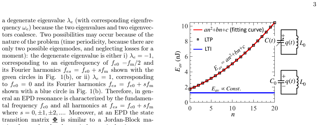
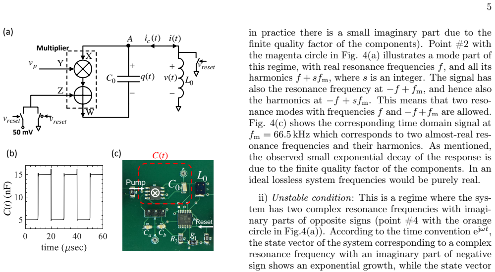
The load-bearing object is the $2\times2$ state transition matrix $\Phi(T_m,0)$ that maps the resonator state, capacitor charge and inductor current, over one modulation period $T_m$. At the EPD, $\Phi$ is non-diagonalizable with a degenerate eigenvalue $\lambda_e=\pm1$, so its $n$-th power grows linearly in the period index $n$; this algebraic growth produces the observed linear voltage rise. The sensitivity law comes from a first-order Puiseux expansion of the perturbed eigenvalues, with coefficient $\alpha_1$ determined by the derivative of $\det[\Phi(\delta)-\lambda I]$. The physical implementation replaces the physical time-varying capacitor with a fixed capacitor $C_0$ and a four-quadrant multiplier that realizes $C(t)=C_0(1-v_p(t)/V_0)$, so the two capacitance levels $C_1$ and $C_2$ are set by the pump voltage levels and the EPD is tuned by the pump frequency $f_m$.
What would settle it
Measure the capacitance $C(t)$ actually presented by the multiplier circuit while the pump high level is swept over the range used in the sensitivity plot, using a direct impedance or bridge measurement; if the true $\delta$ deviates from the assumed linear map, the claimed $\sqrt{\delta}$ scaling and sensitivity enhancement are not established by the current data. Alternatively, apply a known, independently calibrated capacitance change at fixed pump voltage and check that the FFT peaks shift by the predicted $\sqrt{\delta}$ amount.
Extended reading notes
Core claim
The paper's central claim is that an exceptional point of degeneracy can be induced in a single linear time-periodic LC resonator by periodically modulating one capacitance value, and that operating at this EPD makes the resonance frequency exceptionally sensitive to perturbations. Theoretically, the two resonances of the unperturbed time-periodic system coalesce at the EPD, so the state transition matrix becomes a Jordan block; a small perturbation $\delta$ to the capacitance $C_1$ splits the degeneracy with a Puiseux expansion $\lambda_p(\delta)=\lambda_e+(-1)^p\alpha_1\sqrt{\delta}$, giving a detected frequency shift $\Delta f\propto\sqrt{\delta}$. Experimentally, the authors observe both EPD types, at the center and at the edge of the fundamental Brillouin zone, in the dispersion diagram, measure the linear voltage growth characteristic of the degenerate state, and demonstrate that capacitance perturbations as small as 0.3% produce clearly resolvable frequency shifts. The authors argue that this single-resonator EPD is easier to realize and tune than PT-symmetric two-resonator EPDs and that its shifted resonances remain real-valued for a one-sided capacitance perturbation, a practical advantage for sensor readout.
Load-bearing premise
The result depends on the calibration that a 5 mV increase in the pump voltage's high level corresponds exactly to a relative capacitance change of $\delta=0.01$, which follows from the ideal multiplier equation and was not verified by directly measuring the capacitance seen by the circuit.
Editorial extensions
If this is right
- A sensor can be built from a single LC tank with an off-the-shelf multiplier, and the EPD is reached simply by tuning the pump frequency instead of matching gain and loss.
- At the EPD, a relative capacitance perturbation $\delta$ produces a frequency shift proportional to $\sqrt{\delta}$, so a 1% perturbation yields roughly a 10% shift, well above the noise floor observed in the measurements.
- The linear voltage growth at the EPD gives a time-domain signature that can confirm EPD operation and could serve as a second readout channel.
- Because only the modulation frequency needs adjusting, component tolerances in $L$ and $C$ do not prevent reaching the EPD; the sensor can be retuned in situ.
- Unlike a PT-symmetric two-resonator sensor perturbed on one side, this single-resonator EPD keeps the split resonance frequencies real-valued for a capacitance perturbation, simplifying frequency readout.
Reading between the lines
- If the pump-to-capacitance calibration is verified by direct measurement, the same circuit could be packaged as a compact capacitive sensor for pressure, humidity, or biochemical mass, where the quantity of interest changes an effective capacitance.
- The same time-periodic EPD mechanism should extend to higher-order EPDs, for example by using more than two capacitance levels in one modulation cycle, with frequency shifts scaling as $\delta^{1/m}$ and potentially larger sensitivity.
- The experiments leave open a systematic noise study: quantifying how the reset duty cycle, measurement window, and multiplier noise floor affect the minimum resolvable $\delta$ would test whether the $\sqrt{\delta}$ advantage survives at very low signal levels.
Signed reviews
Editorial analysis
A structured set of objections, weighed in public.
Referee Report
Summary. The manuscript reports an experimental demonstration of a second-order exceptional point of degeneracy (EPD) in a single LC resonator whose capacitance is modulated in time through a piecewise-constant pump voltage and an analog multiplier. The authors verify the EPD by two signatures: the measured dispersion diagram of the resonance frequencies versus modulation frequency, and the observed linear growth of the time-domain capacitor voltage at the predicted EPD modulation frequencies. They then perturb the high level of the pump voltage and report that the resonance frequency shifts follow the square-root Puiseux law Δf ∝ √δ, concluding that this provides a single-resonator, easily tunable EPD-based sensor that avoids the precise gain/loss balancing needed in PT-symmetric coupled-resonator schemes. The theoretical framework is a state-transition-matrix analysis carried over from the authors' prior paper [32]; the experimental realization and the sensitivity measurement are the new contributions.
Significance. If the sensitivity result withstands scrutiny, this would be a valuable experimental confirmation that EPDs in linear time-periodic systems can be realized in a single resonator and that the associated fractional frequency shift can be observed in a realistic noisy electronic circuit. The paper has clear strengths: the EPD existence is supported by two independent signatures (the dispersion diagram and the time-domain growth), the frequency-shift prediction in Fig. 5(a) is not a fit because α1 is calculated, and the authors candidly acknowledge the ongoing debate around EPD-enhanced sensing and address the role of noise. The main weakness is that the perturbation δ is not measured but inferred from the ideal multiplier relation, so the quantitative aspect of the exceptional-sensitivity claim is not yet established. The experimental demonstration is also somewhat incremental relative to the authors' earlier theory paper [32], but the hardware realization is a meaningful step toward practical EPD sensors.
major comments (2)
- [Section III.B; Supplemental Eqs. (6)-(10)] The x-axis of Fig. 5(a) is set by assuming an exact linear relation between the pump high-level voltage and the capacitance perturbation δ. The authors infer δ from the ideal multiplier equation C(t)=C0(1−vp(t)/V0) with V0=1.05 V taken from the AD835 datasheet, but no direct measurement of the synthesized capacitance is reported (for example, by measuring ic(t)/[dv/dt] at Node A). A constant multiplier gain or offset error would scale all δ values and move the green triangles off the theoretical curve while preserving the √δ functional form, and a nonlinearity (e.g. multiplier saturation or switch nonidealities) could produce a spurious sub-linear dependence. Because the central sensing claim is the quantitative Δf∝√δ behavior, the δ calibration must be independently measured and the resulting curves must be shown with uncertainties before the 'excellent agreement' assertion in Section III.B is supported.
- [Section III.B and Fig. 5] The sensitivity demonstration reports no quantitative uncertainty. The green triangles in Fig. 5(a) have no error bars, and the text does not state the FFT frequency resolution, the linewidths of the measured peaks, or the run-to-run repeatability across reset cycles. The claim that a δ=0.003 perturbation is 'distinguishable' requires a quantitative comparison between the peak separation and the peak width/noise floor. As written, the data support a qualitative √δ-like trend but do not fully substantiate the quantitative sensitivity enhancement claimed in the abstract and conclusion.
minor comments (5)
- [Section II, Eq. (9)] The rendered formula for α1 is garbled in the manuscript text ('/radical√p/radicalver√ex/...'); the production version should be checked carefully so that the Puiseux coefficient expression is readable.
- [Section III.A and Fig. 4(a)] The slight shift between the theoretical and experimental dispersion curves is attributed to parasitics and tolerances, but no quantitative estimate is given; a number (e.g. the frequency offset at the EPD) would make the 'good agreement' statement more concrete.
- [Section III.B] The sentence 'each 5 mV change in the positive level of the pump voltage will result in 1% change of the C1 capacitor value' relies on the ideal multiplier model and would be better accompanied by a statement of the measured C(t) or at least by a discussion of how the actual multiplier gain and offset were characterized.
- [Figure 5 caption] The phrase 'Proof of exceptional sensitivity' is stronger than the evidence presented; 'Demonstration' or 'Measurement' would be more appropriate.
- [Supplemental Material, Section I] The derivation leading to C(t)=C0(1−vp(t)/V0) ignores the switching transients in vp(t); it would be helpful to state explicitly that the relation is valid away from the switching instants and to comment on any charge-injection effects from the reset switches.
Circularity Check
No circularity: the theoretical EPD and Puiseux prediction are taken from prior work but independently tested by parameter-free comparison with measured FFT peaks.
full rationale
The paper's theoretical framework (state transition matrix, EPD condition, Jordan-block linear growth, and Puiseux expansion) is taken from the same group's earlier work [32] and from general results [33,34], but the experimental content is an independent test of that framework. The EPD is identified by two independent observables: the dispersion diagram (measured resonance frequencies versus modulation frequency) and the linear growth of the capacitor voltage in the time domain. The sensitivity comparison in Fig. 5 is parameter-free: the Puiseux coefficient α1 = j2.65 is calculated from the state transition matrix, and the experimental frequency shifts are obtained from FFT peaks of the measured voltage waveform. The relative perturbation δ is set by changing the pump-voltage high level and converted to a capacitance change using the ideal multiplier relation C(t) = C0(1 − vp(t)/V0) with V0 = 1.05 V from the AD835 datasheet. This calibration is not directly measured and could be a source of experimental error, but it is not circular: the measured frequencies are not used to define δ or to fit the theoretical curve, so the √δ prediction remains falsifiable. Self-citation of [32] is for the Floquet formalism, which this experiment independently validates; no equation reduces to its own input and no fitted parameter is renamed as a prediction.
Assumptions & free parameters
free parameters (1)
- Fitting coefficients for simulated energy growth in Fig. 2 =
a=0.01, b=0.23, c=1.74
assumptions (4)
- standard math Floquet theory: the state transition matrix Phi(Tm,0) determines the evolution and its eigenvalues are exp(j2π f Tm)
- domain assumption The time-varying capacitor is exactly modeled as C(t)=C0(1-vp(t)/V0) with an ideal multiplier and no bandwidth limitations
- standard math The Puiseux series expansion for eigenvalues near an EPD (Ref. [33]) is valid and truncated at first order in sqrt(delta)
- domain assumption The system is approximately lossless except for a small series resistance, so the EPD condition can be applied with a small imaginary part
Cite this review
Pith. "Pith review of Experimental Demonstration of Exceptional Points of Degeneracy in Linear Time Periodic Systems and Exceptional Sensitivity." pith.science (2026). https://pith.science/paper/E5SEWQ3D
@misc{pith2026190808516,
  author       = {Pith},
  title        = {Pith review of: Experimental Demonstration of Exceptional Points of Degeneracy in Linear Time Periodic Systems and Exceptional Sensitivity},
  year         = {2026},
  howpublished = {\url{https://pith.science/paper/E5SEWQ3D}},
  note         = {Machine review of arXiv:1908.08516}
}
read the original abstract
We present the experimental demonstration of the occurrence of exceptional points of degeneracy (EPDs) in a single resonator by introducing a linear time-periodic variation of one of its components, in contrast to EPDs in parity time (PT)-symmetric systems that require two coupled resonators with precise values of gain and loss. In the proposed scheme, only the tuning of the modulation frequency is required that is easily achieved in electronic systems. The EPD is a point in a system parameters' space at which two or more eigenstates coalesce, and this leads to unique properties not occurring at other non-degenerate operating points. We show theoretically and experimentally the existence of a second order EPD in a time-varying single resonator. Furthermore, we measure the sensitivity of the proposed system to a small structural perturbation and show that the operation of the system at an EPD dramatically boosts its sensitivity performance to very small perturbations. Also, we show experimentally how this unique sensitivity induced by an EPD can be used to devise new exceptionally-sensitive sensors based on a single resonator by simply applying time modulation.
Figures

Figures from the paper (4 more)


Reference graph
Works this paper leans on
- [32]
-
[1]
P.-J. Chen, S. Saati, R. Varma, M. S. Humayun, and Y.- C. Tai, Journal of Microelectromechanical Systems19, 721 (2010)
work page 2010
-
[2]
P.-Y. Chen, M. Sakhdari, M. Hajizadegan, Q. Cui, M. M.-C. Cheng, R. El-Ganainy, and A. Alu, Nature Electronics 1, 297 (2018)
work page 2018
-
[3]
T. Q. Trung, S. Ramasundaram, B.-U. Hwang, and N.- E. Lee, Advanced materials28, 502 (2016)
work page 2016
-
[4]
Y.Feng, L.Xie, Q.Chen, andL.-R.Zheng,IEEESensors Journal 15, 3201 (2015)
work page 2015
-
[5]
P.-J. Chen, D. C. Rodger, S. Saati, M. S. Humayun, and Y.-C. Tai, Journal of Microelectromechanical Sys- tems 17, 1342 (2008)
work page 2008
-
[6]
M. Yvanoff and J. Venkataraman, IEEE Transactions on Antennas and Propagation57, 885 (2009)
work page 2009
-
[7]
L. Y. Chen, B. C.-K. Tee, A. L. Chortos, G. Schwartz, V. Tse, D. J. Lipomi, H.-S. P. Wong, M. V. McConnell, and Z. Bao, Nature communications5, 5028 (2014)
work page 2014
Show all 50 references
-
[8]
S.Corrie, J.Coffey, J.Islam, K.Markey, andM.Kendall, Analyst 140, 4350 (2015)
2015
-
[9]
Tseng, B
P. Tseng, B. Napier, L. Garbarini, D. L. Kaplan, and F. G. Omenetto, Advanced Materials30, 1703257 (2018)
2018
-
[10]
Y. J. Zhang, H. Kwon, M.-A. Miri, E. Kallos, H. Cano- Garcia, M. S. Tong, and A. Alu, Physical Review Ap- plied 11, 044049 (2019)
2019
-
[11]
Kazemi, A
H. Kazemi, A. Hajiaghajani, M. Y. Nada, M. Dautta, M. Alshetaiwi, P. Tseng, and F. Capolino, arXiv:1909.03344 (2019)
2019 arXiv
-
[12]
M.A.K.Othman, F.Yazdi, A.Figotin, andF.Capolino, Phys. Rev. B93, 024301 (2016)
2016
-
[13]
M. Y. Nada and F. Capolino, J. Opt. Soc. Am. B37, 2319 (2020)
2020
-
[14]
Veysi, M
M. Veysi, M. A. K. Othman, A. Figotin, and F. Capolino, Physical Review B97, 195107 (2018)
2018
-
[15]
Hodaei, M.-A
H. Hodaei, M.-A. Miri, M. Heinrich, D. N. Christodoulides, and M. Khajavikhan, Science346, 975 (2014)
2014
-
[16]
Oshmarin, F
D. Oshmarin, F. Yazdi, M. A. Othman, J. Sloan, M. Rad- far, M.M.Green, andF.Capolino,IETCircuits, Devices & Systems (2019)
2019
-
[17]
Schindler, A
J. Schindler, A. Li, M. C. Zheng, F. M. Ellis, and T. Kot- tos, Physical Review A84, 040101 (2011)
2011
-
[18]
Chitsazi, H
M. Chitsazi, H. Li, F. Ellis, and T. Kottos, Physical Review Letters 119, 093901 (2017)
2017
-
[19]
Sakhdari, M
M. Sakhdari, M. Hajizadegan, Y. Li, M. Cheng, J. C. H. Hung, and P.-Y. Chen, IEEE Sensors Journal18, 9548 (2018)
2018
-
[20]
Sakhdari, M
M. Sakhdari, M. Hajizadegan, Q. Zhong, D. Christodoulides, R. El-Ganainy, and P.-Y. Chen, Physical Review Letters 123 (2019), 10.1103/phys- revlett.123.193901
2019 doi
-
[21]
Wiersig, Physical Review Letters112, 203901 (2014)
J. Wiersig, Physical Review Letters112, 203901 (2014)
2014
-
[22]
Wiersig, Physical Review A93, 033809 (2016)
J. Wiersig, Physical Review A93, 033809 (2016)
2016
-
[23]
Hodaei, A
H. Hodaei, A. U. Hassan, S. Wittek, H. Garcia-Gracia, R. El-Ganainy, D. N. Christodoulides, and M. Kha- javikhan, Nature 548, 187 (2017)
2017
-
[24]
W. Chen, S. Kaya Ozdemir, G. Zhao, J. Wiersig, and L. Yang, Nature548, 192 (2017)
2017
-
[25]
C. M. Bender and S. Boettcher, Physical Review Letters 80, 5243 (1998)
1998
-
[26]
Stehmann, W
T. Stehmann, W. D. Heiss, and F. G. Scholtz, Journal of Physics A: Mathematical and General37, 7813 (2004)
2004
-
[27]
M. Y. Nada, H. Kazemi, A. F. Abdelshafy, F. Yazdi, D. Oshmarin, T. Mealy, A. Figotin, and F. Capolino, in 2018 18th Mediterranean Microwave Symposium (MMS) (IEEE, 2018) pp. 108–111
2018
-
[28]
M. Y. Nada, M. A. K. Othman, and F. Capolino, Phys- ical Review B96, 184304 (2017)
2017
-
[29]
M. A. K. Othman, M. Veysi, A. Figotin, and F. Capolino, Physics of Plasmas23, 033112 (2016)
2016
-
[30]
A.FigotinandI.Vitebskiy,PhysicalReviewE 72(2005), 10.1103/physreve.72.036619
2005 doi
-
[31]
M. Y. Nada, A. F. Abdelshafy, T. Mealy, F. Yazdi, H. Kazemi, A. Figotin, and F. Capolino, in 2018 In- ternational Conference on Electromagnetics in Advanced Applications (ICEAA) (IEEE, 2018) pp. 627–629
2018
-
[33]
Welters, SIAM Journal on Matrix Analysis and Ap- plications 32, 1 (2011)
A. Welters, SIAM Journal on Matrix Analysis and Ap- plications 32, 1 (2011)
2011
-
[34]
J. A. Richards,Analysis of periodically time-varying sys- tems (Springer, New York, 1983)
1983
-
[35]
Parametric amplifier,
A. Ashkin, J. S. Cook, W. H. Louisell, and C. F. Quate, “Parametric amplifier,” (1960), US Patent 2,958,001
1960
-
[36]
Cassedy and A
E. Cassedy and A. Oliner, Proceedings of the IEEE51, 1342 (1963)
1963
-
[37]
E. M. T. J. R. C. Honey, IEEE Transactions on Mi- crowave Theory and Techniques8, 351 (1960)
1960
-
[38]
J.-C. Lee, H. Taylor, and K. Chang, IEEE Microwave and Guided Wave Letters7, 267 (1997)
1997
-
[39]
Yamamoto, K
T. Yamamoto, K. Inomata, M. Watanabe, K. Matsuba, T. Miyazaki, W. D. Oliver, Y. Nakamura, and J. S. Tsai, Applied Physics Letters93, 042510 (2008)
2008
-
[40]
Langbein, Physical Review A98, 023805 (2018)
W. Langbein, Physical Review A98, 023805 (2018)
2018
-
[41]
Zhang, W
M. Zhang, W. Sweeney, C. W. Hsu, L. Yang, A. Stone, and L. Jiang, Physical Review Letters 123, 180501 10 (2019)
2019
-
[42]
Lau and A
H.-K. Lau and A. A. Clerk, Nature Communications9, 4320 (2018)
2018
-
[43]
Wiersig, Nature Communications11, 2454 (2020)
J. Wiersig, Nature Communications11, 2454 (2020)
2020
-
[44]
Wiersig, Physical Review A101, 053846 (2020)
J. Wiersig, Physical Review A101, 053846 (2020)
2020
-
[45]
Z. Xiao, H. Li, T. Kottos, and A. Alù, Physical Review Letters 123, 213901 (2019). Experimental Demonstration of Exceptional Points of Degeneracy in Linear Time Periodic Systems and Exceptional Sensitivity Hamidreza Kazemi, Mohamed Y. Nada, Alireza Nikzamir, Franco Maddaleno, ...
2019 arXiv
-
[46]
Kazemi, M
H. Kazemi, M. Y. Nada, T. Mealy, A. F. Abdelshafy, and F. Capolino, Phys. Rev. Applied 11, 014007 (2019)
2019
-
[47]
250 MHz, Voltage Output, 4-Quadrant Multiplier, Analog Devices (2019), rev. E
2019
-
[48]
Surface Mount Ceramic Capacitor Products, A VX Corpo- ration (2019)
2019
-
[49]
Shielded Power Inductors-MSS7348, Coilcraft Inc. (2018)
2018
-
[50]
Power-Off Protection±5 V, +12 V, Quad SPST Switches with 5 Ohms On Resistance, Analog Devices (2019), rev. 0
2019
Reviewed August 14, 2026 · model on record in the stance chip above.
Discussion (0). Continue with ORCID to comment.