REVIEW 4 major objections 6 minor 73 references
Optical Footprint of Ghost and Leaky Hyperbolic Polaritons
T0 review · 4 major / 6 minor · reviewed 2026-08-09 · deepseek-v4-flash
Pith's one-line read This paper argues that ghost and leaky hyperbolic polaritons, modes previously observed only with near-field optical microscopy, have identifiable far-field signatures in attenuated total reflection spectra of crystal quartz, and that…
desk verdict Plausible, well-executed TMM study of ATR fingerprints of ghost and leaky hyperbolic polaritons, but the core identification relies on shape-matching to prior near-field work and needs mode-level verification to be fully convincing. read the letter →
The pith
A machine-rendered reading of the paper's core claim, the machinery that carries it, and where it could break.
The reading
What carries the argument
The engine of the calculation is a 4×4 transfer-matrix method for stratified anisotropic media, applied to the prism/air-gap/crystal stack that couples evanescent waves to surface modes. The dielectric tensor of quartz, uniaxial with components $\varepsilon_\parallel$ and $\varepsilon_\perp$, is rotated by two angles: $\varphi$ tilts the anisotropy axis away from the surface normal, and $\beta$ rotates the incidence plane around that axis; the rotated tensor acquires off-diagonal elements. The method returns the full set of reflection coefficients $r_{pp}$, $r_{ps}$, $r_{sp}$, $r_{ss}$, and the paper tracks the total p-polarised reflectance $R_p = R_{pp}+R_{ps}$ as a function of azimuthal angle $\beta$ and reduced in-plane momentum $k_x/k_0$. The spectral 'footprints' are the shapes of the dips in this reflectance: a hyperbola for GHPs and a lens for LHPs, with their position and intensity controlled by $\varphi$, $\beta$, the air gap distance $d$, and the prism index.
What would settle it
Measure the ATR reflectance of a polished quartz slab with the prism/air-gap parameters of the GHP calculation (high-index prism, $d=0.1$ µm, $\varphi=90^\circ$, 460 cm$^{-1}$): if the predicted hyperbola-shaped dip does not appear at the quoted $k_x/k_0$ and $\beta$ values, or if it persists without the air gap, the ghost-polariton assignment fails. A computational falsifier is to compute the complex poles of the reflection coefficient and show that the dips coincide with modes whose Poynting vectors are parallel to the surface (GHP) or tilted into the bulk (LHP).
Extended reading notes
Core claim
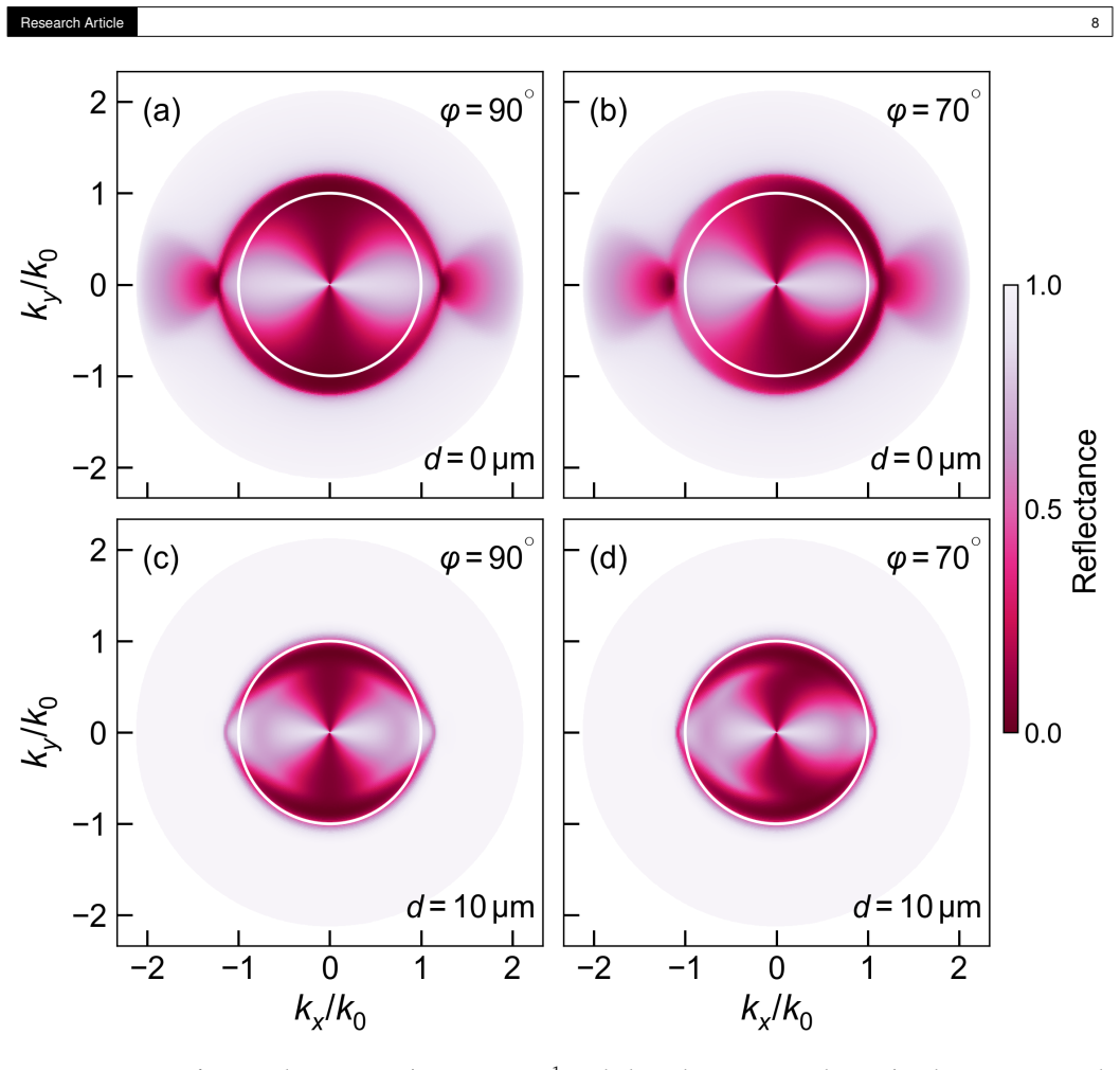
The central claim is that the ghost and leaky hyperbolic polaritons discovered in bulk anisotropic crystals through near-field imaging can be recognised in the far field by their ATR spectra. For GHPs in the Type II hyperbolic region of quartz at 460 cm$^{-1}$, the calculated reflectance, plotted against azimuthal angle and in-plane momentum, shows a hyperbola-shaped dip outside the bulk propagation bands; this is described as mirroring the angular dispersion of the original near-field ghost-polariton observation. For LHPs at 545 cm$^{-1}$, a lenticular dip appears just beyond the critical angle when a 10 µm air gap is introduced, matching the lenticular isofrequency contours seen for leaky polaritons in calcite. When the anisotropy is tilted away from the surface ($\varphi = 60^\circ$ for GHPs, $\varphi = 70^\circ$ for LHPs), the dips shift and weaken, and cross-polarisation conversion becomes strongly asymmetric, with $R_{ps}$ values reaching roughly 0.7 on one side and 0.1 on the other for LHPs. The paper presents this orientation-controlled response as the basis for direction-dependent optical devices.
Load-bearing premise
The load-bearing premise is that the simulated ATR dips really are ghost and leaky hyperbolic polaritons; the paper identifies them by qualitative resemblance to near-field s-SNOM images from earlier experiments, not by a far-field measurement or an independent mode analysis of its own.
Editorial extensions
If this is right
- ATR spectroscopy becomes a far-field, tabletop screening tool for ghost and leaky hyperbolic polaritons in bulk crystals, complementing near-field s-SNOM imaging.
- Rotating the crystal orientation ($\varphi$ and $\beta$) gives a practical way to shift, deepen, or suppress the polariton dips, enabling direction-dependent infrared filters and couplers.
- The large asymmetric cross-polarisation conversion of tilted LHPs could be used for direction-selective or one-way infrared signal routing.
- GHPs respond at high in-plane momenta, so they could serve as wide-field-of-view receivers, while LHPs operate in a narrow momentum window near the light line, suited to directional emitters.
- The same transfer-matrix approach can be applied to shear hyperbolic polaritons and twisted-layer polariton systems to search for analogous far-field fingerprints.
Reading between the lines
- The mode assignment could be tested independently by comparing dip positions with a direct complex-wavevector dispersion calculation of GHPs and LHPs in the same quartz geometry; the paper stops short of such an eigenvalue analysis.
- If the assignment holds, the opening angle of the LHP lenticular dip as the frequency crosses the epsilon-near-zero region could become a contact-free spectroscopic estimator of $\varepsilon_\parallel(\omega)$ in the reststrahlen band.
- Because the GHP and LHP spectra are purely simulated, a high-index-prism ATR experiment with controlled air gap and crystal cut is the natural next step; it would also test the predicted $R_{ps}$ asymmetry of about 0.7 versus 0.1.
- The reciprocal asymmetric cross-polarisation response suggests that a single tilted anisotropic crystal might act as a passive polarization-dependent beam splitter in the infrared, although absorption losses will set the practical efficiency.
Signed reviews
Editorial analysis
A structured set of objections, weighed in public.
Referee Report
Summary. The manuscript studies the attenuated total reflection (ATR) response of crystal quartz in the Otto configuration, with the anisotropy axis tilted by angles φ and β relative to the surface and incidence plane. Using a 4×4 transfer-matrix method, the authors compute reflectance maps over frequency and in-plane wavevector for three polariton classes: ordinary elliptical surface phonon polaritons, ghost hyperbolic polaritons (GHPs), and leaky hyperbolic polaritons (LHPs). They report that GHPs produce a hyperbola-shaped reflectance dip in the Type II hyperbolic region and LHPs produce a lenticular dip in the Type I/ENZ region, with the tilt of the anisotropy axis controlling the shape and the cross-polarization conversion. The paper includes experimental ATR spectra for the ordinary surface-polariton case and compares them to simulations with a fitted air gap, while the GHP and LHP results are purely simulated and are identified by qualitative comparison to prior s-SNOM images.
Significance. If the identification of the simulated reflectance dips as GHPs and LHPs is correct, the paper offers a practical far-field spectroscopic route to probing these recently discovered near-field modes, which could be valuable for device design. The manuscript has several strengths: the 4×4 transfer-matrix formulation is given in full in Appendices A and B; the parameter dependence on air gap, prism permittivity, and anisotropy orientation is explored systematically in Appendices C–H; and the experimental validation for the ordinary elliptical surface polariton provides a baseline check of the numerical method. The claims of direction-dependent cross-polarization conversion are also potentially interesting. However, the central claim is currently supported only by simulated reflectance maps whose mode identity is asserted by shape resemblance to earlier near-field work, not by a mode-level analysis or by far-field experiments on GHPs and LHPs.
major comments (4)
- [Section 2, Figs. 4(b,d) and 5] The hyperbola-shaped reflectance dips in Figs. 4(b,d) and 5 are identified as ghost hyperbolic polaritons solely because their angular shape mirrors the s-SNOM images of Ref. [8]. The transfer-matrix computation returns only the reflected intensity R_p; it does not by itself establish that the minimum corresponds to a ghost mode. In an Otto configuration, a reflectance minimum can also arise from frustrated total internal reflection into bulk hyperbolic modes, from coupling to an ordinary surface phonon polariton with modified dispersion, or from an improper/leaky branch contribution. To support the central claim, the authors should extract the complex pole of r_p (or the relevant eigenvector/eigenvalue of the 4×4 transfer matrix) at the dip and verify the defining GHP characteristics: phase wavefronts slanted away from the surface, Poynting vector parallel to the surface, and evanescent decay away from the surface. A comparison with the analytic dispersion relation of GHPs would also strengthen the identification.
- [Section 3, Figs. 6(b,d) and 7] The same identification issue applies to leaky hyperbolic polaritons. The lenticular reflectance minimum in Figs. 6(b,d) and 7 is linked to the lenticular isofrequency contours of Ref. [11], but the simulation does not demonstrate that the mode at the minimum has the characteristic LHP properties: a complex propagation constant, energy leakage into the bulk, and exponentially growing field behavior in the air gap on the improper branch. Without this mode-level check, the dip could be a bulk-wave artifact or a frustrated-TIR feature. The manuscript should also clarify how a rather thick air gap (d = 10 µm) still permits evanescent coupling to the leaky mode, since the text states that leaky waves grow in air but does not quantify the coupling condition.
- [Abstract and Section 5] The abstract states that 'Our findings reveal that the ATR spectra of GHPs exhibit a distinct hyperbolic behaviour' and that the authors can 'discern the effects of large asymmetry due to cross-polarisation conversion.' However, no experimental ATR data for GHPs or LHPs are presented; the only experimental comparison (Figs. 1(c) and 3) is for ordinary elliptical surface polaritons, and even there the air gap is a fitted parameter (d = 2 µm, with variation 1.5–3 µm). The GHP and LHP conclusions rest entirely on simulations. The authors should either present far-field measurements for these modes or explicitly reframe the claims as theoretical predictions, rather than empirical 'findings.' This distinction is load-bearing for the paper's stated contribution.
- [Section 2, 'In order to obtain the results above' and Fig. 4] The GHP simulations use a prism permittivity of ε_p = 50 (corresponding to k_x/k_0 up to about 7), while the LHP simulations use ε_p = 2.2 and d = 10 µm. These parameter choices are motivated only by the need to reach the relevant wavevector range and are not discussed in terms of physical feasibility or sensitivity. In particular, a prism with ε_p = 50 is far outside the range of common infrared prism materials (e.g., Ge, Si, KRS-5), and the conclusions about direction-dependent behavior depend on this choice. The authors should justify that such parameters are achievable or show that the qualitative conclusions are robust over a range of ε_p and d.
minor comments (6)
- [Fig. 4 caption] The caption for Fig. 4(b) states 'the anisotropy orientation is unchanged (φ = 0◦)' but the text in Section 2 describes the GHP case with φ = 90◦; this is a typographical inconsistency that should be corrected.
- [Appendices D and G] The panel labels in the text and in the captions of Figs. D1 and G1 are inconsistent. For example, in Appendix D the text refers to tilting the anisotropy to φ = 60◦ in Fig. D1(b), while the caption for D1(b) says φ = 90◦, and the air-gap/no-air-gap assignments appear swapped between panels (b) and (c). The same issue affects Fig. G1. These mismatches make the appendix difficult to follow.
- [Fig. 7 and Section 3] The text and figure caption contain an unresolved placeholder: the incident angle is given as 'θ = XX◦', which should be replaced with the actual numerical value.
- [Eq. (3)] Equation (3) uses ε_xx for the in-plane dielectric component, but the surrounding text defines the in-plane components as ε⊥. The notation should be harmonized to avoid ambiguity, especially since later sections use ε_xx, ε_yy, and ε_zz for the rotated tensor.
- [Section 5, experimental methods] The experimental section states that silica spacers of 1.5 µm were used but that the best-fitting theoretical air gap is 2 µm, with variation between 1.5 and 3 µm. The procedure for estimating this uncertainty and its effect on the fitted reflectance should be described more precisely, and the fitted value should be reported with an error bar.
- [Various] There are several typographical errors that should be corrected, including 'between between 450 and 480 cm-1' in the Introduction, 'S-NOM' for 's-SNOM' in Section 2, 'at with a constant' in the captions of Figs. F1 and H1, and the reference to 'Estevam et al.' in the text versus 'Estevâm da Silva' in Ref. [25].
Circularity Check
No circular derivation: the ATR spectra are computed from independent transfer-matrix optics and published quartz permittivity data; the GHP/LHP labels are a comparative interpretation, not an input to the calculation.
full rationale
The load-bearing calculation is the Berreman 4x4 transfer-matrix reflectance (Appendix B) fed by the uniaxial quartz permittivity of Estevam et al. (ref 25), which is external experimental data built on Gervais and Piraeus (ref 73). No GHP or LHP dispersion, field profile, or s-SNOM image enters the calculation as an input; the spectra in Figs. 4-7 are generated before any mode label is attached. The labels are then assigned by qualitative shape comparison to earlier s-SNOM observations: "This highly angular dispersion mirrors that found in the original s-SNOM results of the original GHP discovery [8]" and "We observe a lenticular-shaped drop in reflectivity, indicative of the leaky polariton [11]." That is an interpretive identification step, not a self-referential derivation; the paper does not fit any parameter to the target dips or define GHP/LHP in terms of the ATR minimum. The same-group references (e.g., 5, 25, 34, 35) supply permittivity values and cross-polarisation context, but the central reflectance result does not reduce to a self-citation chain. The skeptical concern that the mode identity is never verified at the eigenvector/Poynting-flux level, and that the only experimental validation is for the ordinary elliptical SPhP, is a validation/completeness limitation, not a circularity. Appendix F's calcite case is also a simulation, but it tests shape correspondence rather than circularity. The derivation is therefore self-contained; at most there are minor self-citations that are not load-bearing, so the circularity burden is very low.
Assumptions & free parameters
free parameters (4)
- Air gap d for experimental comparison =
2 micrometers (best match; variation 1.5-3 micrometers)
- Prism dielectric constant epsilon_p for GHP simulations =
50 (Fig. 4) and 80 (Fig. E1, F1)
- Prism dielectric constant epsilon_p for LHP simulations =
2.2 (Fig. 6) and 4.5 (Fig. G1, H1)
- Air gap d for GHP/LHP simulations =
0.1 micrometers (GHP), 10 micrometers (LHP), 0.5 micrometers (calcite)
assumptions (3)
- standard math Maxwell's equations in CGS with time-harmonic plane waves
- domain assumption Crystal quartz is modeled as a homogeneous uniaxial medium with dielectric tensor parameters from Estevam et al. (ref 25), based on Gervais and Piriou (ref 73)
- ad hoc to paper The modes that produce the simulated ATR dips are the same entities as the GHPs and LHPs observed with s-SNOM in prior work
Cite this review
Pith. "Pith review of Optical Footprint of Ghost and Leaky Hyperbolic Polaritons." pith.science (2026). https://pith.science/paper/ENVCCPSC
@misc{pith2026250118354,
  author       = {Pith},
  title        = {Pith review of: Optical Footprint of Ghost and Leaky Hyperbolic Polaritons},
  year         = {2026},
  howpublished = {\url{https://pith.science/paper/ENVCCPSC}},
  note         = {Machine review of arXiv:2501.18354}
}
read the original abstract
Manipulating hyperbolic polaritons at infrared frequencies has recently garnered interest as it promises to deliver new functionality for next-generation optical and photonic devices. This study investigates the impact of the crystal's anisotropy orientation on the Attenuated Total Reflection (ATR) spectra, more specifically, revealing the optical footprint of elliptical, ghost (GHP) and leaky (LHP) hyperbolic polaritons. Our findings reveal that the ATR spectra of GHPs exhibit a distinct hyperbolic behaviour which is similar to that recently observed using s-SNOM techniques. Similarly, the ATR spectra of LHPs show its clear lenticular behaviour; however, here we are able to discern the effects of large asymmetry due to cross-polarisation conversion when the crystal anisotropy is tilted away from the surface. Furthermore, we demonstrate that by controlling the anisotropy orientation of hyperbolic media it is possible to significantly alter the optical response of these polaritons. Thus, our results provide a foundation for the design of direction-dependent optical devices.
Figures


Figures from the paper (4 more)



Reference graph
Works this paper leans on
-
[8]
Ghost hyperbolic surface polaritons in bulk anisotropic crystals,
W. Ma, G. Hu, D. Hu, et al., “Ghost hyperbolic surface polaritons in bulk anisotropic crystals,” Nature 596, 362–366 (2021). Number: 7872 Publisher: Nature Publishing Group
work page 2021
-
[11]
Observation of directional leaky polaritons at anisotropic crystal interfaces,
X. Ni, G. Carini, W. Ma, et al., “Observation of directional leaky polaritons at anisotropic crystal interfaces,” Nat. Commun. 14, 2845 (2023). Number: 1 Publisher: Nature Publishing Group
work page 2023
-
[1]
Steering and cloaking of hyperbolic polaritons at deep-subwavelength scales,
H. Teng, N. Chen, H. Hu, et al., “Steering and cloaking of hyperbolic polaritons at deep-subwavelength scales,” Nat. Commun. 15, 4463 (2024). Publisher: Nature Publishing Group
work page 2024
-
[2]
Ultrafast anisotropic dynamics of hyperbolic nanolight pulse propagation,
X. Zhang, Q. Y an, W. Ma,et al., “Ultrafast anisotropic dynamics of hyperbolic nanolight pulse propagation,” Sci. Adv. 9, eadi4407 (2023). Publisher: American Association for the Advancement of Science
work page 2023
-
[3]
Real-space nanoimaging of hyperbolic shear polaritons in a monoclinic crystal,
G. Hu, W. Ma, D. Hu,et al., “Real-space nanoimaging of hyperbolic shear polaritons in a monoclinic crystal,” Nat. Nanotechnol. 18, 64–70 (2023). Number: 1 Publisher: Nature Publishing Group
work page 2023
-
[4]
Chapter Two - Negative Refraction and Imaging from Natural Crystals with Hyperbolic Dispersion,
T. Dumelow, “Chapter Two - Negative Refraction and Imaging from Natural Crystals with Hyperbolic Dispersion,” inSolid State Physics, vol. 67 R. E. Camley and R. L. Stamps, eds. (Academic Press, 2016), pp. 103–182
work page 2016
-
[5]
Oriented Asymmetric Wave Propagation and Refraction Bending in Hyperbolic Media,
R. Macêdo, T. Dumelow, R. E. Camley, and R. L. Stamps, “Oriented Asymmetric Wave Propagation and Refraction Bending in Hyperbolic Media,” ACS Photonics 5, 5086–5094 (2018). Publisher: American Chemical Society
work page 2018
-
[6]
Fundamentals of Polaritons in Strongly Anisotropic Thin Crystal Layers,
K. V. Voronin, G. Álvarez Pérez, C. Lanza,et al., “Fundamentals of Polaritons in Strongly Anisotropic Thin Crystal Layers,” ACS Photonics11, 550–560 (2024). Publisher: American Chemical Society
work page 2024
Show all 73 references
-
[7]
Unique ghost surface phonon polaritons in biaxially hyperbolic materials,
Q. Zhang, S.-P . Hao, H.-Y . Song,et al., “Unique ghost surface phonon polaritons in biaxially hyperbolic materials,” Opt. Express 31, 43821–43837 (2023). Publisher: Optica Publishing Group
2023
-
[9]
Volume-Confined Hyperbolic Polaritons and Surface-Confined Hyperbolic Polaritons in Ultrathin Hyperbolic Sheets and Their Identification,
Y . Sun, B. Wu, K. Shi,et al., “Volume-Confined Hyperbolic Polaritons and Surface-Confined Hyperbolic Polaritons in Ultrathin Hyperbolic Sheets and Their Identification,” Eng. Sci. Volume 20 (December 2022) , 157–161 (2022). Publisher: Engineered Science Publisher
2022
-
[10]
Hybridized Hyperbolic Surface Phonon Polaritons at α-MoO3 and Polar Dielectric Interfaces,
Q. Zhang, Q. Ou, G. Hu, et al., “Hybridized Hyperbolic Surface Phonon Polaritons at α-MoO3 and Polar Dielectric Interfaces,” Nano Lett. 21, 3112–3119 (2021). Publisher: American Chemical Society
2021
-
[12]
Manipulation and Steering of Hyperbolic Surface Polaritons in Hexagonal Boron Nitride,
S. Dai, M. Tymchenko, Y . Y ang,et al., “Manipulation and Steering of Hyperbolic Surface Polaritons in Hexagonal Boron Nitride,” Adv. Mater. (Deerfield Beach, Fla.) 30, e1706358 (2018)
2018
-
[13]
Surface phonon-polaritons on general crystal cuts of α-quartz observed by attenuated total reflection,
E. Schuller, G. Borstel, and H. J. Falge, “Surface phonon-polaritons on general crystal cuts of α-quartz observed by attenuated total reflection,” physica status solidi (b) 69, 467–476 (1975). _eprint: https://onlinelibrary.wiley.com/doi/pdf/10.1002/pssb.2220690218
1975 doi
-
[14]
Cladding-Free Hyperbolic Waveguide Arrays,
W. Ji, J. Luo, T. Song,et al., “Cladding-Free Hyperbolic Waveguide Arrays,” ACS Photonics11, 2422–2429 (2024). Publisher: American Chemical Society
2024
-
[15]
Highly-Controllable Plasmon–Phonon Polaritons in Nonlinear-Graphene-LiF Waveguides,
M. B. Heydari, A. Abdollahi, and S. Asgari, “Highly-Controllable Plasmon–Phonon Polaritons in Nonlinear-Graphene-LiF Waveguides,” Plasmonics (2024)
2024
-
[16]
Hyperbolic Phonon Polaritons and Wave Vector Direction-Dependent Dielectric Tensors in Anisotropic Crystals,
Y . Fang, H. Chen, Z. Li, and W. Wang, “Hyperbolic Phonon Polaritons and Wave Vector Direction-Dependent Dielectric Tensors in Anisotropic Crystals,” The J. Phys. Chem. C 128, 7359–7369 (2024). Publisher: American Chemical Society
2024
-
[17]
Observation of naturally canalized phonon polaritons in LiV2O5 thin layers,
A. I. F . Tresguerres-Mata, C. Lanza, J. Taboada-Gutiérrez,et al., “Observation of naturally canalized phonon polaritons in LiV2O5 thin layers,” Nat. Commun. 15, 2696 (2024). Publisher: Nature Publishing Group
2024
-
[18]
Negative refraction inspired polariton lens in van der Waals lateral heterojunctions,
Q. Zhang, Z. Zhen, Y . Y ang,et al., “Negative refraction inspired polariton lens in van der Waals lateral heterojunctions,” Appl. Phys. Lett.114, 221101 (2019). Publisher: American Institute of Physics
2019
-
[19]
Reflection and Refraction of Electrostatic Waves at Hyperbolic Surfaces,
A. Moradi, “Reflection and Refraction of Electrostatic Waves at Hyperbolic Surfaces,” in Theory of Electrostatic Waves in Hyperbolic Metamaterials, A. Moradi, ed. (Springer Nature Switzerland, Cham, 2023), Springer Series in Optical Sciences, pp. 63–85
2023
-
[20]
Optical topological transition and refraction control in crystal quartz by tilting the optical axis,
F . Wu and X. Wu, “Optical topological transition and refraction control in crystal quartz by tilting the optical axis,” JOSA B38, 1452–1456 (2021). Publisher: Optica Publishing Group
2021
-
[21]
Controlling the propagation asymmetry of hyperbolic shear polaritons in beta-gallium oxide,
J. Matson, S. Wasserroth, X. Ni, et al., “Controlling the propagation asymmetry of hyperbolic shear polaritons in beta-gallium oxide,” Nat. Commun. 14, 5240 (2023). Number: 1 Publisher: Nature Publishing Group
2023
-
[22]
Controlling asymmetric transmission in layered natural hyperbolic crystals,
R. Jones, R. E. Camley, and R. Macêdo, “Controlling asymmetric transmission in layered natural hyperbolic crystals,” Opt. & Laser Technol.161, 109210 (2023)
2023
-
[23]
Hyperbolic shear polaritons in low-symmetry crystals,
N. C. Passler, X. Ni, G. Hu, et al., “Hyperbolic shear polaritons in low-symmetry crystals,” Nature 602, 595–600 (2022). Number: 7898 Publisher: Nature Publishing Group
2022
-
[24]
A. Mock, S. Richter, A. Papamichail, et al. , “Effective uniaxial dielectric function tensor and optical phonons in ($\overline{2}01$)-oriented $\ensuremath{\beta}$-${\mathrm{Ga}}_{2}{\mathrm{O}}_{3}$ films with equally distributed sixfold-rotation domains,” Phys. Rev. Appl. 2...
2024
-
[25]
Far-infrared slab lensing and subwavelength imaging in crystal quartz,
R. Estevâm da Silva, R. Macêdo, T. Dumelow,et al., “Far-infrared slab lensing and subwavelength imaging in crystal quartz,” Phys. Rev. B86, 155152 (2012). Publisher: American Physical Society
2012
-
[26]
Strong Coupling between Moiré-Type Plasmons and Phonons in Suspended Monolayer Metallic Twisted Superlattices,
B. Y ou, Y . Du, S. Yuan,et al., “Strong Coupling between Moiré-Type Plasmons and Phonons in Suspended Monolayer Metallic Twisted Superlattices,” Nano Lett. (2024). Publisher: American Chemical Society
2024
-
[27]
Active tuning of anisotropic phonon polaritons in natural van der Waals crystals with negative permittivity substrates and its application in energy transport,
S. Chen, X. Wu, and C. Fu, “Active tuning of anisotropic phonon polaritons in natural van der Waals crystals with negative permittivity substrates and its application in energy transport,” Opto-Electronic Sci. pp. 240002–19 (2024). Publisher: Opto-Electronic Science
2024
-
[28]
Engineering terahertz surface magnon-polaritons in hyperbolic antiferromagnets,
R. Macêdo and R. E. Camley, “Engineering terahertz surface magnon-polaritons in hyperbolic antiferromagnets,” Phys. Rev. B 99, 014437 (2019). Publisher: American Physical Society
2019
-
[29]
Surface magnon polaritons in insulating ferromagnets in out-of-plane configuration,
X.-g. Wang, Y . Zhang, S. Hao,et al., “Surface magnon polaritons in insulating ferromagnets in out-of-plane configuration,” J. Magn. Magn. Mater.570, 170511 (2023)
2023
-
[30]
Surface magnon-polaritons at a dielectric/graphene/gyromagnetic interface in a perpendicular applied magnetic field,
L. Q. Dantas, M. S. Vasconcelos, D. H. A. L. Anselmo, and M. G. Cottam, “Surface magnon-polaritons at a dielectric/graphene/gyromagnetic interface in a perpendicular applied magnetic field,” J. Physics: Condens. Matter 35, 375801 (2023). Publisher: IOP Publishing
2023
-
[31]
Strongly Coupled Magnon–Plasmon Polaritons in Graphene-Two-Dimensional Ferromagnet Heterostructures,
A. T. Costa, M. I. Vasilevskiy, J. Fernández-Rossier, and N. M. R. Peres, “Strongly Coupled Magnon–Plasmon Polaritons in Graphene-Two-Dimensional Ferromagnet Heterostructures,” Nano Lett. 23, 4510–4515 (2023). Publisher: American Chemical Society
2023
-
[32]
Hybrid plasmon-magnon polaritons in graphene-antiferromagnet heterostructures,
Y . V. Bludov, J. N. Gomes, G. A. Farias,et al., “Hybrid plasmon-magnon polaritons in graphene-antiferromagnet heterostructures,” 2D Mater. 6, 045003 (2019). Publisher: IOP Publishing
2019
-
[33]
Reflection and refraction by uniaxial crystals,
J. Lekner, “Reflection and refraction by uniaxial crystals,” J. Physics: Condens. Matter 3, 6121 (1991)
1991
-
[34]
Asymmetric Reflection Induced in Reciprocal Hyperbolic Materials,
X. Wu, C. A. McEleney, Z. Shi, et al., “Asymmetric Reflection Induced in Reciprocal Hyperbolic Materials,” ACS Photonics 9, 2774–2782 (2022). Publisher: Research Article 3 American Chemical Society
2022
-
[35]
Emergent asymmetries and enhancement in the absorption of natural hyperbolic crystals,
X. Wu, C. A. McEleney, M. González-Jiménez, and R. Macêdo, “Emergent asymmetries and enhancement in the absorption of natural hyperbolic crystals,” Optica 6, 1478–1483 (2019). Publisher: Optica Publishing Group
2019
-
[36]
Layer-resolved absorption of light in arbitrarily anisotropic heterostructures,
N. C. Passler, M. Jeannin, and A. Paarmann, “Layer-resolved absorption of light in arbitrarily anisotropic heterostructures,” Phys. Rev. B101, 165425 (2020). Publisher: American Physical Society
2020
-
[37]
Layer-resolved resonance intensity of evanescent polariton modes in anisotropic multilayers,
N. C. Passler, X. Ni, G. Carini, et al., “Layer-resolved resonance intensity of evanescent polariton modes in anisotropic multilayers,” Phys. Rev. B107, 235426 (2023). Publisher: American Physical Society
2023
-
[38]
Topological polaritons and photonic magic angles in twisted alpha-MoO3 bilayers,
G. Hu, Q. Ou, G. Si, et al., “Topological polaritons and photonic magic angles in twisted alpha-MoO3 bilayers,” Nature582, 209–213 (2020). Number: 7811 Publisher: Nature Publishing Group
2020
-
[39]
Two-dimensional natural hyperbolic materials: from polaritons modulation to applications,
G. Jia, J. Luo, H. Wang, et al., “Two-dimensional natural hyperbolic materials: from polaritons modulation to applications,” Nanoscale14, 17096–17118 (2022). Publisher: The Royal Society of Chemistry
2022
-
[40]
Polaritons in layered two-dimensional materials,
T. Low, A. Chaves, J. D. Caldwell,et al., “Polaritons in layered two-dimensional materials,” Nat. Mater.16, 182–194 (2017). Number: 2 Publisher: Nature Publishing Group
2017
-
[41]
Twisted Nano-Optics: Manipulating Light at the Nanoscale with Twisted Phonon Polaritonic Slabs,
J. Duan, N. Capote-Robayna, J. Taboada-Gutiérrez,et al., “Twisted Nano-Optics: Manipulating Light at the Nanoscale with Twisted Phonon Polaritonic Slabs,” Nano Lett. 20, 5323–5329 (2020). Publisher: American Chemical Society
2020
-
[42]
Twisted Polaritonic Crystals in Thin van der Waals Slabs,
N. Capote-Robayna, O. G. Matveeva, V. S. Volkov,et al., “Twisted Polaritonic Crystals in Thin van der Waals Slabs,” Laser & Photonics Rev.16, 2200428 (2022). _eprint: https://onlinelibrary.wiley.com/doi/pdf/10.1002/lpor.202200428
2022 doi
-
[43]
Ultralow-Loss Phonon Polaritons in the Isotope-Enriched alpha-MoO3,
Y . Zhao, J. Chen, M. Xue,et al., “Ultralow-Loss Phonon Polaritons in the Isotope-Enriched alpha-MoO3,” Nano Lett. 22, 10208–10215 (2022). Publisher: American Chemical Society
2022
-
[44]
Atomic-scale photonic hybrids for mid-infrared and terahertz nanophotonics,
J. D. Caldwell, I. Vurgaftman, J. G. Tischler,et al., “Atomic-scale photonic hybrids for mid-infrared and terahertz nanophotonics,” Nat. Nanotechnol. 11, 9–15 (2016). Number: 1 Publisher: Nature Publishing Group
2016
-
[45]
Ghost surface polaritons at oblique antiferromagnetic surface,
S. Hao, Q. Liu, S. Fu, et al., “Ghost surface polaritons at oblique antiferromagnetic surface,” Results Phys.51, 106636 (2023)
2023
-
[46]
Ghost surface polaritons in naturally uniaxial hyperbolic materials,
X.-G. Wang, S.-P . Hao, S.-F . Fu,et al., “Ghost surface polaritons in naturally uniaxial hyperbolic materials,” JOSA B40, 1667–1673 (2023). Publisher: Optica Publishing Group
2023
-
[47]
Visible-frequency hyperbolic plasmon polaritons in a natural van der Waals crystal,
G. Venturi, A. Mancini, N. Melchioni, et al., “Visible-frequency hyperbolic plasmon polaritons in a natural van der Waals crystal,” Nat. Commun.15, 9727 (2024). Publisher: Nature Publishing Group
2024
-
[48]
Ghost Line Waves,
M. Moccia, G. Castaldi, A. Alù, and V. Galdi, “Ghost Line Waves,” ACS Photonics 10, 1866–1872 (2023). Publisher: American Chemical Society
2023
-
[49]
Leaky-wave antennas I: Rectangular waveguides,
L. Goldstone and A. Oliner, “Leaky-wave antennas I: Rectangular waveguides,” IRE Trans. on Antennas Propag. 7, 307–319 (1959). Conference Name: IRE Transactions on Antennas and Propagation
1959
-
[50]
Guided waves on sinusoidally-modulated reactance surfaces,
A. Oliner and A. Hessel, “Guided waves on sinusoidally-modulated reactance surfaces,” IRE Trans. on Antennas Propag.7, 201–208 (1959). Conference Name: IRE Transactions on Antennas and Propagation
1959
-
[51]
Leaky waves in planar optical waveguides,
T. Tamir, “Leaky waves in planar optical waveguides,” Nouvelle Revue d’Optique 6, 273 (1975)
1975
-
[52]
Leaky-Wave Theory, Techniques, and Applications: From Microwaves to Visible Frequencies,
F . Monticone and A. Alu, “Leaky-Wave Theory, Techniques, and Applications: From Microwaves to Visible Frequencies,” Proc. IEEE103, 793–821 (2015)
2015
-
[53]
Lateral Displacement of Optical Beams at Multilayered and Periodic Structures*,
T. Tamir and H. L. Bertoni, “Lateral Displacement of Optical Beams at Multilayered and Periodic Structures*,” JOSA61, 1397–1413 (1971). Publisher: Optica Publishing Group
1971
-
[54]
Epsilon-near-zero metamaterials and electromagnetic sources: Tailoring the radiation phase pattern,
A. Alù, M. G. Silveirinha, A. Salandrino, and N. Engheta, “Epsilon-near-zero metamaterials and electromagnetic sources: Tailoring the radiation phase pattern,” Phys. Rev. B 75, 155410 (2007). Publisher: American Physical Society
2007
-
[55]
Controlled leaky wave radiation from anisotropic epsilon near zero metamaterials,
K. Halterman, S. Feng, and V. C. Nguyen, “Controlled leaky wave radiation from anisotropic epsilon near zero metamaterials,” Phys. Rev. B84, 075162 (2011). Publisher: American Physical Society
2011
-
[56]
Dispersion of Phonon-Like Surface Polaritons on Quartz Observed by Attenuated Total Reflection,
H. J. Falge and A. Otto, “Dispersion of Phonon-Like Surface Polaritons on Quartz Observed by Attenuated Total Reflection,” physica status solidi (b)56, 523–534 (1973). _eprint: https://onlinelibrary.wiley.com/doi/pdf/10.1002/pssb.2220560213
1973 doi
-
[57]
Attenuated total reflection study of bulk and surface polaritons in antiferromagnets and hexagonal ferrites: Propagation at arbitrary angles,
N. R. Anderson and R. E. Camley, “Attenuated total reflection study of bulk and surface polaritons in antiferromagnets and hexagonal ferrites: Propagation at arbitrary angles,” J. Appl. Phys. 113, 013904 (2013). Publisher: American Institute of Physics
2013
-
[58]
Long-Lived Phonon Polaritons in Hyperbolic Materials,
G. Ni, A. S. McLeod, Z. Sun, et al., “Long-Lived Phonon Polaritons in Hyperbolic Materials,” Nano Lett. 21, 5767–5773 (2021). Publisher: American Chemical Society
2021
-
[59]
Leaky-Wave Structures and Techniques for Integrated Front-End Antenna Systems,
D. Zheng, C. H. Chan, and K. Wu, “Leaky-Wave Structures and Techniques for Integrated Front-End Antenna Systems,” IEEE J. Microwaves3, 368–397 (2023). Conference Name: IEEE Journal of Microwaves
2023
-
[60]
Anisotropy and Modal Hybridization in Infrared Nanophotonics Using Low-Symmetry Materials,
M. He, T. G. Folland, J. Duan,et al., “Anisotropy and Modal Hybridization in Infrared Nanophotonics Using Low-Symmetry Materials,” ACS Photonics 9, 1078–1095 (2022). Publisher: American Chemical Society
2022
-
[61]
Twist-Induced Hyperbolic Shear Metasurfaces,
S. Yves, E. Galiffi, X. Ni, et al., “Twist-Induced Hyperbolic Shear Metasurfaces,” Phys. Rev. X14, 021031 (2024). Publisher: American Physical Society
2024
-
[62]
Strong chirality and asymmetric transmission effect in twisted bilayer α-MoO3 in terahertz band,
Y . Wang, M. Wang, B. Wu,et al., “Strong chirality and asymmetric transmission effect in twisted bilayer α-MoO3 in terahertz band,” Opt. & Laser Technol. 174, 110581 (2024)
2024
-
[63]
Twistronics-based polarization engineering,
M. Orazbay and C. Valagiannopoulos, “Twistronics-based polarization engineering,” Phys. Rev. Appl.22, 054028 (2024). Publisher: American Physical Society
2024
-
[64]
Twisted hyperbolic van der Waals crystals for chip-scale full Stokes mid-infrared polarization detection,
N. R. Sahoo, S. S. J. Prasath, B. Kumar, and A. Kumar, “Twisted hyperbolic van der Waals crystals for chip-scale full Stokes mid-infrared polarization detection,” J. Phys. D: Appl. Phys. 57, 505104 (2024). Publisher: IOP Publishing
2024
-
[65]
Unidirectional Ray Polaritons in Twisted Asymmetric Stacks,
J. Álvarez Cuervo, M. Obst, S. Dixit, et al. , “Unidirectional Ray Polaritons in Twisted Asymmetric Stacks,” (2024). ArXiv:2403.18657 [cond-mat, physics:physics]
2024 arXiv
-
[66]
Molding Broadband Dispersion in Twisted Trilayer Hyperbolic Polaritonic Surfaces,
C. Zheng, G. Hu, X. Liu, et al., “Molding Broadband Dispersion in Twisted Trilayer Hyperbolic Polaritonic Surfaces,” ACS Nano16, 13241–13250 (2022). Publisher: American Chemical Society
2022
-
[67]
Phonon Polaritons in Twisted Double-Layers of Hyperbolic van der Waals Crystals,
Z. Zheng, F . Sun, W. Huang,et al., “Phonon Polaritons in Twisted Double-Layers of Hyperbolic van der Waals Crystals,” Nano Lett.20, 5301–5308 (2020). Publisher: American Chemical Society
2020
-
[68]
Optics in Stratified and Anisotropic Media: 4×4-Matrix Formulation,
D. W. Berreman, “Optics in Stratified and Anisotropic Media: 4×4-Matrix Formulation,” JOSA 62, 502–510 (1972). Publisher: Optica Publishing Group
1972
-
[69]
Electromagnetic propagation in birefringent layered media,
P . Y eh, “Electromagnetic propagation in birefringent layered media,” JOSA69, 742–756 (1979). Publisher: Optica Publishing Group
1979
-
[70]
Optical Waves in Layered Media,
P . Y eh and M. Hendry, “Optical Waves in Layered Media,” Phys. Today43, 77–78 (1990)
1990
-
[71]
Optics of anisotropic layered media: A new 4 × 4 matrix algebra,
P . Y eh, “Optics of anisotropic layered media: A new 4 × 4 matrix algebra,” Surf. Sci.96, 41–53 (1980)
1980
-
[72]
Polarization-dependent optical parameters of arbitrarily anisotropic homogeneous layered systems,
M. Schubert, “Polarization-dependent optical parameters of arbitrarily anisotropic homogeneous layered systems,” Phys. Rev. B53, 4265–4274 (1996). Publisher: American Physical Society. Research Article 4
1996
-
[73]
Temperature dependence of transverse and longitudinal optic modes in the $\ensuremath{\alpha}$ and $\ensuremath{\beta}$ phases of quartz,
F . Gervais and B. Piriou, “Temperature dependence of transverse and longitudinal optic modes in the $\ensuremath{\alpha}$ and $\ensuremath{\beta}$ phases of quartz,” Phys. Rev. B 11, 3944–3950 (1975). Publisher: American Physical Society
1975
Reviewed August 9, 2026 · model on record in the stance chip above.
Discussion (0). Continue with ORCID to comment.