REVIEW 1 major objections 4 minor 33 references
An Analytical and Rigorous Method for Analysis of an Array of Magnetically-Biased Graphene Ribbons
T0 review · 1 major / 4 minor · reviewed 2026-08-14 · deepseek-v4-flash
Pith's one-line read Closed-form expressions give the full reflection, transmission, and Faraday rotation of an array of magnetically biased graphene ribbons under normal incidence.
desk verdict Solid analytical extension of graphene-ribbon scattering to the magnetically biased case, with honest limits and a D-sweep gap worth checking before relying on the closed forms. read the letter →
The pith
A machine-rendered reading of the paper's core claim, the machinery that carries it, and where it could break.
The reading
What carries the argument
The load-bearing object is the quasi-static periodic Green's function, whose leading term for a subwavelength array is $G(x)\simeq 1/(2jk_0D)$, a constant independent of position. This constant converts the integral equations for the surface currents into algebraic equations for the average currents $I_x$ and $I_y$. The current profile itself is carried by the single-ribbon eigenfunctions $\psi_n(x)$ and eigenvalues $q_n$ defined by equation (24), with the magnetic field entering through the conductivity tensor components $\sigma_{xx}$, $\sigma_{yy}$, and $\sigma_{xy}$. Each eigenmode contributes an admittance $Y_n=\sigma_{xx}(2j\omega\varepsilon_0/q_n)/(\sigma_{xx}+2j\omega\varepsilon_0/q_n)$, so a resonance appears whenever $q_n\sigma_{xx}+2j\omega\varepsilon_0$ is small; only odd modes couple to the normally incident field. The self-consistent average current then yields the closed-form reflection and transmission coefficients.
What would settle it
Run a rigorous full-wave simulation of the same structure at a fill factor near 0.9 (for example $D=10\,\mu\mathrm{m}$, $w=9\,\mu\mathrm{m}$, $E_f=0.3$ eV, $\tau=1$ ps, $B_0=7.5$ T) and compare the first reflection-resonance frequency and the Faraday rotation angle with equations (40)-(43); if the predicted resonance shifts by more than the few percent the paper reports at lower fill factors, or if extra resonances appear, the constant-term truncation of the periodic Green's function is the point of failure.
Extended reading notes
Core claim
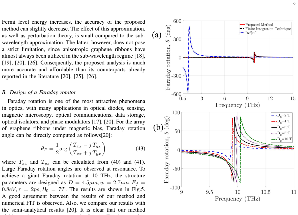
The central claim is that for a subwavelength periodic array of magnetically biased graphene ribbons under normal incidence, the scattering problem has an explicit algebraic answer. With the surface conductivity tensor of biased graphene, the induced $x$-directed current is expanded in the eigenmodes $\psi_n$ of the single-ribbon integral operator, while the $y$-directed current follows from a simple algebraic relation once the average $x$-current is known. The array enters only through a constant term in the periodic Green's function, $1/(2jk_0D)$, which makes the interaction between ribbons a self-consistent constant field rather than a mode-mixing interaction. This leads to equations (40)-(42) for the four reflection and transmission coefficients and equation (43) for the Faraday rotation angle. The paper argues these expressions agree well with full-wave simulations and, unlike the effective-medium approximation, capture the magnetoplasmon resonances of the array.
Load-bearing premise
The load-bearing premise is that the array is deeply subwavelength ($k_0D\ll 1$) and that neighboring ribbons interact only through a constant term in the periodic Green's function, leaving the single-ribbon current eigenmodes unchanged; if the period approaches the wavelength or the fill factor becomes large, this premise breaks down.
Editorial extensions
If this is right
- The reflection and transmission of the array can be evaluated directly from (40)-(42) in terms of material parameters $E_f$, $\tau$, $B_0$, and geometry $w$, $D$, with no numerical discretization.
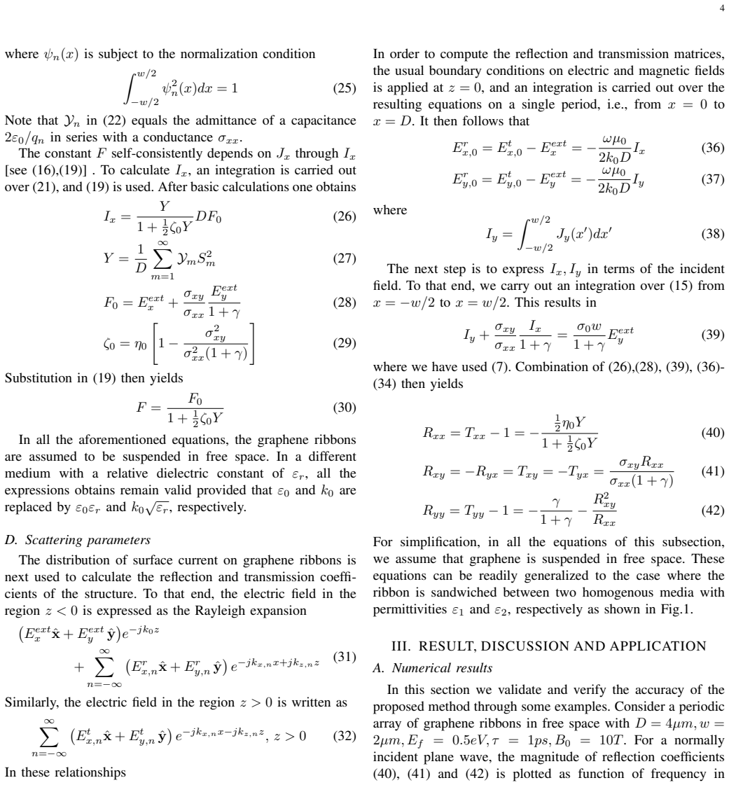
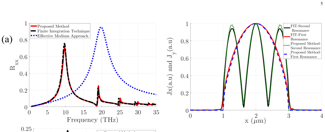
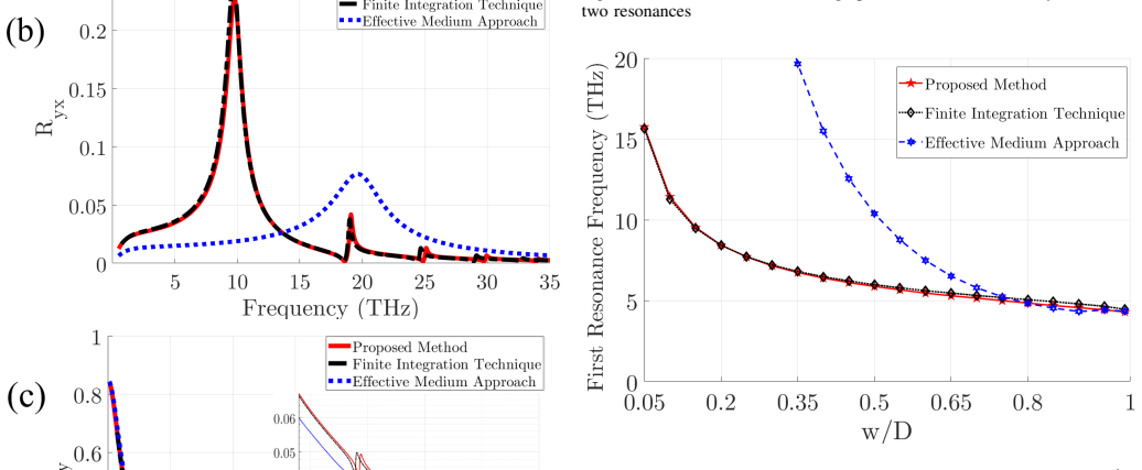
- The method predicts resonant peaks in the reflection coefficients at frequencies set by the ribbon width, arising from odd current eigenmodes $n=1,3,\ldots$, features that effective-medium theory cannot reproduce.
- The Faraday rotation angle follows from (43) and shows large values near resonance; increasing the magnetic bias increases the rotation and shifts the resonance to higher frequencies.
- The method's accuracy is bounded by the subwavelength condition $k_0D\ll 1$ and by the perturbation assumption that inter-ribbon interaction does not alter the single-ribbon eigenmodes, so accuracy degrades as frequency or fill factor rises.
Reading between the lines
- Because the final formulas are algebraic, they could be inverted: given a target Faraday rotation at a chosen terahertz frequency, one could solve for the bias field, Fermi level, or ribbon width directly rather than by parameter sweeps.
- The same perturbation structure, a constant leading term in the periodic Green's function plus single-ribbon eigenmodes, may extend to oblique incidence or to arrays on dielectric substrates, where the constant term would be modified by the substrate's response.
- The explicit resonance condition suggests an experimental test: a terahertz transmission measurement through a biased ribbon array should show a rotation peak at the predicted width-dependent frequency, which would also reveal how far the perturbation assumption holds.
Signed reviews
Editorial analysis
A structured set of objections, weighed in public.
Referee Report
Summary. The paper presents an analytical method for computing the reflection and transmission matrices and the Faraday rotation angle of a periodic array of magnetically-biased graphene ribbons under normal incidence. Starting from integral equations for the induced surface currents, the authors approximate the periodic Green's function by its constant leading term for the y-component and reduce the x-component equation to the single-ribbon eigenproblem of Ref. [31] with a modified forcing term. This yields the closed-form expressions (40)-(42) for the scattering matrices and (43) for the Faraday rotation. The results are validated against CST full-wave simulations for several parameter sets, with resonance-frequency errors from 0.5% at the first resonance to 2.71% at the fourth. The method is compared with effective-medium theory and a semi-analytical approach, demonstrating that the new closed forms capture resonant features that the earlier methods miss.
Significance. If the results hold, the paper provides a fast, parameter-free analytical tool for designing terahertz devices based on magnetically-biased graphene ribbon arrays, avoiding the computational cost of full-wave simulations and the inaccuracies of effective-medium models. The paper is honest about its limitations, explicitly stating that the perturbation solution (21) assumes that inter-ribbon interactions do not affect the eigenvalue equation (24) and that accuracy degrades with increasing fill factor. The explicit error quantification against CST is a strength, as is the clear statement of the subwavelength validity regime. The main gap is the lack of a D-sweep test, which the major comment addresses.
major comments (1)
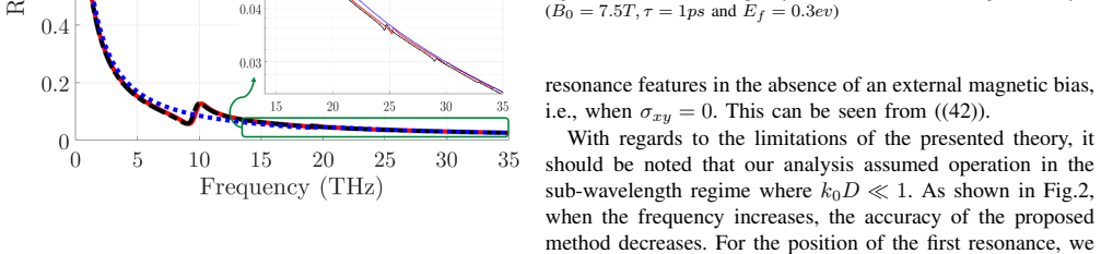
- [II.C, Eq. (24)] The eigenvalue equation (24) used in the perturbation solution (21) contains no dependence on the array period D. Since the poles of Yn in (22) are set by qn, the Rxx resonance frequencies predicted by (40) are formally independent of D for a fixed ribbon width w. This is a falsifiable prediction of the closed-form solution, but the paper's validation does not isolate it: Fig. 4 keeps D = 10 µm and varies w, so it tests the effect of the gap D - w but not the D-dependence. To support the central claim that (40)-(42) are accurate for subwavelength arrays, the authors should add a D-sweep at fixed w (e.g., w = 2 µm, D = 3-12 µm, with the same Ef, tau, and B0) and compare the resonance frequencies from (40) with CST, reporting the error as in Fig. 4. This is needed because the neglected image terms in the kernel of (18) could shift the resonances by more than the 0.5-2.71% errors seen in Fig. 2, without violating the stated k0D << 1 condition.
minor comments (4)
- [II.C, text after Eq. (20)] The perturbation solution (21) is imported from Ref. [31] without an explicit derivation or a statement of the small parameter that controls the perturbation. Please provide a brief justification or a precise reference to the relevant equations in [31] so the reader can assess the conditions under which the interaction between ribbons does not affect the eigenproblem (24).
- [III.A, Fig. 4 caption] The caption and the text should specify how the relative error in the resonance frequency is defined (e.g., |f_theory - f_FIT|/f_FIT) and for which resonance (first, n = 1) it is computed.
- [Appendix A, Eqs. (A.5)-(A.6)] The derivation of the expansion in k0D and k0|x| is compressed; please show the intermediate steps for the first integral in (A.5) to demonstrate explicitly that it is of order k0D, as claimed.
- [Throughout] There are several minor typographical issues: 'in case of normal incidence' should be 'in the case of normal incidence' (Section II.C), 'a analytical' should be 'an analytical' (Section IV), and 'in Fig.5b' should be 'in Fig. 5(b)' (Section III.B).
Circularity Check
No significant circularity: the closed-form reflection, transmission, and Faraday-rotation expressions follow from stated integral-equation approximations and are validated against external CST simulations, so self-citations do not make the derivation circular.
full rationale
The central derivation chain is not circular. The conductivity tensor (Eq. (2)) comes from an external microscopic model [27]. The array current solution (21) uses the eigenfunctions and eigenvalues of the single-ribbon integral operator from the authors' prior work [31]; this is a parameter-free published analytical result with its own independent derivation and validation, not a restatement of the paper's target quantities. The array effects enter only through the constant F and the parameter gamma, and no parameter is fitted to the CST full-wave data used for validation. The paper explicitly flags the perturbation-theory assumption that periodic-image interactions do not alter the eigenvalue equation (24), and notes that accuracy degrades as w/D increases (Sec. III.A); this is an honest validity limitation, not a circular step. Faraday rotation (43) is the standard definition from [20], evaluated with independently derived T-matrix elements. The only mild concern is the manuscript's reliance on self-citations [31] and [32] for the load-bearing eigenproblem, but because those results are externally published, parameter-free, and independently validated, they count as real evidence under the review rules. Accordingly the score is low, reflecting some self-citation but no reduction of the predictions to their inputs.
Assumptions & free parameters
assumptions (5)
- domain assumption The Drude-like conductivity tensor (2) for magnetically-biased graphene, valid for highly doped graphene with Ef >> hbar omega and Ef >> kB T.
- domain assumption Quasi-static approximation for narrow ribbons: k0 w << 1, with the Hankel Green's function replaced by the logarithmic approximation (5).
- domain assumption The periodic Green's function expansion (13) retaining only the leading constant term, valid for k0 D << 1.
- domain assumption Perturbation theory assumption that inter-ribbon interaction does not change the single-ribbon eigenvalue equation (24).
- standard math Standard electromagnetic boundary conditions and Rayleigh expansion for the fields in the homogeneous regions.
Cite this review
Pith. "Pith review of An Analytical and Rigorous Method for Analysis of an Array of Magnetically-Biased Graphene Ribbons." pith.science (2026). https://pith.science/paper/FKBDHNTV
@misc{pith2026190804571,
  author       = {Pith},
  title        = {Pith review of: An Analytical and Rigorous Method for Analysis of an Array of Magnetically-Biased Graphene Ribbons},
  year         = {2026},
  howpublished = {\url{https://pith.science/paper/FKBDHNTV}},
  note         = {Machine review of arXiv:1908.04571}
}
read the original abstract
A sheet of graphene under magnetic bias attains anisotropic surface conductivity, opening the door for realizing compact devices such as Faraday rotators, isolators and circulators. In this paper, an accurate and analytical method is proposed for a periodic array of graphene ribbons under magnetic bias. The method is based on integral equations governing the induced surface currents on the coplanar array of graphene ribbons. For subwavelength size ribbons subjected to normally incident plane waves, the current distribution is derived leading to analytical expressions for the reflection/transmission coefficients. The results obtained are in excellent agreement with full-wave simulations and predict resonant spectral effects that cannot be accounted for by existing semi-analytical methods. Finally, we extract an analytical, closed form solution for the Faraday rotation of magnetically-biased graphene ribbons. In contrast to previous studies, this paper presents a fast, precise and reliable technique for analyzing magnetically-biased array of graphene ribbons, which are one of the most popular graphene-based structures.
Figures

Figures from the paper (3 more)
Reference graph
Works this paper leans on
-
[31]
Analytical modeling of graphene ribbons as optical circuit elements,
A. Khavasi and B. Rejaei, “Analytical modeling of graphene ribbons as optical circuit elements,” IEEE Journal Of Quantum Electronics, vol. 50, no. 6, pp. 397–403, 2014
work page 2014
-
[26]
Magnetically-biased graphene-based hyperbolic metasurfaces,
J. S. Gomez-Diaz and A. Al `u, “Magnetically-biased graphene-based hyperbolic metasurfaces,” in 2016 IEEE International Symposium on Antennas and Propagation (APSURSI) . IEEE, 2016, pp. 359–360
work page 2016
-
[20]
Faraday rotation due to excitation of magnetoplasmons in graphene microribbons,
M. Tymchenko, A. Y . Nikitin, and L. Mart ´ın-Moreno, “Faraday rotation due to excitation of magnetoplasmons in graphene microribbons,” ACS nano, vol. 7, no. 11, pp. 9780–9787, 2013
work page 2013
-
[1]
A. K. Geim and K. S. Novoselov, “The rise of graphene,” in Nanoscience and Technology: A Collection of Reviews from Nature Journals . World Scientific, 2010, pp. 11–19
work page 2010
-
[2]
Electric field effect in atomically thin carbon films,
K. S. Novoselov, A. K. Geim, S. V . Morozov, D. Jiang, Y . Zhang, S. V . Dubonos, I. V . Grigorieva, and A. A. Firsov, “Electric field effect in atomically thin carbon films,” science, vol. 306, no. 5696, pp. 666–669, 2004
work page 2004
-
[3]
Superior thermal conductivity of single-layer graphene,
A. A. Balandin, S. Ghosh, W. Bao, I. Calizo, D. Teweldebrhan, F. Miao, and C. N. Lau, “Superior thermal conductivity of single-layer graphene,” Nano letters, vol. 8, no. 3, pp. 902–907, 2008
work page 2008
-
[4]
Graphene photonics, plasmonics, and broadband optoelectronic devices,
Q. Bao and K. P. Loh, “Graphene photonics, plasmonics, and broadband optoelectronic devices,” ACS nano, vol. 6, no. 5, pp. 3677–3694, 2012
work page 2012
-
[5]
Multilayer graphene-based metasurfaces: robust design method for extremely broadband, wide-angle, and polarization-insensitive terahertz absorbers,
M. Rahmanzadeh, H. Rajabalipanah, and A. Abdolali, “Multilayer graphene-based metasurfaces: robust design method for extremely broadband, wide-angle, and polarization-insensitive terahertz absorbers,” Applied optics, vol. 57, no. 4, pp. 959–968, 2018
2018
Show all 33 references
-
[6]
An informa- tion theory-inspired strategy for design of re-programmable encrypted graphene-based coding metasurfaces at terahertz frequencies,
A. Momeni, K. Rouhi, H. Rajabalipanah, and A. Abdolali, “An informa- tion theory-inspired strategy for design of re-programmable encrypted graphene-based coding metasurfaces at terahertz frequencies,” Scientific reports, vol. 8, no. 1, p. 6200, 2018
2018
-
[7]
Nanostructured graphene metasurface for tunable terahertz cloaking,
P.-Y . Chen, J. Soric, Y . R. Padooru, H. M. Bernety, A. B. Yakovlev, and A. Al `u, “Nanostructured graphene metasurface for tunable terahertz cloaking,” New Journal of Physics , vol. 15, no. 12, p. 123029, 2013
2013
-
[8]
Analytical inves- tigation of ultrabroadband plasma–graphene radar absorbing structures,
M. Rahmanzadeh, H. Rajabalipanah, and A. Abdolali, “Analytical inves- tigation of ultrabroadband plasma–graphene radar absorbing structures,” IEEE Transactions on Plasma Science , vol. 45, no. 6, pp. 945–954, 2017
2017
-
[9]
Analog computing using graphene-based metalines,
S. AbdollahRamezani, K. Arik, A. Khavasi, and Z. Kavehvash, “Analog computing using graphene-based metalines,” Optics letters , vol. 40, no. 22, pp. 5239–5242, 2015
2015
-
[10]
Design of ultra-broadband graphene absorber using circuit theory,
A. Khavasi, “Design of ultra-broadband graphene absorber using circuit theory,” JOSA B, vol. 32, no. 9, pp. 1941–1946, 2015
1941
-
[11]
Tunable graphene antennas for selective enhancement of thz-emission,
R. Filter, M. Farhat, M. Steglich, R. Alaee, C. Rockstuhl, and F. Lederer, “Tunable graphene antennas for selective enhancement of thz-emission,” Optics express, vol. 21, no. 3, pp. 3737–3745, 2013
2013
-
[12]
Multi-bit graphene-based bias-encoded metasurfaces for real-time terahertz wavefront shaping: From controllable orbital angular momentum generation toward arbitrary beam tailoring,
K. Rouhi, H. Rajabalipanah, and A. Abdolali, “Multi-bit graphene-based bias-encoded metasurfaces for real-time terahertz wavefront shaping: From controllable orbital angular momentum generation toward arbitrary beam tailoring,” Carbon, vol. 149, pp. 125–138, 2019
2019
-
[13]
Dyadic green’s functions for an anisotropic, non- local model of biased graphene,
G. W. Hanson, “Dyadic green’s functions for an anisotropic, non- local model of biased graphene,” IEEE Transactions on Antennas and Propagation, vol. 56, no. 3, pp. 747–757, 2008
2008
-
[14]
Near optimal graphene terahertz non-reciprocal isolator,
M. Tamagnone, C. Moldovan, J.-M. Poumirol, A. B. Kuzmenko, A. M. Ionescu, J. R. Mosig, and J. Perruisseau-Carrier, “Near optimal graphene terahertz non-reciprocal isolator,” Nature communications , vol. 7, p. 11216, 2016
2016
-
[15]
Non-reciprocal magneto- plasmon graphene coupler,
N. Chamanara, D. Sounas, and C. Caloz, “Non-reciprocal magneto- plasmon graphene coupler,” Optics express, vol. 21, no. 9, pp. 11 248– 11 256, 2013
2013
-
[16]
Fundamental limits and near-optimal design of graphene modulators and non-reciprocal devices,
M. Tamagnone, A. Fallahi, J. R. Mosig, and J. Perruisseau-Carrier, “Fundamental limits and near-optimal design of graphene modulators and non-reciprocal devices,” Nature photonics , vol. 8, no. 7, p. 556, 2014
2014
-
[17]
Giant faraday rotation in single-and multilayer graphene,
I. Crassee, J. Levallois, A. L. Walter, M. Ostler, A. Bostwick, E. Roten- berg, T. Seyller, D. Van Der Marel, and A. B. Kuzmenko, “Giant faraday rotation in single-and multilayer graphene,”Nature Physics, vol. 7, no. 1, p. 48, 2011
2011
-
[18]
Electrically controlled terahertz magneto-optical phenomena in continuous and patterned graphene,
J.-M. Poumirol, P. Q. Liu, T. M. Slipchenko, A. Y . Nikitin, L. Martin- Moreno, J. Faist, and A. B. Kuzmenko, “Electrically controlled terahertz magneto-optical phenomena in continuous and patterned graphene,” Nature communications, vol. 8, p. 14626, 2017
2017
-
[19]
Manipulation of giant faraday rotation in graphene metasurfaces,
A. Fallahi and J. Perruisseau-Carrier, “Manipulation of giant faraday rotation in graphene metasurfaces,” Applied Physics Letters , vol. 101, no. 23, p. 231605, 2012
2012
-
[21]
Electromagnetic nonreciprocity and gy- rotropy of graphene,
D. L. Sounas and C. Caloz, “Electromagnetic nonreciprocity and gy- rotropy of graphene,” Applied Physics Letters, vol. 98, no. 2, p. 021911, 2011
2011
-
[22]
Matrix exponential fdtd modeling of magnetized graphene sheet,
X.-H. Wang, W.-Y . Yin, and Z. Chen, “Matrix exponential fdtd modeling of magnetized graphene sheet,” IEEE Antennas and Wireless Propaga- tion Letters, vol. 12, pp. 1129–1132, 2013
2013
-
[23]
Modeling of magnetized graphene from microwave to thz range by dgtd with a scalar rbc and an ade,
P. Li and L. J. Jiang, “Modeling of magnetized graphene from microwave to thz range by dgtd with a scalar rbc and an ade,” IEEE Transactions on Antennas and Propagation , vol. 63, no. 10, pp. 4458–4467, 2015
2015
-
[24]
Analysis of magnetically biased graphene-based periodic structures using a transmission-line formulation,
P. K. Khoozani, M. Maddahali, M. Shahabadi, and A. Bakhtafrouz, “Analysis of magnetically biased graphene-based periodic structures using a transmission-line formulation,” JOSA B , vol. 33, no. 12, pp. 2566–2576, 2016
2016
-
[25]
Modeling magne- tized graphene in the finite-difference time-domain method using an anisotropic surface boundary condition,
M. Feizi, V . Nayyeri, and O. M. Ramahi, “Modeling magne- tized graphene in the finite-difference time-domain method using an anisotropic surface boundary condition,”IEEE Transactions on Antennas and Propagation, vol. 66, no. 1, pp. 233–241, 2018. 8
2018
-
[27]
Faraday effect in graphene enclosed in an optical cavity and the equation of motion method for the study of magneto-optical transport in solids,
A. Ferreira, J. Viana-Gomes, Y . V . Bludov, V . Pereira, N. Peres, and A. C. Neto, “Faraday effect in graphene enclosed in an optical cavity and the equation of motion method for the study of magneto-optical transport in solids,” Physical Review B , vol. 84, no. 23, p. 235410, 2011
2011
-
[28]
Graphene plasmonics for tunable terahertz metamaterials,
L. Ju, B. Geng, J. Horng, C. Girit, M. Martin, Z. Hao, H. A. Bechtel, X. Liang, A. Zettl, Y . R. Shen et al., “Graphene plasmonics for tunable terahertz metamaterials,” Nature nanotechnology, vol. 6, no. 10, p. 630, 2011
2011
-
[29]
Boron nitride substrates for high-quality graphene electronics,
C. R. Dean, A. F. Young, I. Meric, C. Lee, L. Wang, S. Sorgenfrei, K. Watanabe, T. Taniguchi, P. Kim, K. L. Shepard et al., “Boron nitride substrates for high-quality graphene electronics,” Nature nanotechnol- ogy, vol. 5, no. 10, p. 722, 2010
2010
-
[30]
Tai, Dyadic Green functions in electromagnetic theory
C.-T. Tai, Dyadic Green functions in electromagnetic theory . Institute of Electrical & Electronics Engineers (IEEE), 1994
1994
-
[32]
Adopting image theorem for rigorous analysis of a perfect electric conductor–backed array of graphene ribbons,
M. Rahmanzadeh, A. Abdolali, A. Khavasi, and H. Rajabalipanah, “Adopting image theorem for rigorous analysis of a perfect electric conductor–backed array of graphene ribbons,” JOSA B , vol. 35, no. 8, pp. 1836–1844, 2018
2018
-
[33]
I. S. Gradshteyn and I. M. Ryzhik, Table of integrals, series, and products. Academic press, 2014. Mahdi Rahmanzadeh was born in Amol, Iran, in 1994. He received the B.Sc. degree from the Babol Noshirvani Institute of Technology, Babol, Iran and the M.Sc. degree from the Iran ...
2014
Reviewed August 14, 2026 · model on record in the stance chip above.
Discussion (0). Continue with ORCID to comment.