REVIEW 4 major objections 5 minor 25 references
Single-layer Circular SIW Filtenna With Beam Scanning Capability for 5G Millimeter Wave Communication Applications
T0 review · 4 major / 5 minor · reviewed 2026-08-07 · deepseek-v4-flash
Pith's one-line read A single-layer printed circuit board can carry a 28 GHz filtering antenna that also scans beams, by merging two cavity modes with two metal posts.
desk verdict Genuine but incremental hardware paper: two measured single-layer circular SIW filtennas with a plausible mode-merging mechanism, though the perturbation derivation is too garbled to verify and the beam scanning is simulation-only. read the letter →
The pith
A machine-rendered reading of the paper's core claim, the machinery that carries it, and where it could break.
The reading
What carries the argument
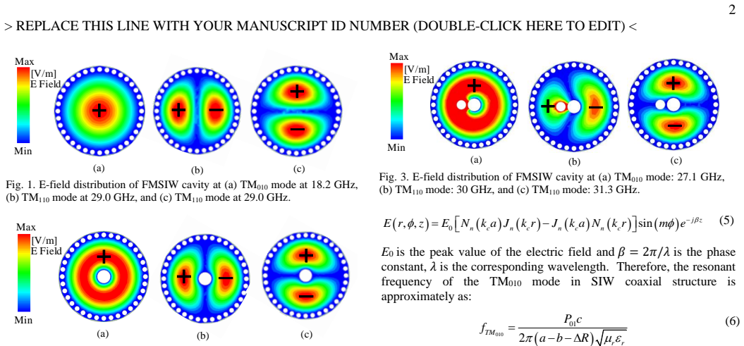
The carrying mechanism is the near-independent perturbation of the two cavity modes by two metal posts: TM010, the fundamental mode with its electric field concentrated at the cavity centre, and TM110, the next mode with an electric-field null at that point. The shift of TM010 follows from the coaxial-cavity transcendental equation with inner radius b, while the shift of TM110 comes from a cavity-perturbation integral evaluated with Bessel-function identities. The feed post uses the electric perturbation where the TM110 field is strong, pulling that mode down, and its position leaves the degenerate partner almost unchanged. The half-moon slot acts as the load in a two-path coupling matrix, with the external quality factor of each mode set by the feed-post distance; the merging creates the wide passband and the two interfering paths create the radiation nulls.
What would settle it
A clean check is to simulate the bare circular cavity, add only the centre post, and then only the feed post: the first should raise the lower resonance by about 9 GHz while barely moving the upper one, and the second should lower the upper resonance by about 1 GHz while barely moving the lower one. If both additions shift the two resonances together, the independent-perturbation premise fails; a fabrication sweep of the centre-post radius would test the predicted shifts directly.
Extended reading notes
Core claim
On the paper's own terms, the discovery is that the frequency gap between the first two transverse-magnetic modes of a circular SIW cavity is not a fixed obstacle but a tunable design variable. The centre post sits at the electric-field maximum of TM010, so it raises that mode from about 18.2 GHz to 27.4 GHz, while TM110, which has a field null at the centre, barely feels it; the feed post sits where the TM110 field is strong, so it lowers TM110 by about 1 GHz while leaving TM010 and the degenerate TM110 partner nearly in place. With the two resonances merged near 28 GHz, the half-moon slot couples both cavity modes to free space, and the two coupling paths, one through each mode, create radiation nulls in the stopband without any added filter circuit. Filtenna 1 shows three upper-band nulls and Filtenna 2 trades one null for a steeper lower roll-off. Measured prototypes confirm the merged passband, stable patterns, and sideband suppression above 18 dB.
Load-bearing premise
The design rests on the assumption that the centre post moves one cavity resonance and the feed post moves the other almost independently; if the two perturbations interfere, the modes cannot be merged into one wide passband.
Editorial extensions
If this is right
- A 1x8 array of either filtenna is simulated to scan to ±40° at 28 GHz with less than 3 dB scanning loss, and each scanned beam keeps more than 15 dB stopband suppression.
- The single-layer format removes the need for stacked filter cavities, so the filtering antenna array can be fabricated on one F4B board, cutting cost and alignment error.
- The design equations give a direct dial for fractional bandwidth: choosing the centre-post radius b and the feed-post offset sets the merged-mode spacing and hence the target x% in the paper's equation (15).
- Moving the slot from the feed side, Filtenna 1, to the opposite side, Filtenna 2, trades three upper radiation nulls for roughly 10 dB better lower-stopband roll-off.
Reading between the lines
- A testable extension is to scale the cavity radius and post sizes to other mmWave 5G bands, such as 26 GHz or 39 GHz; the scaling of the resonance formulas suggests the mode-merging recipe should transfer, but the paper does not demonstrate this.
- The two-path coupling model implies the upper radiation nulls arise from interference between the TM010 and TM110 paths; if so, adjusting the slot length or coupling signs could move individual nulls without retuning the passband, giving filter-shape control the paper does not explore.
- The simulated arrays share a row of vias between adjacent elements; building the 1x8 prototypes and measuring the per-beam filtering response would test whether the ±40° scan claim holds outside simulation.
Editorial analysis
A structured set of objections, weighed in public.
Referee Report
Summary. The paper proposes two single-layer circular substrate-integrated waveguide (SIW) filtering antennas for millimeter-wave 5G applications. The design merges the TM010 and TM110 cavity modes using a central metal post and a feeding post, and radiates through a half-moon-shaped slot. Two prototypes are fabricated and measured: Filtenna 1 achieves a measured -10 dB impedance bandwidth of 8.6% (27.62-30.11 GHz) and Filtenna 2 achieves 10.1% (28.11-31.09 GHz), with measured radiation patterns and realized gain in reasonable agreement with simulation. Beam scanning is demonstrated through simulated 1x8 arrays, claiming a scanning range of ±40 degrees with less than 3 dB scanning loss.
Significance. If the mode-merging mechanism is sound, the work would offer a compact, low-cost, single-layer filtenna element with both filtering and beam-scanning capability, which is genuinely useful for 5G mmWave arrays. The authors provide fabricated prototypes, measured S11 and radiation patterns, and a comparison table that situates the design against prior multi-layer filtennas. The central contribution, however, is the claimed independent tunability of TM010 and TM110 via the center post and the feed post; this mechanism is presented through a derivation that is currently not usable as written. The experimental results are valuable, but the paper's main claim about the design procedure needs to be made transparent and checkable.
major comments (4)
- [Section II-A, Eqs. (5)-(14)] The perturbation derivation for the TM110 mode is not usable as printed. Equation (5) is duplicated (the same number is used for the TM wave electric-field expression and later for the cavity perturbation formula), symbols Q and ΔR in Eqs. (8) and (14) are undefined, and Eq. (14) as typeset is not a well-formed expression. No numerical substitution is shown, so the claimed agreement of 31.52 GHz with a 1.35% relative error cannot be verified. This derivation is load-bearing because it is the quantitative basis for the mode-merging design procedure, and it must be corrected and made reproducible.
- [Section II-A, Fig. 2] The claim that the central post has 'more impact' on TM010 than on TM110 is quantitatively supported, but the text also implies the TM110 shift is small enough to preserve independent tunability. Figure 2 shows the TM110 resonance shifts from 29.0 GHz to 31.1 GHz after inserting the 1.1-mm-diameter post, a shift of 2.1 GHz that is comparable to the 2-2.5 GHz target passband. The derivation in Eq. (14) predicts a shifted frequency of 31.52 GHz, which is consistent with a large shift, not a small perturbation. The paper needs to reconcile this: if both modes shift substantially, the design procedure must demonstrate that the net effect still allows the two modes to be brought together in a controllable way, rather than relying on full-wave tuning.
- [Abstract, Table I, Conclusion] The reported sideband suppression levels are inconsistent across the manuscript. The abstract states both filtennas exceed 18 dB suppression; Table I lists >16 dB and >23 dB for the two designs; the Conclusion states the upper and lower sideband suppression exceeds 16 dB and 25 dB; and Section II-E states the simulated arrays have more than 15 dB stopband suppression in both sidebands. These numbers should be unified and tied to specific measured or simulated curves, because the filtering performance is a central claim.
- [Section II-E and title] The 'beam scanning capability' is demonstrated only through simulated 1x8 arrays; no array is fabricated or measured. Since the title and abstract present beam scanning as a demonstrated capability of the proposed filtennas, the paper should either clearly label the beam-scanning results as simulated only, or provide measured array results. As written, a reader could reasonably infer that the scanning performance has been experimentally validated.
minor comments (5)
- [Overall equations] Equation numbering is inconsistent: Eq. (5) is used twice, and later Eqs. (6), (7), (8) repeat numbers already assigned to earlier equations in Section II-A. The equations should be renumbered sequentially.
- [Section II-A, Eqs. (6) and (14)] The symbols ΔR and Q are used without definition. In particular, ΔR appears in Eq. (6) and Q appears in Eqs. (8) and (14); their definitions should be stated explicitly before use.
- [Figures] Several figure references are incorrect or duplicated: Fig. 3 in Section II-B is described as the feed-position case but the caption refers to the FMSIW cavity; Fig. 9 is duplicated; and Section II-D states the fabricated prototype of Filtenna II is in Fig. 12, but Fig. 12 is the Qext plot, while the photograph is in Fig. 13(a).
- [Abstract and body text] There are grammatical errors, e.g., 'the proposed filtennas consists of' and 'The filtennas features stable radiation patterns.' These should be corrected during revision.
- [Section II-C, 'full-angle filtering'] The statement that the antenna 'exhibits full-angle filtering characteristics' at 20 GHz is supported only by the maximum gain of -19.1 dBi at that frequency. It is unclear whether this gain is low at all angles; the 3D radiation pattern shown is a single view. Please clarify or soften the claim.
Circularity Check
No significant circularity: the mode-merging design is checked against HFSS eigenmode simulation and hardware measurements; the only self-citations are background formulas and prior dual-mode filtenna work.
full rationale
The load-bearing derivation chain is not circular. Section II-A computes the TM010 shift from coaxial-cavity boundary conditions and the TM110 shift from cavity perturbation theory (Eqs. (3)-(14)); the predicted shifted TM110 frequency (31.52 GHz) is explicitly compared with HFSS (31.1 GHz, 1.35% error), and both final filtennas are fabricated and measured (S11, gain, patterns, FBW 8.6% and 10.1%). Those results are externally falsifiable, not fitted parameters renamed as predictions. The paper does cite the authors' own [9] for the SIW effective-radius formula and [8] for the single-layer dual-mode filtenna concept, but these citations are background: the resonant-frequency ratio 1.5934 is independently confirmed by HFSS, and the mode-merging mechanism is supported by the paper's own eigenmode plots and perturbation calculation rather than imported from [8]. The skeptic's observation that the center post also shifts TM110 by about 2.1 GHz (Fig. 2) is a validity concern about the 'almost unchanged' approximation, not a circular reduction; the same applies to the garbled Eq. (5)/(14) numbering and undefined symbols Q and DeltaR, which are presentation/correctness issues. No self-citation chain forces the claimed FBW, suppression, or ±40-degree scanning capability, so the circularity score is low (2) only because of minor background self-citations.
Assumptions & free parameters
free parameters (5)
- Central metal post radius, r2 =
0.55 mm
- Feeding post offset from cavity center =
1.0-1.6 mm range; d3 = 1.6 mm in Fig. 4
- Half-moon slot width, w1 =
0.6 mm
- Substrate thickness, H0 =
1.0 mm
- Coupling matrix entries =
Matrix (17) for Filtenna I, matrix (18) for Filtenna II
assumptions (5)
- standard math TM-mode field solutions and transcendental equation for a coaxial circular cavity (Eqs. (4)-(5))
- domain assumption Cavity perturbation theory with a small-volume metal post (Eq. (5) in Section II-A)
- domain assumption Empirical effective-radius formula for SIW circular cavity (Eq. (2))
- standard math Coupled-resonator filter theory with external quality factor and coupling matrix (Eqs. (16)-(18))
- domain assumption Slot acts as an ideal load in the coupling topology (Fig. 5)
Cite this review
Pith. "Pith review of Single-layer Circular SIW Filtenna With Beam Scanning Capability for 5G Millimeter Wave Communication Applications." pith.science (2026). https://pith.science/paper/FPNCTQB3
@misc{pith2026250600361,
  author       = {Pith},
  title        = {Pith review of: Single-layer Circular SIW Filtenna With Beam Scanning Capability for 5G Millimeter Wave Communication Applications},
  year         = {2026},
  howpublished = {\url{https://pith.science/paper/FPNCTQB3}},
  note         = {Machine review of arXiv:2506.00361}
}
read the original abstract
In this communication, two novel low-cost single-layer filtering antennas (filtennas) are proposed for millimeter wave (mmWave) applications. The proposed filtennas consists of a compact circular substrate integrated waveguide (SIW) cavity, a metal post close to the center of the cavity for power feeding, a metal post in the center for modes controlling, and a slot for radiating power. In the passband, the fundamental TM010 mode and the TM110 mode in the circular SIW cavity are excited by the feeding post. In addition, thanks to the high-pass characteristics of the cavity, it exhibits more than 20 dB suppression in the lower frequency band. There are three radiation nulls in Filtenna 1 and one radiation null in Filtenna 2 in the upper band which increase the suppression level as high as 18 dB. As a proof of concept, the proposed filtennas are fabricated and measured. It is shown that the Filtenna 1 can achieve simulated and measured -10 dB impedance fractional bandwidth (FBW) of 7.1% (27.14 - 29.13 GHz) and 8.6% (27.62 - 30.11 GHz), respectively. While filtenna 2 can achieve simulated and measured -10 dB FBW of 7.4% (27.86 - 29.99 GHz) and 10.1% (28.11 - 31.09 GHz), respectively. The filtennas features stable radiation patterns with an average gain of 5.0 dBi. The lower and upper sideband suppression levels for both filtennas exceed 18 dB. These filtennas are good candidates for 5G mmWave applications, as they simultaneously provide beam scanning and filtering capability with a low cost, and single layer structure.
Figures

Reference graph
Works this paper leans on
-
[8]
Single -layer millimeter-wave filtenna with quasi-elliptic gain response under dual- mode resonance,
J. Li, L. Xiang, Y. Shi, X. Yu Wu and W. Hong, "Single -layer millimeter-wave filtenna with quasi-elliptic gain response under dual- mode resonance," IEEE Antennas Wireless Propag. Lett., vol. 23, no. 9, pp. 2797-2801, Sept
-
[9]
Flat gain, single-layer annular cavity filtenna based on TM and quasi-TM modes,
J. Li and H. Aliakbari, "Flat gain, single-layer annular cavity filtenna based on TM and quasi-TM modes," IEEE Antennas Wireless Propag . Lett., doi: 10.1109/LAWP.2025.3563353
-
[1]
The Role of millimeter-wave technologies in 5G/6G wireless communications,
W. Hong, et al., "The Role of millimeter-wave technologies in 5G/6G wireless communications," IEEE J. Microwaves , vol. 1, no. 1, pp. 101 - 122, Jan. 2021
work page 2021
-
[2]
Filtenna designs for radio -frequency front -end systems: A structural -oriented review,
Shome, P. P., Khan, T., Koul, S. K., & Antar, Y. M. (2020). "Filtenna designs for radio -frequency front -end systems: A structural -oriented review," IEEE Antennas Propag. Mag , vol. 63, no. 5, pp. 72 -84, Oct. 2021
work page 2020
-
[3]
https://www.3gpp.org/3gpp-groups
-
[4]
Li J, Zhu Y, Hu Y, Hong W. "Millimeter -wave filtenna for 5G application with multiple controllable radiation nulls and wide stopband". Microw. Opt. Technol. Lett. 2024
work page 2024
-
[5]
Compact Wideband patch filtenna with enhanced out-of-band suppression,
Q. Da Liu, Q. Dong, J. X. Wen, L. H. Ye, D. -L. Wu and X. Y. Zhang, "Compact Wideband patch filtenna with enhanced out-of-band suppression," IEEE Antennas Wireless Propag . Lett., vol. 22, no. 9, pp. 2310-2314, Sept. 2023
work page 2023
-
[6]
An integrated filtering antenna array with high selectivity and harmonics suppression,
C. -X. Mao et al., "An integrated filtering antenna array with high selectivity and harmonics suppression," IEEE Trans . Microw. Theory Techn., vol. 64, no. 6, pp. 1798-1805, June 2016
work page 2016
Show all 25 references
-
[7]
A wideband circularly polarized 2 × 2 filtenna array with multiple radiation nulls,
W. Wang, H. Jin, W. Yu, X. H. Zhang, K. -S. Chin and G. Q. Luo, "A wideband circularly polarized 2 × 2 filtenna array with multiple radiation nulls," IEEE Antennas Wireless Propag . Lett., vol. 21, no. 3, pp. 595-599, March 2022
2022
-
[10]
A design of bandwidth-enhanced cavity-backed slot filtenna using resonance windows,
Y. -M. Wu, S. -W. Wong, H. Wong and F. -C. Chen, "A design of bandwidth-enhanced cavity-backed slot filtenna using resonance windows," IEEE Trans . Antennas Propag ., vol. 67, no. 3, pp. 1926 - 1930, March 2019
1926
-
[11]
Compact, low- profile, bandwidth-enhanced substrate integrated waveguide filtenna,
K. -Z. Hu, M. -C. Tang, M. Li and R. W. Ziolkowski, "Compact, low- profile, bandwidth-enhanced substrate integrated waveguide filtenna," IEEE Antennas Wireless Propag . Lett., vol. 17, no. 8, pp. 1552 -1556, Aug. 2018
2018
-
[12]
Substrate -integrated-waveguide-fed wideband filtering antenna for millimeter-wave applications,
H. -T. Hu and C. H. Chan, "Substrate -integrated-waveguide-fed wideband filtering antenna for millimeter-wave applications," IEEE Trans. Antennas Propag., vol. 69, no. 12, pp. 8125-8135, Dec. 2021
2021
-
[13]
Lightweight and compact high- gain filtering aperture antenna fabricated by three-dimensional printing technology,
X. He, Y. Zhang, M. Du and J. Xu, "Lightweight and compact high- gain filtering aperture antenna fabricated by three-dimensional printing technology," IEEE Antennas Wireless Propag . Lett., vol. 17, no. 7, pp. 1141-1144, July 2018
2018
-
[14]
Novel millimeter-wave bandwidth-controllable filtering antenna based on composite ESPPs - SIW structure,
X. -F. Zhang, S. -H. Cao and J. -X. Chen, "Novel millimeter-wave bandwidth-controllable filtering antenna based on composite ESPPs - SIW structure," IEEE Trans . Antennas Propag ., vol. 69, no. 11, pp. 7924-7929, Nov. 2021
2021
-
[15]
A 3 -D millimeter-wave filtering antenna with high selectivity and low cross-polarization,
H. Chu, C. Jin, J. -X. Chen and Y. -X. Guo, "A 3 -D millimeter-wave filtering antenna with high selectivity and low cross-polarization," IEEE Trans. Antennas Propag., vol. 63, no. 5, pp. 2375-2380, May 2015
2015
-
[16]
A millimeter-wave filtering monopulse antenna array based on substrate integrated waveguide Technology,
H. Chu, J. -X. Chen, S. Luo and Y. -X. Guo, "A millimeter-wave filtering monopulse antenna array based on substrate integrated waveguide Technology," IEEE Trans. Antennas Propag., vol. 64, no. 1, pp. 316-321, Jan. 2016
2016
-
[17]
A Wideband and high-gain filtering antenna for 5G millimeter-wave applications. ,
Y. -M. Pan, G. Liu, X. -Y. Liu, K. W. Leung and P. F. Hu, "A Wideband and high-gain filtering antenna for 5G millimeter-wave applications. ," IEEE Trans . Antennas Propag ., vol. 71, no. 11, pp. 9006-9011, Nov. 2023
2023
-
[18]
SIW cavity-fed filtennas for 5G millimeter-wave applications,
R. Lu et al., "SIW cavity-fed filtennas for 5G millimeter-wave applications," IEEE Trans. Antennas Propag., vol. 69, no. 9, pp. 5269 - 5277, Sept. 2021
2021
-
[19]
Highly selective and compact filtering antennas using dual-mode SIW resonators,
M. D. Brown and C. E. Saavedra, "Highly selective and compact filtering antennas using dual-mode SIW resonators," IEEE Trans . Antennas Propag., vol. 71, no. 5, pp. 3928-3937, May 2023
2023
-
[20]
Implementation of synthetic material in dielectric resonator-based filtering antennas,
H. Chu, H. Hong, X. Zhu, P. Li and Y. -X. Guo, "Implementation of synthetic material in dielectric resonator-based filtering antennas," IEEE Trans. Antennas Propag., vol. 66, no. 7, pp. 3690-3695, July 2018
2018
-
[21]
Design of filtering dielectric resonator antenna arrays using simple feeding networks,
C. X. Zhao, Y. M. Pan , and G. D. Su, "Design of filtering dielectric resonator antenna arrays using simple feeding networks," IEEE Trans. Antennas Propag., vol. 70, no. 8, pp. 7252-7257, Aug. 2022
2022
-
[22]
Linearly and circularly polarized filtering dielectric resonator antennas,
Y. -T. Liu, K. W. Leung, J. Ren and Y. -X. Sun, "Linearly and circularly polarized filtering dielectric resonator antennas," IEEE Trans. Antennas Propag., vol. 67, no. 6, pp. 3629-3640, June 2019
2019
-
[23]
Waveguide Handbook,
N. Marcuvitz, "Waveguide Handbook," 1st ed, pp. 74 -84, New York, NY, USA: McGraw-Hill, 1951
1951
-
[24]
Table of Integrals, Series, and Products
I. S. Gradshteyn, I. M. Ryzhik, "Table of Integrals, Series, and Products", 8th ed. Amsterdam, Netherlands: Academic Press, 2014
2014
-
[25]
J. S. Hong and M. J. Lancaster, Microstrip filter for RF/ microwave applications. New York, NY, USA: Wiley, 2001. (a) (b) -90 -60 -30 0 30 60 90-10 -5 0 5 10 15 20 22 24 26 28 30 32 34 36-35 -25 -15 -5 5 15 0° 13° -13° 26° -26° 40° -40° Realized gain (dBi) Frequency (GHz) #1 #...
2001
Reviewed August 7, 2026 · model on record in the stance chip above.
Discussion (0). Continue with ORCID to comment.