REVIEW 4 major objections 3 minor 32 references
Triple-Poles Complementary Split Ring Resonator for Sensing Diabetics Glucose Levels at cm-Band
T0 review · 4 major / 3 minor · reviewed 2026-08-14 · deepseek-v4-flash
Pith's one-line read A triple-poles complementary split ring resonator senses diabetic-range glucose concentrations with higher simulated sensitivity at its harmonic resonances than single- or double-pole versions.
desk verdict Simulation-only incremental design study whose new triple-pole CSRR geometry and sensitivity table are worth a referee, but whose milli-dB claims lack a numerical noise floor and whose Table III contradicts the abstract. read the letter →
The pith
A machine-rendered reading of the paper's core claim, the machinery that carries it, and where it could break.
The reading
What carries the argument
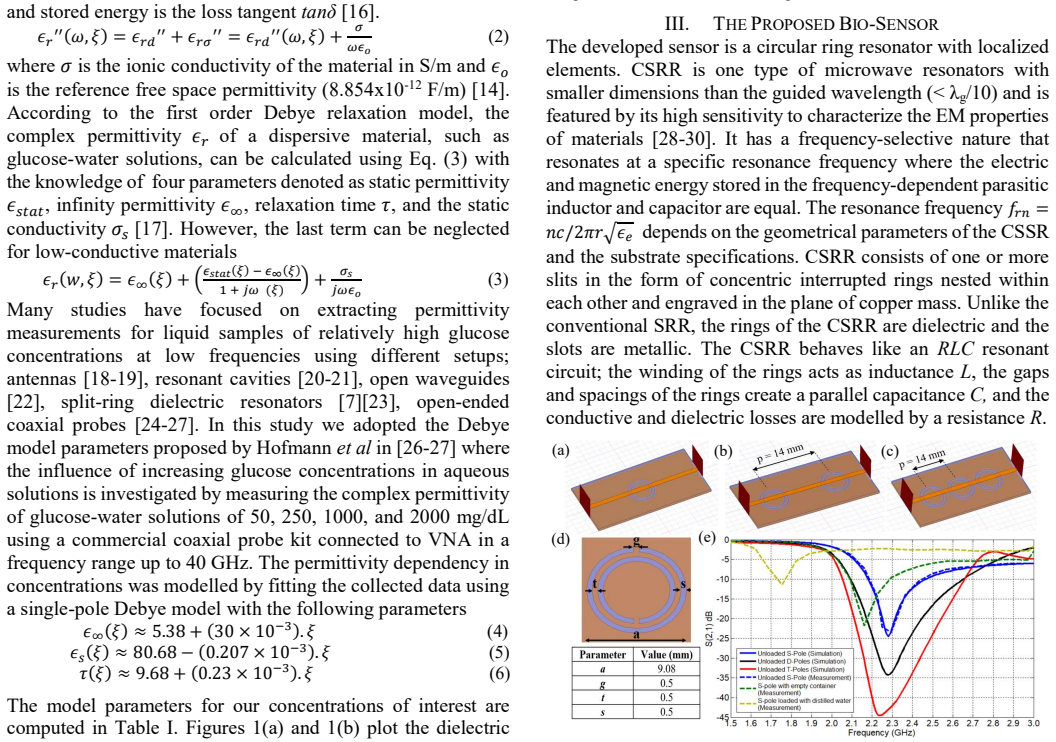
The central object is the triple-poles complementary split ring resonator (CSRR): a set of concentric split rings etched in the ground plane beneath a microstrip line, behaving as an RLC circuit whose resonance frequency depends on ring geometry and on the permittivity and loss of material placed over the slots. The load-bearing model is the single-pole Debye relaxation model of the glucose-water solution, whose concentration-dependent permittivity is computed from fitted parameters and fed into a full-wave electromagnetic simulation. The design produces three resonance poles in the 1–6 GHz band; the higher-order poles concentrate intense electric fields near the sensing region, so small changes in the glucose superstrate's loss tangent and permittivity translate into measurable changes in $S_{21}$ depth and resonance frequency. The resonance condition $f_{rn}=n c/(2\pi r\sqrt{\epsilon_e})$ ties each pole's location to the ring geometry and the effective permittivity of the loaded structure.
What would settle it
Fabricate the single-, double-, and triple-poles CSRRs and measure $S_{21}$ with a vector network analyzer while loading them with glucose-water samples at 70, 80, 90, 100, 110, and 120 mg/dL, matching the simulated glass, skin, and glucose layer geometry; the central claim is falsified if the triple-poles device does not show larger resonance-depth changes than the other two at the second or third resonance, or if the 70-to-80 mg/dL $S_{21}$ shift (claimed 0.092 dB) is indistinguishable from repeated measurements on the same sample. A second check: measure the complex permittivity of 70–120 mg/dL solutions with a calibrated probe; if it differs from Eqs. (4)–(6), the simulation inputs and the resulting sensitivity ranking are not trustworthy.
Extended reading notes
Core claim
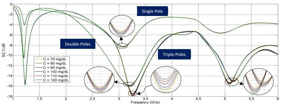
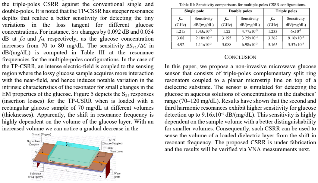
The paper's central claim is that a triple-poles complementary split ring resonator—three concentric split rings etched in the ground plane of a 50 Ω microstrip line on FR4—resonates at three frequencies in the 1–6 GHz band, and that the second and third resonances respond more strongly to glucose-induced dielectric changes than the first resonance, and more strongly than single- and double-pole versions. In the simulations, loading the sensor with glucose-water solutions from 70 to 120 mg/dL changes the transmission coefficient $S_{21}$—the amount of microwave power passing from input to output—in a concentration-dependent way; for a 70-to-80 mg/dL step, $S_{21}$ drops by 0.092 dB at the second resonance (3.262 GHz) and by 0.054 dB at the third resonance (about 5.165 GHz), giving a peak sensitivity of $9.16\times10^{-3}$ dB/(mg/dL). The response depends on sample volume: smaller loaded volumes give larger loss-related changes, and the resonance frequency shifts with the volume of the dielectric layer. The paper concludes that this CSRR design is a candidate for a non-invasive, portable glucose sensor operating in the diabetic concentration range.
Load-bearing premise
The load-bearing premise is that the standard single-pole Debye model, fitted to glucose-water measurements at 50–2000 mg/dL, still gives accurate permittivity and loss values for the 70–120 mg/dL diabetic range in the 1–6 GHz band, so the predicted tiny $S_{21}$ changes reflect real glucose-driven dielectric changes rather than model extrapolation error or numerical noise.
Editorial extensions
If this is right
- At the second and third resonances, the triple-poles CSRR should resolve 10 mg/dL glucose steps in aqueous solution, because the claimed $S_{21}$ change for a 70-to-80 mg/dL step is 0.092 dB and 0.054 dB at those frequencies.
- The same resonator can estimate the volume of a dielectric layer from the resonance-frequency shift, with sensitivity to loss increasing for smaller sample volumes.
- Because the sensor offers three resonance readouts in one device, a future monitor could cross-check glucose estimates from each pole and reject readings affected by volume or coupling changes.
- The planar FR4/microstrip construction is compatible with low-cost printed-circuit fabrication, so the sensor could be integrated into portable or wearable monitors if the simulated performance is confirmed in hardware.
- The operating band (1–6 GHz) lies within standard cm-wave components, so the interrogating electronics do not need exotic or expensive high-frequency hardware.
Reading between the lines
- Beyond the paper's full-wave simulations, the 0.092 dB signal for a 70-to-80 mg/dL step sits close to typical measurement repeatability of laboratory vector-network-analyzer setups; a practical device would likely need averaging, temperature control, or a reference resonator to make the glucose signature readable.
- If the Debye model parameters were re-fitted specifically in the 70–120 mg/dL range, the predicted sensitivity ranking across poles could change; the comparative advantage of the triple-poles design deserves re-testing with directly measured permittivity data rather than extrapolated values.
- The same multi-pole geometry could be applied to other aqueous analytes with distinct dielectric signatures, such as salinity, urea, or lactate, since the sensor responds generically to permittivity and loss-tangent changes near its resonances.
- A plausible experimental roadmap is to first verify the permittivity model with a coaxial probe, then compare single-, double-, and triple-poles CSRRs under identical loading; the second resonance at 3.262 GHz is the best place to look for the largest separation.
Signed reviews
Editorial analysis
A structured set of objections, weighed in public.
Referee Report
Summary. The manuscript proposes a triple-pole complementary split-ring resonator (CSRR) on an FR4 microstrip for microwave glucose sensing in aqueous solutions over 70-120 mg/dL. Using HFSS full-wave simulations and a single-pole Debye model with coefficients taken from Hofmann et al., the authors compare S21 responses of single-, double-, and triple-pole CSRRs at three resonances, reporting sensitivities up to 9.16x10^-3 dB/(mg/dL) and claiming higher sensitivity for the triple-pole design at the different resonances. The paper also studies the effect of sample volume on resonance frequency and depth, and concludes that the sensor can detect small dielectric variations of glucose solutions in the cm-band.
Significance. If the reported milli-dB sensitivities survive numerical and experimental scrutiny, the design would be a plausible low-cost cm-band biosensor element and the comparison across single/double/triple CSRR topologies would be a useful benchmark. The paper is transparent about its simulation-only status and about the origin of the Debye coefficients, and it provides quantitative sensitivity tables. However, the headline claim is not yet supported: the reported S21 differences are not shown to exceed numerical noise, and Table III contradicts the claim at the third resonance. These are fixable with additional convergence analysis and a tempered claim, but they are load-bearing for the central result.
major comments (4)
- [Section III, Fig. 4 and Table III] The central sensitivity comparison is based on S21 differences of 0.05-0.09 dB, but no mesh-convergence study, adaptive-refinement stopping criterion, or numerical-noise floor is reported. At resonance notches the S21 response is steep, so discretization error and frequency-sweep interpolation can easily be of the same order as the reported signal. The paper must report a mesh-convergence study (e.g., delta-S adaptive criteria, mesh density doubling) and a numerical noise floor for the S21 differences before the sensitivity ranking among single, double, and triple poles can be considered established.
- [Table III and Abstract] Table III undercuts the abstract's claim of "higher sensitivity at the different resonances." At the third resonance, the double-pole configuration shows 6.98x10^-3 dB/(mg/dL) at 5.088 GHz, whereas the triple-pole shows 5.57x10^-3 dB/(mg/dL) at 5.165 GHz. The authors should either qualify the claim to the first two resonances or provide a comparative figure of merit (for example, sensitivity normalized by quality factor or by resonance-frequency SNR) under which the triple-pole design is actually superior at all resonances.
- [Section II, Eqs. (4)-(6) and Table I] The Debye coefficients from Hofmann et al. are used for 70-120 mg/dL, which lies within the original fit range of 50-2000 mg/dL, so this is interpolation rather than extrapolation. Nonetheless, the accuracy of the single-pole Debye model at low concentrations and in the 1-6 GHz band is not validated. Because the entire sensing signal depends on tiny permittivity differences between concentrations, the paper should include a sensitivity analysis that perturbs epsilon_inf, epsilon_s, and tau by their fit uncertainties and reports the resulting variation in the computed S21 differences.
- [Section III and Conclusion] The paper explicitly states that the proposed CSRR is "under fabrication" and that results will be verified via VNA measurements "next." For a sensing paper, this means the claimed glucose detectability is an unverified simulation prediction. At minimum, the manuscript should clearly label the results as a design-prediction study and provide numerical uncertainty quantification, including the HFSS noise floor, so that the quantitative claims can be evaluated independently of the promised future measurements.
minor comments (3)
- [Table III caption] The caption reads "multiple-poles CSSR configurations" but the acronym should be CSRR; the same inconsistency appears as "TP-CSSR" elsewhere while the paper elsewhere uses TP-CSRR.
- [Fig. 5 and Table III] The zoom-in in Fig. 5 reports a sensitivity of about 0.055 dB/(mg/dL) at fr3 = 4.94 GHz for V = 0.54 mL, while Table III lists 5.57x10^-3 dB/(mg/dL) at 5.165 GHz for the triple-pole; the authors should clarify whether this is a different loading volume and explain the order-of-magnitude discrepancy.
- [Throughout] Minor grammatical issues include "due their intense interaction" and similar phrases; these should be corrected to "due to".
Circularity Check
No significant circularity: the simulated sensitivities are full-wave outputs from external Debye permittivity inputs, not fitted quantities or self-citation results.
full rationale
The paper's central claim is that the triple-poles CSRR shows higher simulated sensitivity at its resonances. The derivation chain is: external Debye-model parameters from Hofmann et al. (Eqs. 4-6 and Table I) provide permittivity values; these are loaded into HFSS; full-wave simulation solves for S21; sensitivity is then computed as ΔS21/ΔC from the simulated transmission curves. No parameter is fitted to the reported sensitivity values, and the resonator geometry is optimized for a resonance frequency (2.29 GHz), not for the sensitivity figures. Thus the S21 changes of 0.092 dB and 0.054 dB and the sensitivity of 9.16e-3 dB/(mg/dL) are not equivalent to the input permittivities by any equation; they arise from the Maxwell-solver response to the input. The Debye model itself comes from Hofmann et al., an external source, and is used as an input assumption rather than as proof of the sensor ranking. The self-citations in the paper ([9], [12], [13]) are contextual and not load-bearing: they support background patterns or general methods, not the specific sensitivity comparison. There is no imported uniqueness theorem, no ansatz smuggled in via citation, and no renaming of a known result. Concerns about numerical convergence, the milli-dB noise floor, and the fact that Table III does not actually show the triple-poles design as most sensitive at the third resonance are validation and correctness concerns, not circularity. The paper is self-contained as a simulation study with stated external material parameters, so a non-circular finding is appropriate.
Assumptions & free parameters
free parameters (3)
- Debye model coefficients from Hofmann fit =
epsilon_inf = 5.38 + 0.030*xi, epsilon_s = 80.68 - 0.207e-3*xi, tau = 9.68 + 0.23e-3*xi ps
- Resonator geometry (ring radii, widths, gaps) =
not reported
- Sample and layer thicknesses =
hglass = 0.13 mm, hskin = 0.1 mm, hglucose = 2 mm
assumptions (5)
- domain assumption Aqueous glucose solutions adequately mimic the dielectric behavior of human blood for glucose sensing at 1-6 GHz.
- domain assumption The single-pole Debye model with Hofmann's parameters is accurate for 70-120 mg/dL glucose-water solutions in the 1-6 GHz band.
- domain assumption HFSS full-wave simulations faithfully predict the physical S21 response of the fabricated sensor.
- domain assumption The skin dielectric parameters (epsilon_r' = 38.1, tan_delta = 0.28 for 0.1 mm skin) are representative of diabetic skin at these frequencies.
- standard math Maxwell's equations and the standard RLC circuit equivalence of the CSRR resonator describe the device behavior.
Cite this review
Pith. "Pith review of Triple-Poles Complementary Split Ring Resonator for Sensing Diabetics Glucose Levels at cm-Band." pith.science (2026). https://pith.science/paper/GHAIAOXI
@misc{pith2026190807407,
  author       = {Pith},
  title        = {Pith review of: Triple-Poles Complementary Split Ring Resonator for Sensing Diabetics Glucose Levels at cm-Band},
  year         = {2026},
  howpublished = {\url{https://pith.science/paper/GHAIAOXI}},
  note         = {Machine review of arXiv:1908.07407}
}
read the original abstract
Microwave sensors are very promising for sensing the blood glucose levels non-invasively for their non-ionizing nature, miniaturized sizing, and low health risks for diabetics. All these features offer the possibility for realizing a portable non-invasive glucose sensor for monitoring glucose levels in real time. In this article, we propose a triple poles complementary split ring resonator (CSRR) produced on a FR4 substrate in microstrip technology in the cm-wave band (1-6 GHz). The proposed bio-sensor can detect the small variations in the dielectric properties (relative permittivity and dielectric losses) of glucose in the blood mimicking aqueous solutions due their intense interaction with the electromagnetic field at harmonic resonances. The resonator exhibits higher sensitivity performance at the different resonances compared to the single and double-poles counterparts as demonstrated by simulations in a 3D full-wave EM solver.
Figures

Figures from the paper (2 more)

Reference graph
Works this paper leans on
-
[1]
Diabetes Atlas: Global estimates of the prevalence of diabetes for 2011 and 2030,
D. Whiting, L. Guariguata, C. Weil, J. Shaw, J. IDF, “Diabetes Atlas: Global estimates of the prevalence of diabetes for 2011 and 2030,” Diabetes Res. Clin. Pract. Dec 2011, vol. 94, no. 3, pp. 311–321
work page 2011
-
[2]
Diagnosis and classification of diabetesmellitus,
American Diabetes Association, “Diagnosis and classification of diabetesmellitus,” Diabetes Care, vol. 37, pp. S81–S90, 2014
work page 2014
-
[3]
R. Holt, C. Cockram, A. Flyvbjerg and B. Goldstein, Textbook of Diabetes, New York, NY: John Wiley & Sons, 2011
work page 2011
-
[4]
Self-monitoring of blood glucose,
Canadian Diabetes Association, “Self-monitoring of blood glucose,” Jan. 12, 2018. [Online]. Available at http://www.diabetes.ca/clinical- practiceeducation/professional-resources/selfmonitoring-of-blood glucose
2018
-
[5]
Detection of glucose variability in saline solutions from transmission and reflection measurements using V-band waveguides,
H. Cano-Garcia, P. Kosmas, I. Sotiriou, I. Papadopoulos-Kelidis, C. Parini, I. Gouzouasis, G. Palikaras, and E. Kallos, “Detection of glucose variability in saline solutions from transmission and reflection measurements using V-band waveguides,” Measurement Science and Technology, vol. 26, no. 12, pp. 125701-125710, Dec 2015
2015
-
[6]
Cunningham and J
D. Cunningham and J. Stenken, In vivo glucose sensing, Hoboken, N.J: Wiley, 2010
2010
-
[7]
Design and In Vitro Interference Test of Microwave Noninvasive Blood Glucose Monitoring Sensor,
H. Choi, J. Naylon, S. Luzio, J. Beutler, J. Birchall, C. Martin, and A. Porch, “Design and In Vitro Interference Test of Microwave Noninvasive Blood Glucose Monitoring Sensor,” IEEE Transactions on Microwave Theory and Techniques, vol. 63, no. 10, pp. 3016–3025, October 2015
work page 2015
-
[8]
P. McArthur, “Numerical analysis of open-ended coaxial line probes and its application to in-vivo dielectric measurements,” PhD thesis, King College, 1989
work page 1989
Show all 32 references
-
[9]
EM Measurements of Glucose-Aqueous Solutions
A. E. Omer, G. Shaker, S. Safavi-Naeini, and R. M. Shubair, “EM Measurements of Glucose-Aqueous Solutions”, 2019 IEEE International Symposium on Antennas and Propagation and USNC-URSI Radio Science Meeting
2019
-
[10]
Analysis of an Open-Ended Coaxial Probe with Lift-O for Nondestructive Testing,
J. Baker-Jarvis, M. D. Janezic, P. D. Domich, and R. Geyer, “Analysis of an Open-Ended Coaxial Probe with Lift-O for Nondestructive Testing,” IEEE Transactions on Instrumentation and Measurement, vol. 43, no. 5, pp. 711-718, October 1994
1994
-
[11]
On the accuracy of complex permittivity model of glucose/water solutions for non-invasive microwave blood glucose sensing,
V. Turgul and I. Kale, “On the accuracy of complex permittivity model of glucose/water solutions for non-invasive microwave blood glucose sensing,” E-Health and Bioengineering Conference (EHB), Iasi, 2015, pp. 1-4
2015
-
[12]
Microwave Resonant Sensor for Non-invasive Characterization of Biological Tissues,
M. Tlili, F. Deshours, G. Alquié, H. Kokabi, S. Hardinata, F. Koskas, “Microwave Resonant Sensor for Non-invasive Characterization of Biological Tissues,” IRBM journal, vol. 39, no 6, pp. 445-450, 2018
2018
-
[13]
Improved microwave biosensor for non-invasive dielectric characterization of biological tissues,
F. Deshours, G. Alquié, H. Kokabi, K. Rachedi, M. Tlili, S. Hardinata, F. Koskas, “Improved microwave biosensor for non-invasive dielectric characterization of biological tissues,” Microelectronics Journal, vol. 88, pp. 137-144, 2019
2019
-
[14]
Fundamentals of medicalsurgical nursing,
A. Brady, C. McCabe and M. McCann, “Fundamentals of medicalsurgical nursing,” John Wiley & Sons, 2013
2013
-
[15]
Electromagnetic properties of tissue in the optical region,
K. Yaws, D. Mixon, and W. Roach, “Electromagnetic properties of tissue in the optical region,” in Biomedical Optics (BiOS) 2007. International Society for Optics and Photonics, 2007, pp. 507–643
2007
-
[16]
Komarov, S
V. Komarov, S. Wang, and J. Tang, Permittivity and Measurements. Hoboken, NJ, USA: Wiley, 2005. [Online]. Available: http://dx.doi.org/10.1002/0471654507.eme308
2005 doi
-
[17]
P. J. W. Debye, Polar molecules. Dover Publications, 1960
1960
-
[18]
Real-time monitoring glucose by used microwave antenna apply to biosensor,
S. Wiwatwithaya, P. Phasukkit, S. Tungjitkusolmun and W. Wongtrairat, “Real-time monitoring glucose by used microwave antenna apply to biosensor,” The 4th 2011 Biomedical Engineering International Conference, Chiang Mai, 2012, pp. 135-137
2011
-
[19]
A novel approach to non-invasive blood glucose measurement based on RF transmission,
M. Hofmann, T. Fersch, R. Weigel, G. Fischer, and D. Kissinger, “A novel approach to non-invasive blood glucose measurement based on RF transmission,” MeMeA 2011 IEEE International Symposium on Medical Measurements and Applications, Bari, 2011, pp. 39-42
2011
-
[20]
Blood glucose monitoring using microwave cavity perturbation,
R. Dobson, R. Wu, and P. Callaghan, “Blood glucose monitoring using microwave cavity perturbation,” Electronics Letter, vol. 48, no. 15, pp. 905–906, 2012
2012
-
[21]
Testing glucose concentration in aqueous solution based on microwave cavity perturbation technique,
Y. Fan, X. Deng, Q. Wang and W. Wang, “Testing glucose concentration in aqueous solution based on microwave cavity perturbation technique,” 2010 3rd International Conference on Biomedical Engineering and Informatics, Yantai, 2010, pp. 1046-1049
2010
-
[22]
Non- invasive glucose monitoring using open electromagnetic waveguides,
M. Hofmann, M. Bloss, R. Weigel, G. Fischer and D. Kissinger, “Non- invasive glucose monitoring using open electromagnetic waveguides,” 2012 42nd European Microwave Conference, Amsterdam, 2012, pp. 546- 549
2012
-
[23]
Microwave dielectric resonator biosensor for aqueous glucose solution,
J. Kim et al., “Microwave dielectric resonator biosensor for aqueous glucose solution,” Review of Scientific Instruments, vol. 79, no. 8, August 2008
2008
-
[24]
Cole-Cole model for glucose-dependent dielectric properties of blood plasma for continuous glucose monitoring,
T. Karacolak, E. C. Moreland, and E. Topsakal, “Cole-Cole model for glucose-dependent dielectric properties of blood plasma for continuous glucose monitoring,” Microwave and Optical Technology Letters. vol. 55, no.5, pp. 1160–1164, May 2013
2013
-
[25]
On the accuracy of complex permittivity model of glucose/water solutions for non-invasive microwave blood glucose sensing,
V. Turgul and I. Kale, “On the accuracy of complex permittivity model of glucose/water solutions for non-invasive microwave blood glucose sensing,” 2015 E-Health and Bioengineering Conference (EHB), Iasi, 2015, pp. 1-4
2015
-
[26]
Microwave-Based Noninvasive Concentration Measurements for Biomedical Applications,
M. Hofmann, G. Fischer, R. Weigel and D. Kissinger, “Microwave-Based Noninvasive Concentration Measurements for Biomedical Applications,” in IEEE Transactions on Microwave Theory and Techniques, vol. 61, no. 5, pp. 2195-2204, May 2013
2013
-
[27]
A microwave sensing system for aqueous concentration measurements based on a microwave reflectometer,
M. Hofmann, F. Trenz, R. Weigel, G. Fischer and D. Kissinger, “A microwave sensing system for aqueous concentration measurements based on a microwave reflectometer,” 2012 IEEE/MTT-S International Microwave Symposium Digest, Montreal, QC, 2012, pp. 1-3
2012
-
[28]
Complementary Split-Ring Resonators for Measuring Dielectric Constants and Loss Tangents,
C. Lee and C. Yang, “Complementary Split-Ring Resonators for Measuring Dielectric Constants and Loss Tangents,” in IEEE Microwave and Wireless Components Letters, vol. 24, no. 8, pp. 563-565, Aug. 2014
2014
-
[29]
Material Characterization Using Complementary Split-Ring Resonators,
M. S. Boybay and O. M. Ramahi, “Material Characterization Using Complementary Split-Ring Resonators,” in IEEE Transactions on Instrumentation and Measurement, vol. 61, no. 11, pp. 3039-3046, Nov. 2012
2012
-
[30]
Dual- mode behavior of the complementary electric-LC resonators loaded on transmission line: Analysis and applications,
A. Ebrahimi, W. Withayachumnankul, S. F. Al-Sarawi, D. Abbott, “Dual- mode behavior of the complementary electric-LC resonators loaded on transmission line: Analysis and applications,” Journal of Applied Physics, vol. 116, no.8, 083705, 2014
2014
-
[31]
Dielectric properties of human tissues
Institute of Applied Physics, “Dielectric properties of human tissues”,
-
[2014]
Available at: http://niremf.ifac.cnr.it
[Online]. Available at: http://niremf.ifac.cnr.it
Reviewed August 14, 2026 · model on record in the stance chip above.
Discussion (0). Continue with ORCID to comment.