REVIEW 4 major objections 4 minor 33 references
Resonant Inductive Coupling Power Transfer for Mid-Sized Inspection Robot
T0 review · 4 major / 4 minor · reviewed 2026-08-12 · deepseek-v4-flash
Pith's one-line read A resonant inductive coupling system transmits 109.7 W over 1 meter through obstacles, reaching 47.14% system efficiency and charging two 12 V, 0.8 Ah lead-acid batteries in 5 minutes.
desk verdict Battery charging claim is internally inconsistent and the efficiency measurement is underdocumented, but the WPT demonstration itself is a plausible engineering data point that deserves a serious referee. read the letter →
The pith
A machine-rendered reading of the paper's core claim, the machinery that carries it, and where it could break.
The reading
What carries the argument
The load-bearing object is the octagonal resonant coil pair: two five-turn Litz-wire coils on 1-meter octagonal frames, each coil weighing 320 g, with 1 nF compensation capacitors tuning both resonators to 615 kHz. The mechanism is resonant inductive coupling, in which the coupled Z-matrix simplifies at resonance and the received power and efficiency become $P_{R_L} = \frac{(\omega M)^2 V_p^2 R_L}{(R_p(R_s+R_L)+(\omega M)^2)^2}$ and $\eta = \frac{(\omega M)^2 R_L}{(R_s+R_L)(R_p(R_s+R_L)+(\omega M)^2)}$. In this design the key choices are the 1-meter aperture matched to the robot's scale, five turns as the simulation-determined optimum balancing resistance and coupling, 1 cm gaps between turns to reduce proximity effects, and octagonal frames chosen because simulation gave 81.22% ideal efficiency versus 80.07% for circular.
What would settle it
Put a calibrated wattmeter between the 43 V DC supply and the evaluation board, run the receiver into a 10 Ω load at 1 m with the same concrete obstacle, and compare the measured input power to the 109.7 W received; if the ratio differs from 47% by more than a few points, the headline efficiency is not supported.
Extended reading notes
Core claim
The paper claims that a five-turn octagonal Litz-wire coil pair with a 1-meter opening, compensated by 1 nF capacitors on both sides and operated at 615 kHz, transfers 109.7 W to a 10 Ω load over a 1-meter separation through a 600 mm concrete pillar and through a fire door and metal bin, with 47.14% system efficiency. In the authors' analysis this is the maximum-power-point condition, where efficiency of 50% is expected and the capacitor voltage rating is fully used; their measured value is just below that point. The same setup charges two series-connected 12 V, 0.8 Ah lead-acid batteries in 5 minutes. Simulation with the octagonal geometry predicted about 101.6 W and roughly 81% efficiency in the ideal no-obstacle case, which is the design target the hardware then approached under real conditions.
Load-bearing premise
The headline efficiency rests on an input-power measurement that the paper never documents; the only stated supply values (43 V, 7.284 A peak current) are not enough to verify the 47.14% figure.
Editorial extensions
If this is right
- A 100 W inspection robot can be charged or powered while separated from its supply by 1 m of air, concrete, or metal obstacles, removing the need to return to a docking station for every recharge.
- Operating at the 50% maximum-power-transfer point means the system trades efficiency for delivered power and full use of component ratings; a deployment that needs higher efficiency would have to move coils closer or change compensation.
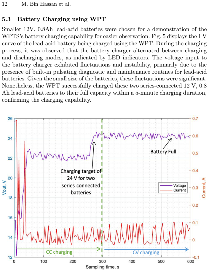
- The 5-minute charge of two 12 V, 0.8 Ah lead-acid batteries shows the power level is sufficient for small-format robot batteries, even through a charging circuit that alternates between charging and diagnostic modes.
- The offset measurements imply that coaxial alignment matters; the receiver coil must stay near the transmitter axis for the 100 W target, so robot positioning during charging will need to be controlled.
Reading between the lines
- A reader checking the arithmetic will notice that 43 V times the stated 7.284 A peak input current is about 313 W, which would put efficiency near 35%, not 47%; the paper does not show the input-power measurement behind its efficiency, so a calibrated wattmeter test would settle which figure is right.
- The near-field magnetic link should tunnel through most non-metallic building materials because the coupling is inductive; concrete walls and fire doors are tested here, but wet or reinforced concrete, steel mesh, and other conductive barriers would need their own loss measurements.
- If the coil frame were made collapsible as the authors propose as future work, the same 1-meter resonant design could apply to larger robots, while smaller robots would need a scaled aperture, which would change the mutual inductance and the efficiency balance.
- The battery charging demonstration uses lead-acid cells because their pulsating diagnostic charging is easy to observe; the same 109 W link should be tested against lithium-polymer or lithium-ion chemistries, whose charge profiles are more sensitive to voltage ripple.
Editorial analysis
A structured set of objections, weighed in public.
Referee Report
Summary. The paper presents a resonant inductive wireless power transfer system for a mid-sized inspection robot, targeting 100 W over 1 m with a 50% efficiency objective at the maximum power transfer point. A pair of octagonal Litz-wire coils with 1 m aperture, five turns each, and 1 nF compensation capacitors is designed with IPTVisual simulation and experimentally evaluated at 615 kHz. The authors report 109.7 W delivered to a 10 Ω load at 47.14% system efficiency across a 1 m gap containing a 600 mm concrete pillar or metallic obstacles, and they report charging two series-connected 12 V, 0.8 Ah lead-acid batteries to full capacity in 5 minutes. The paper also includes analytical expressions for circuit impedance, secondary current, output power, efficiency, and inductance, plus experimental results for translational offsets.
Significance. If the reported figures are correct, the demonstration of 109.7 W over 1 m through concrete and metallic obstacles with a 47.14% efficiency is a useful engineering data point for mid-range WPT in mobile robot charging. The output-power measurement is transparent and reproducible: 33.12 V across a 10 Ω load gives 109.7 W by Ohm's law, and the 50% efficiency target is openly tied to the maximum-power-transfer condition rather than to an inflated efficiency claim. The design workflow, including simulation-based selection of five coil turns to reach the 100 W target, is a normal engineering procedure and not circular. The main value of the paper is therefore experimental feasibility evidence, not a new theoretical result. However, the significance is limited by the absence of uncertainty analysis and by serious inconsistencies in two central claims, as detailed below.
major comments (4)
- [§5.3 and Abstract] The battery-charging claim is internally inconsistent with the reported output power. Two series-connected 12 V, 0.8 Ah lead-acid batteries store 2 × 12 V × 0.8 Ah = 19.2 Wh. Charging them from empty to full in 5 minutes requires an average power of 19.2 Wh / (5/60 h) = 230.4 W at the battery terminals, more than twice the reported 109.7 W output, before accounting for rectifier, DC-DC converter, and battery-charger losses. The energy delivered at 109.7 W in 5 minutes is only 9.14 Wh, which is consistent with a single 12 V, 0.8 Ah battery at 100% conversion efficiency, suggesting a factor-of-two error. The paper must report the initial state of charge, the actual energy delivered to the batteries, and the charging curve; without this, the abstract claim of full capacity in 5 minutes is physically impossible from the paper's own numbers.
- [§5.1 and Table 2] The headline efficiency of 47.14% is not verifiable from the reported data. The paper gives the DC supply voltage (43 V) and a 'peak input current' (7.284 A), but it never documents how input power was measured or computed. A peak current alone is insufficient: the average or RMS input power depends on the waveform and power factor. If the input power was inferred from a scope trace or an assumed waveform rather than a calibrated wattmeter, the efficiency could be substantially different. The authors should specify the measurement instrument, the exact quantity recorded (average DC power, RMS AC power, or fundamental-component power), and the uncertainty. They should also provide repeated-trial statistics or error bars, since the output power, efficiency, and charging time are presented as single-point measurements.
- [Eq. (2)] The coupling coefficient formula as printed is dimensionally wrong. The manuscript states k = M_p / (L_p L_s), but the coupling coefficient is dimensionless and is defined as k = M / sqrt(L_p L_s). The printed form has dimensions of 1/henry (or is undefined if M_p denotes a different quantity), and no definition of M_p is given. This is not a purely cosmetic typo because the equation is presented as the way to obtain the coupling coefficient from measured self- and mutual inductances, and the experimental section relies on such quantities. Please correct the equation and verify that any dependent derivations use the corrected form.
- [Eq. (12)] The Neumann formula for mutual inductance is garbled. The denominator '| r dli · rdlj |' is not a meaningful expression; the standard formula is M_ij = (μ0/4π) ∮∮ (dl_i · dl_j) / |r_i - r_j|, where the denominator is the scalar distance between infinitesimal segments. As printed, Eq. (12) cannot be evaluated and the discussion of self-inductance in the i = j case is consequently unclear. This should be corrected, and the relationship between Eq. (12) and Eq. (13) should be stated precisely.
minor comments (4)
- [§5.1] The sentence 'The input power was half of the output transmitted at the receiver' is ambiguous or backwards as written; it should be clarified whether the intended meaning is that the receiver power is half the input power, or something else.
- [§4, Experiments 1 and 2] The two obstacle experiments are described only qualitatively ('without significant power losses'); the paper should give a table or plot showing transmitted power and efficiency for the concrete-wall and metallic-obstacle cases, including a comparison with the unobstructed case.
- [§5.2, Fig. 4] The translational-offset results are reported as single measurements at discrete positions. Adding a short description of how the offset was measured and whether multiple trials were repeated would strengthen the comparison with the coaxial case.
- [Eq. (13) and Table 2] The self-inductance formula in Eq. (13) has unbalanced parentheses in the printed text, and the units of the term 'l/4 + ρ' are not dimensionally consistent with the preceding logarithm argument; please check the formula against a standard reference. Also, Table 2 lists Lp = 63.15 µH and Ls = 65.73 µH but the text states Lp = Ls at resonance; this discrepancy should be explained.
Circularity Check
No significant circularity: the headline power/efficiency results are experimental measurements, the coil design is optimized against an explicit 100 W target, and the self-citations are not load-bearing.
full rationale
I walked the derivation chain from the circuit model (Eqs. 1-11), through the IPTVisual simulation selecting coil geometry and turn count, to the measured output power and efficiency. Equations (10) and (11) are standard RIPT relations and are not fitted to the headline result. The simulation was used to choose a coil design that meets the stated 100 W objective (105.7 W circular, 101.6 W octagonal), and the experiment then reports 109.7 W; this is design-to-specification, not a fitted quantity presented as a prediction. The 47.14% efficiency is reported as a measured result from the load voltage and input quantities, not constructed to equal the 50% maximum-power-transfer target. The self-citations ([1], Cheah/Watson/Lennox, for mobile-robot WPT limitations; [27], Wang/Zhang/Hui, for the IPTVisual simulation tool) supply background and a simulation tool, not the paper's central claims, and no uniqueness theorem is imported from the authors' prior work. The serious issues in the paper are correctness/consistency problems, not circularity: Eq. (2) drops the square root in the coupling-coefficient definition, the sentence 'The input power was half of the output transmitted at the receiver' is internally inconsistent with an efficiency below 100%, and the 5-minute full-charge claim for two series-connected 12 V, 0.8 Ah batteries (19.2 Wh total) at 109.7 W output is energy-inconsistent unless the batteries started substantially charged. These concerns do not amount to a circular derivation.
Assumptions & free parameters
free parameters (5)
- Number of coil turns N =
5
- Compensation capacitance Cp and Cs =
1 nF
- DC supply voltage V_DC =
43 V
- Load resistance RL =
10 ohm
- Coil aperture and inter-turn gap =
1 m aperture, 1 cm gap
assumptions (5)
- standard math Sinusoidal steady-state lumped-element RIPT circuit model (Eqs. 4-11)
- standard math Neumann's formula for mutual and self inductance (Eq. 12)
- domain assumption Litz wire and 1 cm turn gaps reduce proximity and eddy losses to the reported level
- domain assumption Concrete and metallic obstacles do not detune the resonance or shield the field significantly
- ad hoc to paper The two 12 V, 0.8 Ah lead-acid batteries are fully charged by the 5-minute WPT session
Cite this review
Pith. "Pith review of Resonant Inductive Coupling Power Transfer for Mid-Sized Inspection Robot." pith.science (2026). https://pith.science/paper/GINZYVKL
@misc{pith2026241117505,
  author       = {Pith},
  title        = {Pith review of: Resonant Inductive Coupling Power Transfer for Mid-Sized Inspection Robot},
  year         = {2026},
  howpublished = {\url{https://pith.science/paper/GINZYVKL}},
  note         = {Machine review of arXiv:2411.17505}
}
read the original abstract
This paper presents a wireless power transfer (WPT) for a mid-sized inspection mobile robot. The objective is to transmit 100 W of power over 1 meter of distance, achieved through lightweight Litz wire coils weighing 320 g held together with a coil structure of 3.54 kg. The Wireless Power Transfer System (WPTS) is mounted onto an unmanned ground vehicle (UGV). The study addresses an investigation of coil design, accounting for misalignment and tolerance issues in resonance-coupled coils. In experimental validation, the system effectively transmits 109.7 W of power over a 1-meter distance, with obstacles present. This achievement yields a system efficiency of 47.14%, a value that is remarkably close to the maximum power transfer point (50%) when the WPTS utilises the full voltage allowance of the capacitor. The paper shows the WPTS charging speed of 5 minutes for 12 V, 0.8 Ah lead acid batteries.
Figures


Figures from the paper (2 more)

Reference graph
Works this paper leans on
- [1]
- [2]
-
[3]
B. Li, Y. Zhu, Z. Wang, C. Li, Z. Peng, and L. Ge, Use of multi-rotor unmanned aerial vehicles for radioactive source search, Remote Sensing, 10(5):728, 2018
work page 2018
-
[4]
D.T. Connor, P.G. Martin, N.T. Smith, L. Payne, C. Hutson, O.D. Payton, Y. Yamashiki, and TB Scott, Application of airborne photogrammetry for the visuali- sation and assessment of contamination migration arising from a Fukushima waste storage facility, Environmental pollution, 234:610–619, 2018
work page 2018
-
[5]
M. Nancekievill, A.R. Jones, M.J. Joyce, B. Lennox, S. Watson, J. Katakura, K. Okumura, S. Kamada, M. Katoh, and K Nishimura, Development of a radiological characterization submersible rov for use at Fukushima Daiichi, IEEE Transactions on Nuclear Science, 65(9):2565–2572, 2018
work page 2018
-
[6]
C. Meurer, J.F. Fuentes-P´ erez, N. Palomeras, M. Carreras, M. Kruusmaa, Differ- ential pressure sensor speedometer for autonomous underwater vehicle velocity es- timation, IEEE Journal of Oceanic Engineering, 45(3):946–978, 2019
work page 2019
-
[7]
B. Bird, A. Griffiths, H. Martin, E. Codres, J. Jones, A. Stancu, B. Lennox, S. Watson, and X. Poteau, Radiological monitoring of nuclear facilities :Using the continuous autonomous radiation monitoring assistance robot, IEEE Robotics and Automation Magazine, 26(1):35–43, 2018
work page 2018
-
[8]
C. West, W. Cheah, V. Rajasekaran, A. West, F. Arvin, S. Watson, M. Giuliani, R. Stolkin, and B. Lennox, Development of a debris clearance vehicle for limited access environments, Poster Papers, page20, 2019
work page 2019
Show all 33 references
-
[9]
C. West, F. Arvin, W. Cheah, A. West, S. Watson, M. Giuliani, and B. Lennox, A debris clearance robot for extreme environments, In Annual Conference Towards Autonomous Robotic Systems, pages 148–159. Springer, 2019
2019
-
[10]
C. Park, S. Lee, G.H. Cho, S.Y. Choi, and C.T. Rim, Two-dimensional inductive power transfer system for mobile robots using evenly displaced multiple pickups, IEEE Transactions on Industry Applications, 50(1):558–565, 2013
2013
-
[11]
L. Xie, Y. Shi, Y. Thomas Hou, and A. Lou, Wireless power transfer and applica- tions to sensor networks, IEEE Wireless Communications, 20(4):140–145, 2013
2013
-
[12]
Choi, B.W
S.Y. Choi, B.W. Gu, S.Y. Jeong, and C.T. Rim, Advances in wireless power trans- fer systems for roadway-powered electric vehicles, IEEE Journal of emerging and selected topics in power electronics, 3(1):18–36, 2014. 14 M. Bin Hassan et al
2014
-
[13]
Shinohara, Wireless power transfer via radiowaves
N. Shinohara, Wireless power transfer via radiowaves. John Wiley and Sons, 2014
2014
-
[14]
Becker DE, Chiang R, Keys CC, Lyjak A W, Nees JA and Starch MD (2010) Photovoltaic-concentrator based power beaming for space eleva- tor application, in AIP Conference Proceedings, 271–281
2010
-
[15]
Ortabasi U and Friedman H (2006) A photovoltaic cavity converter for wireless power transmission using high power lasers, IEEE 4th World Conference on Photo- voltaic Energy Conference, Waikoloa, HI, USA
2006
-
[16]
Dickinson RM (1975) Evaluation of a Microwave High-Power Reception- Conver- sion Array for Wireless Power Transmission, Technical Report
1975
-
[17]
IEEE Antennas and Wireless Propagation Letters 17, 538–542
Wan S and Huang K (2018) Methods for improving the transmission- conversion efficiency from transmitting antenna to rectenna array in microwave power trans- mission. IEEE Antennas and Wireless Propagation Letters 17, 538–542
2018
-
[18]
IEEE Transactions on Power Electronics 30, 6011–6014
Lu F, Zhang H, Hofmann H and Mi C (2015) A double-sided LCLC-compensated capacitive power transfer system for electric vehicle charging. IEEE Transactions on Power Electronics 30, 6011–6014
2015
-
[19]
IEEE Transactions on Industrial Electronics 63, 3158–3167
Choi BH, Thai VX, Lee ES, Kim JH and Rim CT (2016) Dipole-coil-based wide- range inductive power transfer systems for wire- less sensors. IEEE Transactions on Industrial Electronics 63, 3158–3167
2016
-
[20]
IET Circuits, Devices & Systems 13, 399–405
Bati A, Luk PC, Aldhaher S, See CH, Abd-Alhameed RA and Excell PS (2019) Dynamic analysis model of a class E2 converter for low power wireless charging links. IET Circuits, Devices & Systems 13, 399–405
2019
-
[21]
Chen WX and Chen ZP (2018) Optimization on the Transmission Distance and Ef- ficiency of Magnetic Resonant WPT System, CSAA/ IET International Conference on Aircraft Utility Systems, Guiyang, China, 148–154
2018
-
[22]
Akuzawa Y, Tsuji K, Matsumori H, Ito Y, Ezoe T and Sakai K (2015) A 95% efficient inverter with 300-W power output for 6.78 MHz magnetic resonant wireless power transfer system, IEEE MTT-S International Microwave Symposium (IMS), Phoenix, AZ, USA
2015
-
[23]
Haihong, Research on microwave wireless power transmission technology in aerospace, Space Electron, Technol, 10(05):590–594, 2014
M. Haihong, Research on microwave wireless power transmission technology in aerospace, Space Electron, Technol, 10(05):590–594, 2014
2014
-
[24]
Zhang, H
Z. Zhang, H. Pang, A. Georgiadis, C. Cecati, Wireless power transfer—an overview. IEEE Transactions on Industrial Electronics, 66(2):1044–1058, 2019
2019
-
[25]
IEEE Std
IEEE Standard for Safety Levels With Respect to Human Exposure to Radio Frequency Electromagnetic Fields, 3 kHz to 300 GHz. IEEE Std. C95.1-2005, page 27, Oct. 2000
2005
-
[26]
Imura, T. (2020). Basic Circuit for Magnetic Resonance Coupling (S–S Type). In: Wireless Power Transfer. Springer, Singapore. https://doi.org/10.1007/978-981-15- 4580-1 4
2020 doi
-
[27]
H. Wang, C. Zhang, and S.Y.R. Hui, Visualization of Energy Flow in Wireless Power Transfer Systems, 2019 IEEE Wireless Power Transfer Conference (WPTC), 2019, pp. 536-541, doi: 10.1109/WPTC45513.2019.9055544
2019
-
[28]
Ruehli, Equivalent Circuit Models for Three-Dimensional Multiconductor Systems, IEEE Transactions on Microwave Theory and Techniques, vol
A.E. Ruehli, Equivalent Circuit Models for Three-Dimensional Multiconductor Systems, IEEE Transactions on Microwave Theory and Techniques, vol. MTT-22, pp. 216-221, 1974
1974
-
[29]
Rosa and L
E.B. Rosa and L. Cohen, Formulae and Tables for the Calculation of Mutual and Self-inductance, Bulletin of the Bureau of Standards, vol. 5, pp. 35-50, 1907
1907
-
[30]
Mecke, C
R. Mecke, C. Rathge, W. Fischer, and B. Andonovski, Analysis of inductive energy transmission systems with large air gap at high frequencies European Conference on Power Electronics and Applications, 2003, Toulouse. Resonant Inductive Coupling Power Transfer for Mid-Sized Insp...
2003
-
[31]
Kuyvenhoven, C
N. Kuyvenhoven, C. Dean, J. Melton, J. Schwannecke, A. Umenei, Development of a foreign object detection and analysis method for wireless power systems, In Proceedings of the IEEE Symposium on Product Compliance Engineering (PSES), San Diego, CA, USA, 10–12 October 2011; pp. 1–6
2011
-
[32]
Hui, Planar wireless charging technology for portable electronic products and qi
S. Hui, Planar wireless charging technology for portable electronic products and qi. Proc. IEEE 2013, 101, 1290–1301
2013
-
[33]
M. Fu, T. Zhang, X. Zhu, P. C. -K. Luk and C. Ma, ”Compensa- tion of Cross Coupling in Multiple-Receiver Wireless Power Transfer Sys- tems,” in IEEE Transactions on Industrial Informatics, vol. 12, no. 2, pp. 474-482, April 2016, doi: 10.1109/TII.2016.2516906. keywords: Re- ce...
2016
Reviewed August 12, 2026 · model on record in the stance chip above.
Discussion (0). Continue with ORCID to comment.