REVIEW 2 major objections 5 minor 36 references
Role of poloidal-pressure-asymmetry-driven flows in L-H transition and impurity transport during MGI shutdowns
T0 review · 2 major / 5 minor · reviewed 2026-08-14 · deepseek-v4-flash
Pith's one-line read The paper claims that a poloidal pressure asymmetry near the tokamak edge drives shear flows and a radial electric field, with the direction set by whether the asymmetry is above or below the midplane—and this up-down dependence explains…
desk verdict A clean geometric torque mechanism and new diverted-geometry simulations make a plausible case that poloidal pressure asymmetries drive edge flows, but both headline applications hinge on an asymmetry-survival premise the paper defers, so it reads as a strong mechanisms paper rather than a confirmed explanation. read the letter →
The pith
A machine-rendered reading of the paper's core claim, the machinery that carries it, and where it could break.
The reading
What carries the argument
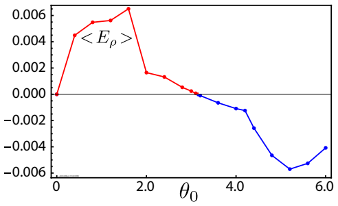
The load-bearing mechanism is the poloidal torque $\langle T_\zeta\rangle_s$ exerted by a pressure perturbation in toroidal geometry, together with the equilibrium-flow representation $\mathbf{u}=(\Phi(\psi)/\rho_m)\mathbf{B}+\Omega(\psi)R^2\nabla\zeta$. For a wrapped-Gaussian bump $\delta p(\psi,\theta)$ centered at $\theta_0$, the flux-surface-averaged torque is approximately sinusoidal in $\theta_0$ (Eq. 12): positive $\delta p$ below the midplane gives positive (counter-clockwise) poloidal flow, and above the midplane gives negative flow, independent of the direction of the toroidal field and current. This torque is balanced by viscous stress and magnetic-pumping damping in a time-dependent relaxation calculation that holds the perturbation fixed and lets the flow reach a quasi-steady state. The dependence of the torque on the sign of $\delta p$ is what turns the same geometric mechanism into an explanation of both fueling-driven flows and massive-gas-injection flows.
What would settle it
Run the same configuration with the pressure bump free to evolve instead of held stationary: if the bump is wiped out or displaced before the shear layer forms, the equilibrium picture fails. In a balanced double-null discharge with no other symmetry-breaking, inject gas at a poloidally localized point above the midplane and measure the poloidal rotation and radial electric field at the separatrix: the model demands negative poloidal flow and a positive $E_\rho$ for $\delta p>0$; seeing the opposite sign or nothing would refute it.
Extended reading notes
Core claim
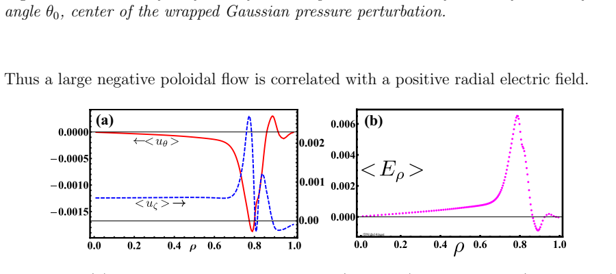
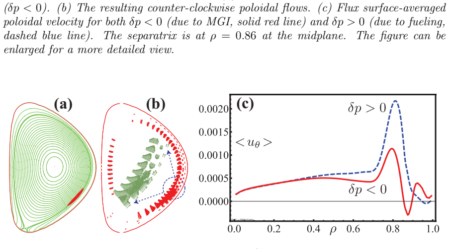
The paper's central discovery is that the location of a poloidal pressure asymmetry relative to the midplane, rather than its inboard-outboard character, controls the sign of the flows and radial electric field it generates. In toroidal geometry a localized pressure perturbation produces a net poloidal torque whose surface average is approximately proportional to $\sin\theta_0$, the poloidal location of the bump center (Eq. 12); thus a positive perturbation above the midplane drives clockwise (negative) poloidal flow and a positive $E_\rho$ just inside the separatrix, while a positive perturbation below the midplane drives counter-clockwise flow and a negative $E_\rho$ well. The calculations, carried out by relaxing a perturbed equilibrium with a time-dependent MHD code that includes viscous stress and magnetic-pumping damping, show the resulting flows are localized around the separatrix and strongly sheared. In a lower single-null with the standard field direction, the naturally expected positive asymmetry near the lower X-point therefore deepens the edge electric-field well and lowers the L-H threshold, whereas in an upper single-null the same asymmetry erodes the well and raises the threshold, giving the ordering $P_{\rm LSN}<P_{\rm DN}<P_{\rm USN}$. For massive gas injection the perturbation is a negative 'pressure hole,' so the flows reverse: upper-half-plane injection produces the counter-clockwise impurity radiation flow seen in experiments, and lower injection produces a stagnation region or downward motion, with the direction insensitive to toroidal-field reversal. With assumed edge parameters the authors estimate poloidal speeds of order $5~\mathrm{km\,s^{-1}}$ and radial fields of order $10$--$30~\mathrm{kV\,m^{-1}}$.
Load-bearing premise
The pressure asymmetry is prescribed and held fixed while the plasma relaxes; the paper does not model how the driven flows modify the asymmetry. If the flows erode or advect the bump before a quasi-steady shear layer forms, the predicted flows, electric field, and application-level conclusions would not persist.
Editorial extensions
If this is right
- In the standard field configuration, a positive pressure asymmetry near the lower X-point deepens the negative edge electric-field well and lowers the L-H transition power threshold relative to a symmetric equilibrium.
- The threshold ordering across magnetic topologies is $P_{\rm LSN}<P_{\rm DN}<P_{\rm USN}$; reversing the toroidal field reverses the ordering because the poloidal flow direction is unchanged while $E_\rho$ changes sign.
- Massive gas injection from an upper outboard location drives the impurity radiation pattern counter-clockwise across the top of the machine, while lower-location injection produces a stagnation point or downward motion, consistent with the observed flows and independent of toroidal field direction.
- A fueling port above the midplane that creates a positive edge pressure asymmetry would increase the input power needed for H-mode; ports near the X-point would be favorable.
- Deliberate placement of a poloidal pressure asymmetry can be used as an edge-control actuator to enhance or suppress confinement.
Reading between the lines
- An extension the paper leaves implicit is the back-reaction: because the calculation holds $\delta p$ fixed, whether the predicted shear layer survives in a real plasma depends on whether the flows it drives erode or advect the asymmetry; a time-dependent run with $\delta p$ free to evolve would settle this.
- The same geometric torque should apply to any poloidally localized pressure perturbation, including turbulent filaments or blobs, so edge turbulence could self-generate sheared flows whose sign is set by the perturbation's position relative to the midplane.
- The torque's linearity in the perturbation amplitude (Eq. 12) suggests a practical control criterion: the injection amplitude needed to shift the L-H threshold by a target amount could be estimated from the equilibrium response for a given device.
Signed reviews
Editorial analysis
A structured set of objections, weighed in public.
Referee Report
Summary. This paper argues that a poloidally localized pressure perturbation at the tokamak edge, whether maintained by fueling or created by radiative cooling during massive gas injection, drives poloidal and toroidal flows and a radial electric field through a purely geometric MHD torque. The analytic torque expression (Eq. 12) and CTD equilibrium computations in double-null and lower-single-null geometries are used to establish sign rules: the flow direction depends on whether the asymmetry is above or below the midplane, while the sign of the radial electric field also depends on the magnetic-field direction. The mechanism is then applied to explain the L-H power-threshold ordering PLSN < PDN < PUSN in the standard field configuration and the poloidal flow patterns observed after MGI from upper versus lower injection sites. The paper is explicitly qualitative, and it concludes with a recommendation about ITER fueling-port placement.
Significance. If the mechanism holds, the paper provides a simple, parameter-light explanation for several otherwise unexplained edge observations. The central torque derivation is transparent, and the numerical results in Figs. 2-6 consistently realize the predicted sign rules. The L-H ordering of Eq. (15) is a genuine, falsifiable prediction that is not fitted to data, and the MGI sign argument is an elegant consistency check. The paper does not supply machine-checked proofs or code, but the analytic-to-numeric chain is internally coherent. The main value is conceptual: it identifies midplane location, not merely inboard-outboard asymmetry, as the controlling parameter for edge flows.
major comments (2)
- [Section 5, Figs. 9-10] The MGI application rests on the assumption that the pressure hole with δp < 0 is held fixed while the flow equilibrates. The text states this twice: 'these are equilibrium calculations in which we seek a quasi steady-state with flows in the presence of a prescribed poloidal asymmetry that is held stationary' and 'the effect of the flows on the pressure asymmetry is not calculated here and left for a future work.' This is a load-bearing assumption because the quoted poloidal velocities (~5 km/s) are large enough to advect or erode the pressure hole during the millisecond radiative collapse, and the bolometric observations are explicitly dynamical. As written, the comparison with Fig. 8 is a kinematic consistency check, not a self-consistent prediction. I recommend either adding a time-dependent calculation, even a reduced model, or substantially reframing the MGI section so that the open self-consistency question is stated and the abstract's claim to 'explain' the MGI flows is softened.
- [Section 4, Eq. (14) and Fig. 7] The ordering PLSN < PDN < PUSN in Eq. (15) is obtained by combining the computed sign of ⟨Eρ⟩δp with an assumed linear relation between input power and edge electric field, plus a critical-field criterion for the L-H transition. The paper acknowledges the lack of a quantitative L-H theory, but the ordering is still presented as a principal result. The prediction depends on monotonicity of the power-to-electric-field response and on the absence of hysteresis or bifurcation effects; a nonlinear or non-monotonic relationship could alter the ordering. The authors should explicitly label Eq. (15) as conditional on these assumptions and briefly discuss how the conclusion changes if the linear relation is relaxed.
minor comments (5)
- [Section 1, first paragraph] The sentence beginning 'In his work we assume' should read 'In this work we assume.'
- [Figures 3-6] The captions state that velocities and electric fields are normalized, but the normalization constants (presumably the poloidal Alfvén speed vAp and E0 = ε vAp Bζ0 from Section 6) are not defined near the figures. Please state these definitions in the captions.
- [Section 6] The phrase 'somewhat larger than physical estimates' for γp and μ is vague. Since these coefficients directly control the quasi-steady flow amplitudes, please quantify the physical estimates and state clearly that the quoted dimensional values are order-of-magnitude illustrations, not quantitative predictions.
- [Abstract and Section 6] The statement about ITER fueling ports being 'misplaced' is stronger than the evidence presented, because it requires the fueling to penetrate the edge and create a positive pressure asymmetry of sufficient magnitude. I suggest phrasing this as a conditional implication rather than a definite recommendation.
- [Eq. (13)] The sign convention for Eρ = -uθBζ + uζBθ should be stated explicitly with respect to the flux-coordinate angles used in the paper, since the sign of the reported electric-field peaks depends on this convention.
Circularity Check
No circularity: the pressure-asymmetry is an externally prescribed input, and the L-H and MGI conclusions follow from computed signs of the driven flows and fields, not from fitting those conclusions.
full rationale
The derivation chain is a forward equilibrium calculation. The paper prescribes a poloidal pressure perturbation (Eq. 9), computes the geometric torque (Eqs. 10-12), and then solves the momentum equation (Eqs. 4-5) with CTD to obtain the resulting flows and radial electric field; the L-H power-threshold ordering PLSN<PDN<PUSN (Eq. 15) and the MGI poloidal-flow directions follow from the computed signs of ⟨Eρ⟩δp and uθ. No observed PLH value or MGI flow direction is used to set a free parameter, and no derived quantity is defined in terms of the target conclusion. The torque formula (Eq. 12) is cited from the author's earlier work [22], but it is displayed explicitly and is a parameter-free geometric integral, so under the evidence rules this is independent support rather than a circular load. The paper's own caveat in Section 5—'these are equilibrium calculations in which we seek a quasi steady-state with flows in the presence of a prescribed poloidal asymmetry that is held stationary. Thus, the effect of the flows on the pressure asymmetry is not calculated here and left for a future work'—is a real limitation for the transient MGI application: because the observed bolometric flows develop during a millisecond radiative collapse, the fixed-δp equilibrium may not represent the time-dependent dynamics. But that is a premise-validity concern, not a circular reduction; the flow directions are not asserted to be equivalent to the prescribed asymmetry by construction, and the paper explicitly separates the torque/flow calculation from the not-yet-modeled feedback of flows on δp. The assumed linear Pin–⟨Eρ⟩ relation in Section 4 is an acknowledged modeling assumption used to convert computed Eρ signs into threshold ordering; it is not a fitted parameter that makes the ordering tautological. Therefore no circular step is exhibited, and the appropriate finding is no significant circularity.
Assumptions & free parameters
free parameters (4)
- Pressure perturbation amplitude delta_p/p0 =
~1e-4 (normalized)
- Poloidal damping rate gamma_p =
1e-4 normalized (~5e2 s^-1 dimensional)
- Viscosity coefficient mu =
5.0e-6 normalized (=25 m^2/s)
- Gaussian width w of the pressure perturbation =
not specified (w << 2*pi)
assumptions (6)
- domain assumption Isothermal equation of state with T = T(psi)
- ad hoc to paper The poloidal pressure asymmetry is prescribed and held stationary
- ad hoc to paper Linear relation between input power and edge electric field, plus a critical E_r for L-H transition
- domain assumption Sign of delta_p: positive for fueling, negative for MGI
- standard math Axisymmetric MHD equilibrium flow form (Eq. 3)
- domain assumption Equation 12 torque formula derived in circular geometry applies to diverted configurations
Cite this review
Pith. "Pith review of Role of poloidal-pressure-asymmetry-driven flows in L-H transition and impurity transport during MGI shutdowns." pith.science (2026). https://pith.science/paper/GVKNCXTM
@misc{pith2026190801936,
  author       = {Pith},
  title        = {Pith review of: Role of poloidal-pressure-asymmetry-driven flows in L-H transition and impurity transport during MGI shutdowns},
  year         = {2026},
  howpublished = {\url{https://pith.science/paper/GVKNCXTM}},
  note         = {Machine review of arXiv:1908.01936}
}
abstract
Poloidal asymmetries in tokamaks are usually investigated in the context of various transport processes, usually invoking neoclassical physics. A simpler approach based on magnetohydrodynamics (MHD), focusing on the effects rather than the causes of asymmetries, yields useful insights into the generation of shear flows and radial electric field. The crucial point to recognize is that an MHD equilibrium in which the plasma pressure is not a flux function can be maintained only by contributions from mass flows. Coupling between the asymmetry-generated forces and toroidal geometry results in a strongly up-down asymmetric effect, where the flows exhibit a strong dependence on the location of the asymmetry with respect to the midplane. This location-dependence can be used as an effective control mechanism for the edge and thus the global confinement in tokamaks. It can also explain a number of poorly-understood observations. For instance, strong dependence of the low to high (L-H) confinement transition power threshold $P_{LH}$ on the magnetic topology can be qualitatively explained within this framework. Similarly, upper-lower midplane dependence of the poloidal flow direction after massive gas injections (MGI) naturally follows from this discussion. Similar arguments suggest that the ITER fueling ports above the midplane, to the extent they can generate a positive pressure asymmetry at the edge, are misplaced and may lead to higher input power requirements.
Figures

Figures from the paper (8 more)



Reference graph
Works this paper leans on
-
[1]
T. E. Evans. Plasma Phys. Control. Fusion , 57:123001, 2015
work page 2015
-
[2]
Y. In, J.-K. Park, Y.M. Jeon, J. Kim, G.Y. Park, J.-W. Ahn, A. Loarte, W.H. Ko, H.H. Lee, J.W. Yoo, J.W. Juhn, S.W. Yoon, H. Park, and 3D Physics Task Force in KSTAR. Enhanced understanding of non-axisymmetric intrinsic and controlled field impacts in tokamaks. Nucl. Fusion, 57:116054, 2017
work page 2017
- [3]
-
[4]
M. Groth, G. D. Porter, T. D. Rognlien, S. Wiesen, M. Wischmeier, M. N. A. Beurskens, X. Bonnin, B. D. Bray, S. Brezinsek, N. H. Brooks, et al. Poloidal distribution of recycling sources and core plasma fueling in DIII-D, ASDEX-Upgrade and JET L-mode plasmas. Plasma Phys. Cont. Fusion, 53:124017, 2011
work page 2011
-
[5]
B. A. Carreras, L. W. Owen, R. Maingi, P. K. Mioduszewski, T. N. Carlstrom, and R. J. Groebner. Phys. Plasmas , 5:2623, 1998
work page 1998
-
[6]
L.R. Baylor, P.B. Parks, T.C. Jernigan, J.B. Caughman, S.K. Combs, C.R. Foust, W.A. Houlberg, S. Maruyama, and D.A. Rasmussen. Pellet fuelling and control of burning plasmas in iter. Nucl. Fusion, 47:443, 2007
work page 2007
-
[7]
T. E. Stringer. Phys. Rev. Lett. , 22:770, 1969
work page 1969
- [8]
Show all 36 references
-
[9]
A. B. Hassam, T. M. Antonsen, J. F. Drake, and C. S. Liu. Phys. Rev. Lett. , 66:309, 1991
1991
-
[10]
A. B. Hassam and J. F. Drake. Phys. Fluids B. , 5:4022, 1993
1993
-
[11]
The effect of asymmetric gas puffing on toroidal flow in the edge of tokamak plasma
Raghvendra Singh, Andre Rogister, and Predhiman Kaw. The effect of asymmetric gas puffing on toroidal flow in the edge of tokamak plasma. Phys. Plasmas , 11:129, 2004
2004
-
[12]
K. C. Shaing and E. C. Crume. Phys. Rev. Lett. , 63:2369, 1989
1989
-
[13]
T. S. Hahm and K. H. Burrell. Phys. Plasmas , 2:1648, 1995
1995
-
[14]
Bondeson and D
A. Bondeson and D. J. Ward. Phys. Rev. Lett. , 72:2709, 1994
1994
-
[15]
Fitzpatrick and A
R. Fitzpatrick and A. Y. Aydemir. Stabilization of the resistive shell mode in tokamaks. Nucl. Fusion, 36:11, 1996
1996
-
[16]
V. D. Pustovitov. Rotation and plasma stability in the Fitzpatrick-Aydemir model. Phys. Plasmas, 14:082506, 2007
2007
-
[17]
Zehrfeld and B.J
H.P. Zehrfeld and B.J. Green. Stationary toroidal equilibria at finite beta. Nucl. Fusion, 12:569, 1972. 16
1972
-
[18]
E. Hameiri. Phys. Fluids , 26:230, 1983
1983
-
[19]
Guazzotto, R
L. Guazzotto, R. Betti, J. Manickam, and S. Kaye. Numerical study of tokamak equilibria with arbitrary flow. Phys. Plasmas , 11:604, 2004
2004
-
[20]
K. C. Shaing, R. D. Hazeltine, and H. Sanuki. Phys. Fluids B , 4:404, 1992
1992
-
[21]
J. Seol, K. C. Shaing, and A. Y. Aydemir. Physics of Plasmas , 23:042501, 2016
2016
-
[22]
A. Y. Aydemir. Effect of poloidal density asymmetries on shear flows and radial electric field at the plasma edge. Phys. Plasmas , 25:050702, 2018. arXiv:1802.06169v1 [physics.plasm-ph]
2018 arXiv
-
[23]
Hassam and Russell M
Adil B. Hassam and Russell M. Kulsrud. Phys. Fluids , 21:2271, 1978
1978
-
[24]
K. C. Shaing, K. Ida, and S. A. Sabbagh. Neoclassical plasma viscosity and transport processes in non-axisymmetric tori. Nucl. Fusion, 55:125001, 2015
2015
-
[25]
A. Y. Aydemir, J. Y. Kim, B. H. Park, and J. Seol. On resistive magnetohydrodynamic studies of sawtooth oscillations in tokamaks. Phys. Plasmas , 22:032304, 2015
2015
-
[26]
H. R. Strauss. Poloidal rotation spin-up in divertor tokamaks. Phys. Plasmas , 2:1229, 1995
1995
-
[27]
A. Y. Aydemir. Shear flows at the tokamak edge and their interaction with edge-localized modes. Phys. Plasmas , 14:056118, 2007
2007
-
[28]
A. Y. Aydemir. Shear flows at the tokamak edge and their role in core rotation and the L-H transition. Phys. Rev. Lett. , 98:225002, 2007
2007
-
[29]
J. E. Rice, W. D. Lee, E. S. Marmar, N. P. Basse, P. T. Bonoli, M. J. Greenwald, A. E. Hubbard, J. W. Hughes, I. H. Hutchinson, A. Ince-Cushman, J. H. Irby, Y. Lin, D. Mossessian, J. A. Snipes, S. M. Wolfe, S. J. Wukitch, and K. Zhurovich. Toroidal rotation and momentum transp...
2004
-
[30]
I. F. Savarkar. Private communication, 2018
2018
-
[31]
A. Y. Aydemir. Nucl. Fusion, 52:063026, 2012
2012
-
[32]
K. H. Burrell, T. N. Carlstrom, E. J. Doyle, P. Gohil, R. J. Groebner, T. Lehecka, N. C. Luhmann, Jr., H. Matsumoto, T. H. Osborne, and W. A. Peebles. Physics of the L to H transition in the DIII-D tokamak. Phys. Fluids B , 2:1405, 1990
1990
-
[33]
Ryter and the H-mode Database Working Group
F. Ryter and the H-mode Database Working Group. Nucl. Fusion, 36:1217, 1996
1996
-
[34]
E. M. Hollmann, P. B. Aleynikov, T. Fulop, D. A. Humphreys, V. A. Izzo, M. Lehnen, V. E. Lukash, G. Papp, G. Pautasso, F. Saint-Laurent, and J. A. Snipes. Status of research toward the ITER disruption mitigation system. Phys. Plasmas , 22:021802, 2015
2015
-
[35]
N. W. Eidietis, V. A. Izzo, N. Commaux, E. M. Hollmann, and D. Shiraki. Poloidal radiation asymmetries during disruption mitigation by massive gas injection on the diii-d tokamak. Phys. Plasmas, 24:102504, 2017
2017
-
[36]
E. M. Hollmann, N. Commaux, N. W. Eidietis, D. A. Humphreys, T. J. Jernigan, C. J. Lasnier, R. A. Moyer, R. A. Pitts, M. Sugihara, E. J. Strait, J. Watkins, and J. C. Wesley. Characterization of heat loads from mitigated and unmitigated vertical displacement events in diii-d. ...
2013
Reviewed August 14, 2026 · model on record in the stance chip above.
Discussion (0). Continue with ORCID to comment.