REVIEW 2 major objections 5 minor 23 references
A 4-Element MIMO Baseband Receiver with >35dB 80MHz Spatial Interference Cancellation
T0 review · 2 major / 5 minor · reviewed 2026-08-14 · deepseek-v4-flash
Pith's one-line read A 4-element baseband receiver cancels wideband spatial interference by more than 35 dB over an 80 MHz modulated bandwidth, a 592x bandwidth improvement over prior spatial cancellers.
desk verdict Measured >35 dB cancellation over 80 MHz in a 4-element baseband MIMO receiver is real, but the missing mismatch budget keeps the headline from applying to real arrays without qualification. read the letter →
The pith
A machine-rendered reading of the paper's core claim, the machinery that carries it, and where it could break.
The reading
What carries the argument
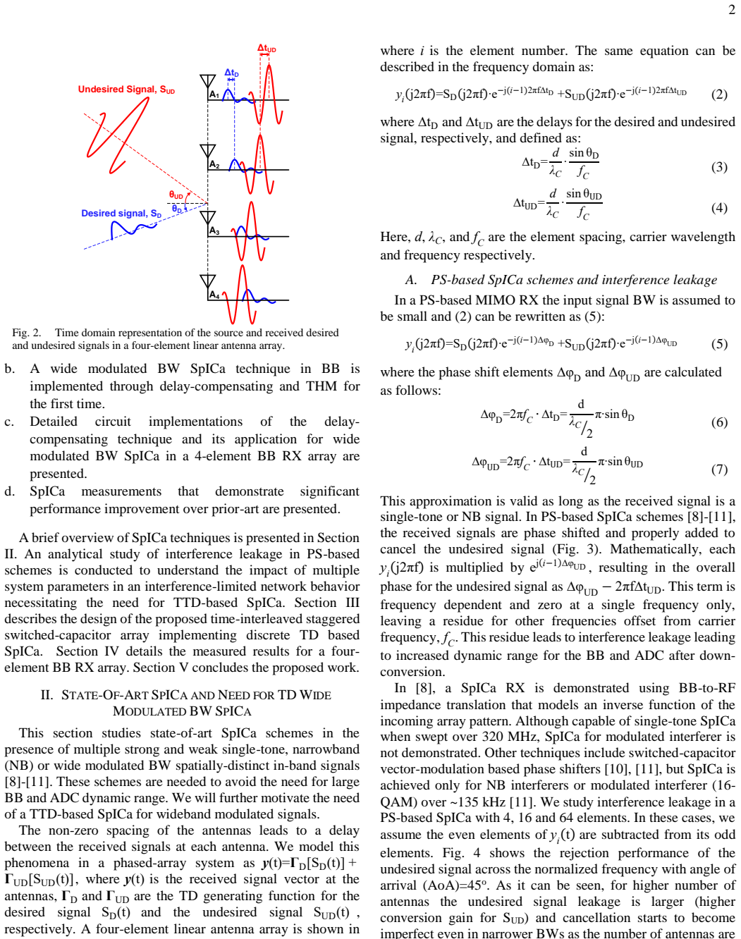
The load-bearing mechanism is the non-uniform sampling equivalence: sampling a signal with a time-delayed clock is equivalent to sampling the time-delayed version of that signal with the same clock. This lets a digitally programmable time-interleaver (15 ns total range, 5 ps steps, built from quadrature phase generation plus 8-bit phase interpolators) align the interference replicas at baseband. The aligned signals then pass through a 4×3 truncated Hadamard matrix—a matrix whose entries are only +1 and −1, realized by swapping differential input polarities and summing charges on capacitors—so cancellation occurs before summation and the summer sees mainly the weaker desired signal.
What would settle it
Inject a controlled 0.5 dB amplitude mismatch or 2 degrees phase mismatch between two of the four baseband paths in the same test setup and measure the 80 MHz modulated cancellation; if the null drops below the claimed 35 dB, the identical-replica delay model is the limiting factor and the headline number depends on idealized inputs.
Extended reading notes
Core claim
The paper's central claim is that spatially distinct in-band interference can be removed uniformly across a wide modulated bandwidth by first compensating the inter-element propagation delay at baseband, then applying a differential orthogonal combining matrix. Measured output shows more than 35 dB cancellation over an 80 MHz modulated band, with swept single-tone cancellation of 46–51 dB across 1–99 MHz that is independent of angle of arrival. The same matrix leaves the desired signal with a known, angle-dependent frequency profile that a digital equalizer can invert, so the architecture cancels the interferer before the ADC rather than requiring the ADC to digitize through it.
Load-bearing premise
Every antenna is assumed to receive the same interference signal at the same amplitude with a known inter-element delay that the circuit compensates to 5 ps accuracy; real arrays add gain mismatch, phase mismatch, mutual coupling, and multipath that the paper does not budget quantitatively.
Editorial extensions
If this is right
- A radio equipped with this baseband can place an 80 MHz spatial null instead of a single-frequency null, so a co-channel interferer from an adjacent sector does not desensitize the receiver across the whole modulated band.
- The ADC dynamic range requirement is reduced by nearly 6 bits, and since thermal-noise-limited ADC power scales roughly 4x per bit, the power saving can be substantial.
- The delay-compensation approach scales to larger arrays and wider bandwidths in principle: the interleaving level grows with array size, and the binary matrix keeps the analog multiply-accumulate simple.
- Digital equalization of the desired signal's known frequency-dependent gain is required after cancellation, and the paper shows it restores a 4 Mb/s QPSK signal with 11.5% EVM while a 12 dB stronger modulated interferer is present.
Reading between the lines
- A stress test the paper does not run is to measure cancellation with controlled gain and phase mismatch between elements; because Eq. (1) assumes identical-amplitude delayed replicas, a small mismatch budget would show how much of the 35 dB is left in a realistic array.
- The same non-uniform-sampling plus binary orthogonal-matrix structure could be extended to cancel two spatially distinct interferers simultaneously, which the paper notes but does not demonstrate with two independent delay settings.
- Since BB delay plus LO phase shift is mathematically equivalent to RF true time delay, the architecture could be pushed to wider fractional bandwidths by increasing the sampling clock; the reported clocking power scales with the clock frequency, so that trade-off is testable.
Signed reviews
Editorial analysis
A structured set of objections, weighed in public.
Referee Report
Summary. The manuscript presents a 4-element MIMO baseband receiver that cancels a wide-modulation-bandwidth spatial interferer by first time-aligning the interferer replicas with a discrete-time delay (5 ps resolution, 15 ns range) and then applying a truncated Hadamard transform (THM) with antipodal binary coefficients. The analytical section derives the residual of phase-shift-only cancellation, gives the desired-signal conversion gains for the proposed THM in Eqs. (8)-(10), and motivates the true-time-delay approach. Section III describes the time-interleaver and switched-capacitor MAC implementation, and Section IV reports measured single-tone cancellation >46 dB across 1-99 MHz, modulated cancellation >35 dB over 80 MHz, a QPSK EVM of 11.5% with a 12 dB stronger interferer, and a total analog-plus-clock power of 52 mW. A comparison table contrasts the result with prior spatial-cancellation work.
Significance. If the measured claims hold, the work is a worthwhile demonstration: it shows uniform wideband nulling at baseband with simple binary coefficients, and the >35 dB over 80 MHz is substantially wider than prior modulated-bandwidth cancellation demonstrations, with a plausible 6-bit reduction in ADC dynamic-range requirement. The analytical derivation in Section II is internally consistent and does not rely on fitted constants; the circuit implementation is described in enough detail to be reproduced; and the measurement setup and comparison table are clearly presented. The main reservations concern robustness to non-ideal array impairments rather than the internal correctness of the derivation.
major comments (2)
- [II-B, IV, Eq. (1)] The cancellation claim is built on the equal-amplitude delayed-replica model in Eq. (1). For a 35 dB null the residual must be below 1.78% of the interferer amplitude. For the first THM row [1,-1,1,-1], independent per-element gain errors with rms σ produce a residual with rms 2σ, so σ must be below roughly 0.9% for 35 dB cancellation. Section II-B acknowledges amplitude/phase mismatch only qualitatively and refers to digital calibration, but no mismatch budget, calibration coefficient precision, or measured element-to-element matching is reported. The test setup in Fig. 15 feeds all four inputs from AWGs with equal amplitudes and exactly known delays, so the headline measurement does not exercise this dominant real-world impairment. Please add a quantitative sensitivity analysis linking mismatch magnitude to cancellation depth, and ideally a measurement with deliberately introduced mismatch or with calibrated gain correction.
- [IV, Fig. 18] The >35 dB modulated-bandwidth cancellation result is presented as a single trace with no repeated measurements, no chip-to-chip variation, and no explicit statement about whether the plotted cancellation is limited by the measurement noise floor. Since the central claim is a measured number, the paper should report at least a repeatability statement for the cancellation measurement and should indicate the noise floor relative to the cancellation floor in Fig. 18.
minor comments (5)
- [Abstract, IV] The '592x improvement' is a ratio of demonstrated modulated bandwidths (80 MHz versus 135 kHz), not a ratio of cancellation depths; please state this explicitly to avoid implying a directly comparable performance metric.
- [III-A] The sentence 'an 8-bit-binary is capable of 5 ps resolution (=1.25 ns/256)' is incomplete and grammatically unclear; please revise to state that the 8-bit phase interpolator provides 5 ps resolution over a 1.25 ns interpolation range.
- [IV, Table I] The proposed-work P1dB is given as 4.73 dBm in Table I and 4.7 dBm in the text; please unify the notation.
- [I-IV] The term 'spatial' could be scoped more precisely: the testbed generates the spatial scenario as predetermined baseband delays, so antenna mutual coupling, LNA gain/phase mismatch, and RF front-end frequency responses are outside the demonstrated measurement. A sentence in Section IV clarifying this scope would be helpful.
- [II-C, Fig. 6] The paper mentions that the desired-signal frequency-dependent profile 'can be equalized after digitization,' but does not discuss noise enhancement from equalization near spectral nulls of the conversion gains in Eq. (10); a brief note on equalizer design or SNR impact would strengthen the practical claim.
Circularity Check
No significant circularity: the cancellation claim is a measured external result, and the only self-citation is disclosed, non-load-bearing prior hardware work.
full rationale
The paper's derivation chain is self-contained. The signal model in Eq. (1) is a stated assumption about element delays, and the transfer functions in Section II-C, especially Eq. (10), follow algebraically from applying the truncated Hadamard matrix to the delayed-signal vector in Eq. (9); no fitted constants or measured data are used to produce these expressions. The headline claim of greater than 35 dB cancellation over 80 MHz is an external measurement on a fabricated 65 nm CMOS prototype, not a prediction of the model, so it cannot be circular by construction. The only self-citation is [15], the authors' prior delay-compensating technique, which is disclosed as prior hardware and supplies the delay-generation mechanism rather than the cancellation result; the cancellation claim is supported by the measurements in Section IV and by comparison to prior art, not by the self-citation. The THM itself is attributed to an external reference [16]. The acknowledged amplitude/phase mismatch concern in Section II-B is a robustness or correctness limitation, not a circularity: the paper does not fit a parameter and then rename it as a prediction. Overall, no load-bearing step reduces to its own inputs, so the circularity score is low.
Assumptions & free parameters
free parameters (2)
- Time-interleaver delay resolution =
5 ps
- Delay compensation range =
15 ns
assumptions (5)
- standard math Hadamard matrix rows with equal numbers of +1 and -1 cancel any common-mode component across the four inputs.
- domain assumption The received signal at each antenna is a delayed replica of the same desired and undesired waveforms with identical amplitudes (y_i(t)=S_D[t-(i-1)Δt_D]+S_UD[t-(i-1)Δt_UD]).
- domain assumption Phase-shift-only compensation is an approximation valid for narrowband signals and leaves a frequency-dependent residue for wideband signals.
- standard math Sampling a signal with time-delayed clocks is equivalent to sampling a time-delayed version of that signal with the same clock.
- domain assumption A baseband delay element combined with LO phase shift is mathematically equivalent to an RF true-time-delay for downconverted signals.
Cite this review
Pith. "Pith review of A 4-Element MIMO Baseband Receiver with >35dB 80MHz Spatial Interference Cancellation." pith.science (2026). https://pith.science/paper/HW2YWSXT
@misc{pith2026190800631,
  author       = {Pith},
  title        = {Pith review of: A 4-Element MIMO Baseband Receiver with >35dB 80MHz Spatial Interference Cancellation},
  year         = {2026},
  howpublished = {\url{https://pith.science/paper/HW2YWSXT}},
  note         = {Machine review of arXiv:1908.00631}
}
read the original abstract
Next-generation communication systems with wide bandwidths need to operate in interference-limited networks. A discrete-time delay (TD) technique in a baseband receiver array is proposed for canceling wide modulated bandwidth spatial interference and reducing the ADC dynamic range requirements. The proposed discrete TD technique first aligns the interference using non-uniform sampled phases followed by uniform cancellation using a Truncated Hadamard Transform implemented with antipodal binary coefficients. A digital timeinterleaver with 5 ps resolution spanning 15 ns implements a scalable discrete TD to compensate the inter-element delay, while the multiply-accumulate in the signal path is simplified by implementing a 1-bit differential truncated Hadamard matrix. Measured results demonstrate greater than 35 dB cancellation over 80 MHz modulated bandwidth in 65 nm CMOS with a 592x improvement over prior-art demonstration of wide modulated bandwidth interference cancellation.
Figures
Reference graph
Works this paper leans on
-
[1]
Nr: The new 5g radio access technology,
S. Parkvall, et al, “Nr: The new 5g radio access technology,” IEEE Commun. Standards Mag., vol. 1, no. 4, pp. 24–30, Dec. 2017
work page 2017
-
[2]
Full MIMO spatial filtering approach for dynamic range reduction in wideband cognitive radios,
J. Heuvel, et al , “Full MIMO spatial filtering approach for dynamic range reduction in wideband cognitive radios,” IEEE Trans. Circuits Syst. –I, vol. 59, no. 11, pp. 2761–2773, Nov. 2012
work page 2012
-
[3]
An overview of signal processing techniques for millimeter wave MIMO systems,
R. W. Heath, Jr., et al, “An overview of signal processing techniques for millimeter wave MIMO systems,” IEEE J. Sel. Topics Signal Process., vol. 10, no. 3, pp. 436–453, Apr. 2016
work page 2016
-
[4]
Coverage and rate analysis for Millimeter- Wave cellular networks,
T. Bai and R. W. Heath, “Coverage and rate analysis for Millimeter- Wave cellular networks,” IEEE Trans. Wireless Commun., vol. 14, no. 2, pp. 110–114, Feb. 2015
work page 2015
-
[5]
Modeling and Analyzing Millimeter Wave Cellular Systems,
J. G. Andrews, T. Bai, M. N. Kulkarni, A. Alkhateeb, A. K. Gupta, and R. W. Heath, “Modeling and Analyzing Millimeter Wave Cellular Systems,” IEEE Trans. Commun., vol. 65, pp. 403–430, Jan. 2017
work page 2017
-
[6]
M. Matinmikko et al., “Cognitive Radio Trial Environment: First Live Authorized Shared Access -Based Spectrum-Sharing Demonstration,” IEEE Veh. Technol. Mag., vol. 8, no. 3, pp. 30–37, Sep. 2013
work page 2013
-
[7]
On the Feasibility of Sharing Spectrum Licenses in mmWave Cellular Systems,
A. K. Gupta, J. G. Andrews, and R. W. Heath, “On the Feasibility of Sharing Spectrum Licenses in mmWave Cellular Systems,” IEEE Trans. Commun., vol. 64, no. 9, pp. 3981–3995, Sep. 2016
work page 2016
-
[8]
Arbitrary Analog/RF Spatial Filtering for Digital MIMO Receiver Arrays,
L. Zhang and H. Krishnaswamy, "Arbitrary Analog/RF Spatial Filtering for Digital MIMO Receiver Arrays," IEEE J. Solid -State Circuits, vol. 52, no. 12, pp. 3392-3404, Dec. 2017
work page 2017
Show all 23 references
-
[9]
A 10GHz CMOS RX frontend with spatial cancellation of co -channel interferers for MIMO/digital beamforming arrays,
S. Jain, Y. Wang, and A. Natarajan, “A 10GHz CMOS RX frontend with spatial cancellation of co -channel interferers for MIMO/digital beamforming arrays,” Proc. IEEE Radio Freq. Integr. Circuits Symp. (RFIC), May 2016, pp. 99–102
2016
-
[10]
A 4-Element Phased -Array System With Simultaneous Spatial- and Frequency-Domain Filtering at the Antenna Inputs,
A. Ghaffari, et al , “A 4-Element Phased -Array System With Simultaneous Spatial- and Frequency-Domain Filtering at the Antenna Inputs,” IEEE J. Solid-State Cir., vol. 49, pp. 1303–1316, Jun. 2014
2014
-
[11]
2pJ/MAC 14b 8×8 linear transform mixed-signal spatial filter in 65nm CMOS with 84dB interference suppression,
S. Joshi, et al, "2pJ/MAC 14b 8×8 linear transform mixed-signal spatial filter in 65nm CMOS with 84dB interference suppression," IEEE Int. Solid-State Circuits Conf., Dig. Tech. Papers, Feb. 2017, pp. 364-365
2017
-
[12]
Beamformer With Constant -Gm Vector Modulators and Its Spatial Intermodulation Distortion,
M. C. M. Soer, E. A. M. Klumperink, D. J. van den Broek, B. Nauta, and F. E. van Vliet , “Beamformer With Constant -Gm Vector Modulators and Its Spatial Intermodulation Distortion,” IEEE J. Solid- State Circuits, vol. 52, no. 3, pp. 735–746, Mar. 2017
2017
-
[13]
A 25–30 GHz Fully-Connected Hybrid Beamforming Receiver for MIMO Communication,
S. Mondal, et al, “A 25–30 GHz Fully-Connected Hybrid Beamforming Receiver for MIMO Communication,” IEEE J. Solid -State Circuits , vol. 53, no. 5, pp. 1275–1287, May 2018
2018
-
[14]
A 1 -GHz 16 -element four -beam True -Time-Delay digital beamformer,
S. Jang et al. , “ A 1 -GHz 16 -element four -beam True -Time-Delay digital beamformer,” IEEE J. Solid-State Cir..vol. 54, no. 5, pp. 1304- –14, May 2019
2019
-
[15]
An Integrated Discrete-Time Delay-Compensating Technique for Large-Array Beamformers,
E. Ghaderi et al., “An Integrated Discrete-Time Delay-Compensating Technique for Large-Array Beamformers,” accepted in IEEE Trans. Of Cir. and Syst.- I: Regular Papers. 10
-
[16]
Hadamard transform image coding,
W. K. Pratt, J. Kane, and H. C. Andrews, “Hadamard transform image coding,” Proc. IEEE, vol. 57, no. 1, pp. 58–68, Jan. 1969
1969
-
[17]
Frequency-channelized Mismatch-shaped Quadrature Data Converters for Carrier Aggregation in MU-MIMO LTE-A
S. Kundu, et al, “Frequency-channelized Mismatch-shaped Quadrature Data Converters for Carrier Aggregation in MU-MIMO LTE-A”, IEEE Trans. Circuits Syst. –I, vol. 64, pp. 3-13, Jan. 2017
2017
-
[18]
An RF Receiver for Intra -Band Carrier Aggregation,
S. Hwu and B. Razavi, "An RF Receiver for Intra -Band Carrier Aggregation," IEEE J. of Solid -State Circuits, vol. 50, no. 4, pp. 946 - 961, Apr. 2015
2015
-
[19]
A Hilbert transform equalizer enabling 80 MHz RF self-interference cancellation for full -duplex receivers,
A. E. Sayed et al, “A Hilbert transform equalizer enabling 80 MHz RF self-interference cancellation for full -duplex receivers,” IEEE Trans. Circuits Syst. –I, pp. 1153–1165, Mar. 2019
2019
-
[20]
A scalable 0.128 –1 Tb/s, 0.8 –2.6 pJ/bit, 64 -lane parallel I/O in 32-nm CMOS,
M. Mansuri et al , “A scalable 0.128 –1 Tb/s, 0.8 –2.6 pJ/bit, 64 -lane parallel I/O in 32-nm CMOS,” IEEE J. Solid-State Circuits, vol. 48, no. 12, pp. 3229–3242, Dec. 2013
2013
-
[21]
Energy -efficient A/D conversion in wideband communications receivers,
S. Krone and G. Fettweis, “Energy -efficient A/D conversion in wideband communications receivers,” IEEE Vehi. Tech. Conf., 2011, pp. 1–5
2011
-
[22]
Strong injection locking of low -Q LC oscillators,
M. Mansuri et al, “Strong injection locking of low -Q LC oscillators,” IEEE Custom Intg. Circuits Conf., Sep. 2008, pp. 699–702
2008
-
[23]
A Type-I sub-sampling PLL with a 100x100µm2 footprint and −255-dB FOM,
A. Sharkia, S. Mirabbasi and S. Shekhar, “A Type-I sub-sampling PLL with a 100x100µm2 footprint and −255-dB FOM,” IEEE J. Solid-State Circuits, vol. 53, no. 12, pp. 3553–3564, Dec. 2018
2018
Reviewed August 14, 2026 · model on record in the stance chip above.
Discussion (0). Continue with ORCID to comment.