REVIEW 3 major objections 6 minor 51 references
Design of Frequency Index Modulated Waveforms for Integrated SAR and Communication on High-Altitude Platforms (HAPs)
T0 review · 3 major / 6 minor · reviewed 2026-08-11 · deepseek-v4-flash
Pith's one-line read This paper claims that a frequency-hopped LFM pulse can carry QAM data and still form focused SAR images, with range resolution bounded between the full-bandwidth and per-sub-band limits.
desk verdict A concrete, well-simulated FIM-LFM waveform for joint SAR and comms whose theoretical resolution bounds are plausible but not rigorously proven; worth a serious referee after fixing a few typos and adding a bound on the neglected cross terms. read the letter →
The pith
A machine-rendered reading of the paper's core claim, the machinery that carries it, and where it could break.
The reading
What carries the argument
The engine is the FIM-LFM sub-pulse train: one LFM pulse of duration $T_w$ and bandwidth $B_w$ is cut into $M$ sub-pulses, each of duration $T_s=T_w/M$ and bandwidth $B_s=B_w/M$, and the $m$-th sub-pulse is transmitted at carrier offset $a_m B_s$ where $a_m\in\{0,1,\ldots,M-1\}$ is the data-driven frequency index, with a QAM symbol multiplying each sub-pulse. The analysis separates the ambiguity function into a principal term (same sub-pulse, $m=m'$) and neglected coupling terms (different sub-pulses), and it is the principal term that yields the sinc-form range profile and the resolution bounds. The SAR receiver's load-bearing step is Algorithm 1, which FFTs each sub-pulse, applies a chirp-compression and time-alignment filter, shifts the spectrum by $-a_{kM+m}B_s$ to undo the hop, and sums the sub-bands to synthesize a full-bandwidth LFM response; this is what converts a randomly hopped waveform into a focused image.
What would settle it
Compute the full ambiguity function of Eq. (6) retaining all $m\neq m'$ terms from Eq. (41) for a pseudo-random frequency-index sequence, and measure the $-3$ dB width of the range profile; if that width exceeds $c/(2B_s)$ or the peak is shifted, the central resolution claim fails. The same check can be done in simulation by SAR-imaging a point target with the proposed waveform and comparing measured range resolution to the bounds of Eq. (16).
Extended reading notes
Core claim
The central claim is that the FIM-LFM waveform simultaneously supports coherent SAR imaging and communication: the paper derives the waveform's ambiguity function, shows Doppler resolution stays at $1/T_w$, and establishes the range-resolution bounds $c/(2B_w)\le \rho_r\le c/(2B_s)$. Because random frequency-index patterns (needed to carry data) destroy spectral continuity, the SAR receiver first removes the known QAM symbols, then applies Algorithm 1, which shifts each sub-band spectrum by $a_{kM+m}B_s$ before summing to restore coherence; the standard range-Doppler algorithm then yields focused images. The communication receiver de-chirps the signal, estimates the frequency index by a maximum-likelihood correlation against all candidate hopping offsets, and then detects the QAM symbol. Simulations show five point targets focusing after QAM removal plus compensation, with measured range resolution around 4.2 m for the test parameters, between the nominal 1.875 m and 7.5 m bounds.
Load-bearing premise
The resolution bounds rest on neglecting cross-coupling terms between different sub-pulses in the ambiguity function; when the frequency indices are random, as communication requires, those terms could change the main lobe and push resolution outside the claimed interval.
Editorial extensions
If this is right
- If the claim is right, a HAP can run SAR imaging and user data links from the same transmit chain, saving spectrum and hardware compared with separate radar and communication modules.
- Range resolution degrades from $c/(2B_w)$ toward $c/(2B_s)$ as the frequency-index pattern becomes more random, giving a quantifiable resolution-data-rate tradeoff.
- ADC sampling requirements for SAR relax because each sub-pulse occupies only $B_s=B_w/M$ of the full bandwidth, while best-case resolution still reaches the full-bandwidth limit.
- Because the SAR receiver must remove known QAM symbols, the scheme assumes the radar knows the transmitted constellation, i.e., a cooperative or authorized link.
- Communication bits per pulse grow as $M\log_2 M + M\log_2 J$, and the simulations show BER increases with $M$, so increasing data rate costs radar resolution and link reliability.
Reading between the lines
- Beyond the paper, the resolution bounds are only derived for the principal term of the ambiguity function; a direct computation of the full expression (retaining $m\neq m'$ terms) for a pseudo-random hopping pattern would test whether the main lobe stays inside the stated interval.
- The same FIM-LFM structure could be adapted to circular HAP flight paths or multiple HAPs, but the paper explicitly restricts to a single straight-path HAP, leaving relay-switching effects on the communication link open.
- A natural extension is adaptive pattern design: deterministic frequency-index sequences for high-resolution imaging and random sequences for high data rate, with the operating point chosen per mission.
- Since QAM removal at the SAR receiver requires side information, a practical system would need to encrypt or embed the constellation regeneration key so that the authorized radar can strip the communication symbols.
Signed reviews
Editorial analysis
A structured set of objections, weighed in public.
Referee Report
Summary. This paper proposes a frequency-index-modulated (FIM) LFM waveform for integrated SAR and communication on high-altitude platforms (HAPs). Each radar pulse is divided into M sub-pulses, each assigned a sub-band selected via a communication-symbol-dependent index a_m, and QAM symbols are additionally modulated on each sub-pulse. The paper derives the ambiguity function (Appendix A), claims Doppler resolution equal to that of a full LFM pulse and range resolution bounded between c/(2B_w) and c/(2B_s), proposes a phase-compensation algorithm (Algorithm 1) for coherent SAR processing after QAM removal and sub-band shifting, and gives a two-step ML demodulator for FIM and QAM symbols on the communication side. Numerical SAR imaging and BER simulations are provided.
Significance. If the claims hold, the work offers a single waveform enabling HAP SAR imaging with reduced ADC sampling requirements while simultaneously carrying communication data, with a quantified resolution–data-rate tradeoff. The exact SAR-processed point response in Eq. (26) is a useful parameter-free derivation, and Algorithm 1 is a concrete, implementable compensation scheme. The paper also reports quantitative imaging metrics (PSLR, ISLR) and BER results across several QAM orders and M values, and the measured range resolution in Table I falls inside the predicted interval once the inequality in Eq. (16) is corrected. The main significance is contingent on closing the theoretical gap for arbitrary random FIM patterns and on correcting the communication de-chirp model, as detailed below.
major comments (3)
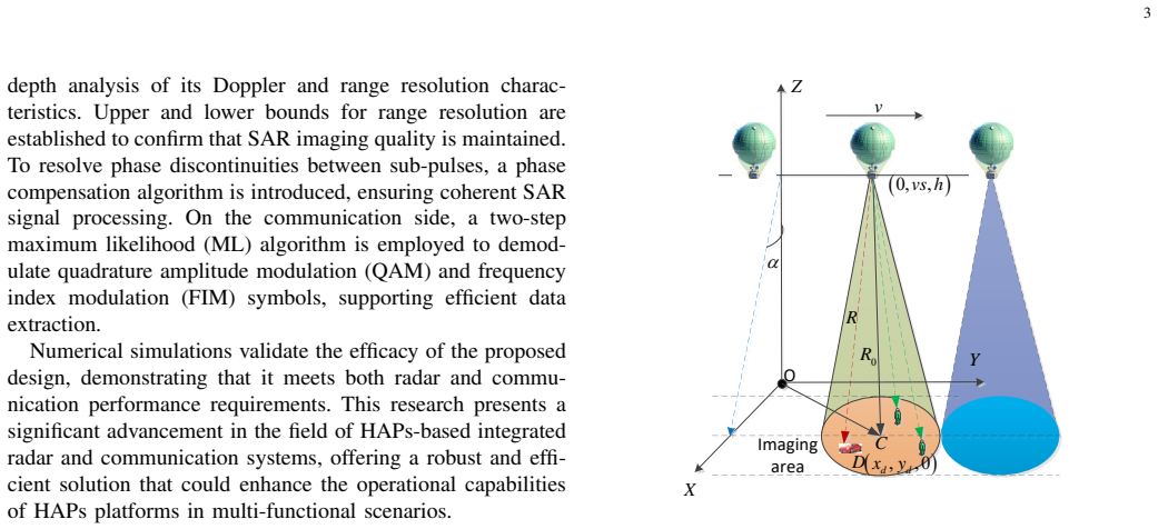
- [Appendix A / Section II-A (Eqs. (8), (39)-(41))] The ambiguity function derivation in Appendix A decomposes χ into a principal term (m=m') and a coupling term (m≠m') and discards the coupling term with only the assertion that it 'usually serves as interference and has a lesser impact on resolution' (Eq. (41)). No bound on the magnitude of the coupling term is provided, and for the random FIM patterns required by communication, the dropped terms contribute at difference frequencies (a_m-a_m')B_s and can lie within the main-lobe region of the principal term. The exact SAR-processed response in Eq. (26) is derived without this approximation, but Section III-C analyzes only the two extremal patterns (a_m constant and a_m=m); the paper does not prove that the main-lobe width of the combined sinc-sum term in Eq. (26) lies between c/(2B_w) and c/(2B_s) for arbitrary a_m. Since the range-resolution bound of Eq. (16) is a central claim, this gap must be closed, for example by a worst-case or statistical bound on the coupling term or by a direct analysis of Eq. (26).
- [Section II-A, Eq. (16)] The inequality in Eq. (16) is printed in the reverse order. Because B_s = B_w/M, the quantity c/(2B_s) is M times larger than c/(2B_w); the correct bound is c/(2B_w) ≤ ρ_r ≤ c/(2B_s). This is consistent with the surrounding text, which calls c/(2B_s) the upper bound and c/(2B_w) the minimum bound, and with the simulation result in Table I (about 4.2 m for M=4, lying between 1.875 m and 7.5 m), but the equation as printed states the opposite and should be corrected.
- [Section III-B, Eq. (29)] The de-chirp model in Eq. (29) is incomplete. For a received sub-pulse whose delay τ(s) differs from the reference delay τ_ref, the product of Eq. (27) with the conjugate of Eq. (28) contains a residual beat term proportional to K(τ(s)-τ_ref)(t-Δ_{kM+m}) and a delay-dependent quadratic phase; these terms cannot be 'absorbed into h_{kM+m}' because h is a constant Rayleigh coefficient and the beat term varies over the sub-pulse duration. Unless τ(s)≈τ_ref is justified, the FIM and QAM detectors in Eqs. (32)-(33) and the BER results in Figs. 14-15 are based on an idealized model that omits a physically present term. The paper should either include this term and show that it is negligible in the scenario of Fig. 1, or modify the communication receiver to compensate for the delay mismatch.
minor comments (6)
- [Eq. (3)] The quadratic-phase term in Eq. (3) is missing the chirp rate K: the exponent should read 1/2 K(t-Δt_m)(t-Δt_m) as in Eq. (2).
- [Section II-A, after Eq. (15)] The sentence after Eq. (15) says the range resolution is consistent with an LFM waveform of pulse width T_s and bandwidth B_s, but the derived value c/(2B_w) corresponds to the full-band LFM (T_w, B_w); please correct this wording.
- [Section IV-A] The paragraph beginning 'To further evaluate the advantages and disadvantages...' appears twice verbatim in Section IV-A; one copy should be removed.
- [Notation (Eq. (8), Eq. (40), Fig. 3)] The FIM index range is inconsistent: Eq. (8) and the text use m=1,...,M, while Appendix A and Eq. (40) use m=0,...,M-1, and Fig. 3 uses a_1,...,a_8; please harmonize the indexing.
- [Section IV-A, Fig. 7] The specific random FIM pattern a_m used in the SAR simulation is not stated; please provide it or report imaging metrics averaged over several random patterns so the reader can assess how representative Fig. 7 is.
- [Section III-A, before Eq. (21)] The claim that the phase of the third term in Eq. (20) is 'much less' than the first two terms is not quantified; for the simulation parameters π K T_s^2 ≈ 628 rad, which is not obviously small. Please justify or rephrase.
Circularity Check
No significant circularity: the FIM-LFM resolution claims are derived from the ambiguity function and independently confirmed by simulation.
full rationale
The paper's central claims—the ambiguity function of Eq. (8), the Doppler resolution of Eq. (10), and the range-resolution bounds of Eq. (16)—are obtained by direct algebraic manipulation of the transmitted signal model in Eqs. (2)-(3) and standard sinc/Fourier identities, not by fitting parameters to the simulation outputs. The two bounding cases (a_m constant and a_m = m) are evaluated in closed form, while the SAR simulations use a random FIM pattern and yield a measured range resolution near 4.2 m, which lies between the stated 1.875 m and 7.5 m limits; the bounds are therefore not manufactured from the simulated data. The only apparent self-citation (reference [1], which includes co-author Alouini) is contextual background on HAP networks and is not load-bearing for any derivation. The approximation in Appendix A that drops the cross-coupling term (Eq. (41)) is an unquantified analytical shortcut, and Eq. (16) appears to have a typographical reversal of the two bounds, but neither issue constitutes circularity: the dropped term is not defined in terms of the claimed resolution, and no fitted quantity is renamed as a prediction. The analysis is self-contained against the stated signal model and standard radar ambiguity-function theory.
Assumptions & free parameters
assumptions (5)
- ad hoc to paper Cross-coupling terms between sub-pulses in the ambiguity function are negligible for resolution analysis
- domain assumption QAM symbols are known to the SAR receiver
- domain assumption Communication link is LOS Rayleigh fading with perfect channel knowledge and frame synchronization
- ad hoc to paper Delay-dependent de-chirp terms collapse into the complex channel coefficient h
- standard math Second-order Taylor expansion of the slant range R(s)
Cite this review
Pith. "Pith review of Design of Frequency Index Modulated Waveforms for Integrated SAR and Communication on High-Altitude Platforms (HAPs)." pith.science (2026). https://pith.science/paper/HZJFVQYY
@misc{pith2026241217035,
  author       = {Pith},
  title        = {Pith review of: Design of Frequency Index Modulated Waveforms for Integrated SAR and Communication on High-Altitude Platforms (HAPs)},
  year         = {2026},
  howpublished = {\url{https://pith.science/paper/HZJFVQYY}},
  note         = {Machine review of arXiv:2412.17035}
}
read the original abstract
This paper, addressing the integration requirements of radar imaging and communication for High-Altitude Platform Stations (HAPs) platforms, designs a waveform based on linear frequency modulated (LFM) frequency-hopping signals that combines synthetic aperture radar (SAR) and communication functionalities. Specifically, each pulse of an LFM signal is segmented into multiple parts, forming a sequence of sub-pulses. Each sub-pulse can adopt a different carrier frequency, leading to frequency hops between sub-pulses. This design is termed frequency index modulation (FIM), enabling the embedding of communication information into different carrier frequencies for transmission. To further enhance the data transmission rate at the communication end, this paper incorporates quadrature amplitude modulation (QAM) into waveform design. %For the SAR portion, this approach reduces the ADC sampling requirements while maintaining range resolution. The paper derives the ambiguity function of the proposed waveform and analyzes its Doppler and range resolution, establishing upper and lower bounds for the range resolution. In processing SAR signals, the receiver first removes QAM symbols, and to address phase discontinuities between sub-pulses, a phase compensation algorithm is proposed to achieve coherent processing. For the communication receiver, the user first performs de-chirp processing and then demodulates QAM symbols and FIM index symbols using a two-step maximum likelihood (ML) algorithm. Numerical simulations further confirm the theoretical validity of the proposed approach.
Figures


Figures from the paper (12 more)


Reference graph
Works this paper leans on
-
[1]
Cellular Network From the Sky: Toward People-Centered Smart Communities,
B. E. Y . Belmekki, A. J. Aljohani, S. A. Althubaity, A. A. Harthi, K. Bean, A. Aijaz, and M.-S. Alouini, “Cellular Network From the Sky: Toward People-Centered Smart Communities,” IEEE Open Journal of the Communications Society , vol. 5, pp. 1916–1936
work page 1916
-
[2]
G. Kurt, M. G. Khoshkholgh, S. Alfattani, A. Ibrahim, T. S. J. Darwish, M. S. Alam, H. Yanikomeroglu, and A. Yongacoglu. A Vision and Framework for the High Altitude Platform Station (HAPS) Networks of the Future. [Online]. Available: http://arxiv.org/abs/2007.15088
work page Pith review arXiv 2007
-
[3]
High altitude platform stations: the new network energy efficiency enabler in the 6G era,
T. Song, D. Lopez, M. Meo, N. Piovesan, and D. Renga, “High altitude platform stations: the new network energy efficiency enabler in the 6G era,” in 2024 IEEE Wireless Communications and Networking Conference (WCNC), 2024, pp. 1–6
work page 2024
-
[4]
High-altitude plat- forms—present situation and technology trends,
F. A. d’Oliveira, F. C. L. d. Melo, and T. C. Devezas, “High-altitude plat- forms—present situation and technology trends,” Journal of Aerospace Technology and Management, vol. 8, no. 3, pp. 249–262, 2016
2016
-
[5]
J. Li, J. Paden, C. Leuschen, F. Rodriguez-Morales, R. D. Hale, E. J. Arnold, R. Crowe, D. Gomez-Garcia, and P. Gogineni, “High-altitude radar measurements of ice thickness over the antarctic and greenland ice sheets as a part of operation icebridge,” IEEE Transactions on Geoscience and Remote Sensing , vol. 51, no. 2, pp. 742–754, 2012
work page 2012
-
[6]
Can high altitude platform stations make 6G sustainable?
D. Renga and M. Meo, “Can high altitude platform stations make 6G sustainable?” IEEE Communications Magazine , vol. 60, no. 9, pp. 75– 80, 2022
work page 2022
-
[7]
High altitude platform multichannel SAR for wide-area and staring imaging,
W.-Q. Wang and H. Shao, “High altitude platform multichannel SAR for wide-area and staring imaging,” IEEE Aerospace and Electronic Systems Magazine, vol. 29, no. 5, pp. 12–17, 2014
work page 2014
-
[8]
Joint resource allocations for energy consumption optimization in HAPS- aided MEC-NOMA systems,
X. Yu, X. Zhang, Y . Rui, K. Wang, X. Dang, and M. Guizani, “Joint resource allocations for energy consumption optimization in HAPS- aided MEC-NOMA systems,” IEEE Journal on Selected Areas in Communications, pp. 1–1, 2024
work page 2024
Show all 51 references
-
[9]
Multi-HAPS thz satellite communication: Error and capacity analyses under I/Q imbalance,
E. S. Ahrazoglu, I. Altunbas, and E. Erdogan, “Multi-HAPS thz satellite communication: Error and capacity analyses under I/Q imbalance,”IEEE Sensors Journal, pp. 1–1, 2024
2024
-
[10]
Design of energy efficient Multi-HAPS assisted hybrid rf/fso satellite communi- cation systems with optimal placement,
S. E. Turk, E. S. Ahrazoglu, E. Erdogan, and I. Altunbas, “Design of energy efficient Multi-HAPS assisted hybrid rf/fso satellite communi- cation systems with optimal placement,” IEEE Transactions on Green Communications and Networking , pp. 1–1, 2024
2024
-
[11]
A tutorial on joint radar and communication transmission for vehicular networks—part i: Background and fundamen- tals,
F. Liu and C. Masouros, “A tutorial on joint radar and communication transmission for vehicular networks—part i: Background and fundamen- tals,” IEEE Communications Letters , vol. 25, no. 2, pp. 322–326, 2021
2021
-
[12]
Joint radar- communication strategies for autonomous vehicles: Combining two key automotive technologies,
D. Ma, N. Shlezinger, T. Huang, Y . Liu, and Y . C. Eldar, “Joint radar- communication strategies for autonomous vehicles: Combining two key automotive technologies,” IEEE signal processing magazine , vol. 37, no. 4, pp. 85–97, 2020
2020
-
[13]
Multicarrier radar-communications wave- form design for rf convergence and coexistence,
M. Bic ˘a and V . Koivunen, “Multicarrier radar-communications wave- form design for rf convergence and coexistence,” in ICASSP 2019- 2019 IEEE International Conference on Acoustics, Speech and Signal Processing (ICASSP). IEEE, 2019, pp. 7780–7784
2019
-
[14]
Aoi-aware waveform design for cooperative joint radar-communications systems with online prediction of radar target property,
Z. Li, F. Hu, Q. Li, Z. Ling, Z. Chang, and T. H ¨am¨al¨ainen, “Aoi-aware waveform design for cooperative joint radar-communications systems with online prediction of radar target property,” IEEE Transactions on Communications, vol. 72, no. 10, pp. 6029–6043, 2024
2024
-
[15]
An overview of signal processing techniques for joint communication and radar sensing,
J. A. Zhang, F. Liu, C. Masouros, R. W. Heath, Z. Feng, L. Zheng, and A. Petropulu, “An overview of signal processing techniques for joint communication and radar sensing,” IEEE Journal of Selected Topics in Signal Processing, vol. 15, no. 6, pp. 1295–1315, 2021
2021
-
[16]
A survey on waveform design for radar-communication convergence,
A. Chakravarthi Mahipathi, B. Pardhasaradhi, P. Lingadevaru, P. Srihari, J. D’Souza, and L. Reddy Cenkeramaddi, “A survey on waveform design for radar-communication convergence,” IEEE Access , vol. 12, pp. 75 442–75 461, 2024
2024
-
[17]
Integrated sensing and communication - the ISAC technology,
H. Ma, “Integrated sensing and communication - the ISAC technology,” in 2024 IEEE 2nd International Conference on Sensors, Electronics and Computer Engineering (ICSECE) , 2024, pp. 225–229
2024
-
[18]
Adaptive OFDM inte- grated radar and communications waveform design based on information theory,
Y . Liu, G. Liao, J. Xu, Z. Yang, and Y . Zhang, “Adaptive OFDM inte- grated radar and communications waveform design based on information theory,” IEEE Communications Letters , vol. 21, no. 10, pp. 2174–2177, 2017
2017
-
[19]
Waveform design and performance analysis for full-duplex integrated sensing and communication,
Z. Xiao and Y . Zeng, “Waveform design and performance analysis for full-duplex integrated sensing and communication,” IEEE Journal on Selected Areas in Communications, vol. 40, no. 6, pp. 1823–1837, 2022
2022
-
[20]
Performance analysis of joint radar and communication using ofdm and otfs,
L. Gaudio, M. Kobayashi, B. Bissinger, and G. Caire, “Performance analysis of joint radar and communication using ofdm and otfs,” in 2019 IEEE International Conference on Communications Workshops (ICC Workshops). IEEE, 2019, pp. 1–6. 13
2019
-
[21]
A novel joint angle-range-velocity estimation method for MIMO-OFDM ISAC systems,
Z. Xiao, R. Liu, M. Li, Q. Liu, and A. L. Swindlehurst, “A novel joint angle-range-velocity estimation method for MIMO-OFDM ISAC systems,” IEEE Transactions on Signal Processing , 2024
2024
-
[22]
An ofdm system concept for joint radar and communications operations,
C. Sturm, T. Zwick, and W. Wiesbeck, “An ofdm system concept for joint radar and communications operations,” in VTC Spring 2009-IEEE 69th Vehicular Technology Conference. IEEE, 2009, pp. 1–5
2009
-
[23]
Analysis and design for pilot power allocation and placement in OFDM based integrated radar and communication in automobile systems,
H.-W. Hsu, M.-C. Lee, M.-X. Gu, Y .-C. Lin, and T.-S. Lee, “Analysis and design for pilot power allocation and placement in OFDM based integrated radar and communication in automobile systems,” IEEE Transactions on Vehicular Technology , vol. 71, no. 2, pp. 1519–1535, 2021
2021
-
[24]
Low pmepr ofdm radar waveform design using the iterative least squares algorithm,
T. Huang and T. Zhao, “Low pmepr ofdm radar waveform design using the iterative least squares algorithm,” IEEE Signal Processing Letters , vol. 22, no. 11, pp. 1975–1979, 2015
1975
-
[25]
Low-complexity waveform design for papr reduction in integrated sensing and communication systems based on ADMM,
J. Wu, L. Li, W. Lin, J. Liang, and Z. Han, “Low-complexity waveform design for papr reduction in integrated sensing and communication systems based on ADMM,” IEEE Sensors Journal , 2024
2024
-
[26]
OFDM achieves the lowest ranging sidelobe under random ISAC signaling,
F. Liu, Y . Zhang, Y . Xiong, S. Li, W. Yuan, F. Gao, S. Jin, and G. Caire, “OFDM achieves the lowest ranging sidelobe under random ISAC signaling,” arXiv preprint arXiv:2407.06691 , 2024
2024 arXiv
-
[27]
Waveform design for mimo-ofdm integrated sensing and communication system: An information theoretical approach,
Z. Wei, J. Piao, X. Yuan, H. Wu, J. A. Zhang, Z. Feng, L. Wang, and P. Zhang, “Waveform design for mimo-ofdm integrated sensing and communication system: An information theoretical approach,” IEEE Transactions on Communications , 2023
2023
-
[28]
MIMO-OFDM ISAC waveform design for range-doppler sidelobe suppression,
P. Li, M. Li, R. Liu, Q. Liu, and A. L. Swindlehurst, “MIMO-OFDM ISAC waveform design for range-doppler sidelobe suppression,” arXiv preprint arXiv:2406.17218, 2024
2024 arXiv
-
[29]
Enhancing frequency hopping security in isac systems: A physical layer security approach,
A. K. Boroujeni, G. Bagheri, and S. K ¨opsell, “Enhancing frequency hopping security in isac systems: A physical layer security approach,” in 2024 IEEE 4th International Symposium on Joint Communications & Sensing (JC&S). IEEE, 2024, pp. 1–6
2024
-
[30]
Frequency-hopping MIMO radar-based communications: An overview,
K. Wu, J. A. Zhang, X. Huang, and Y . J. Guo, “Frequency-hopping MIMO radar-based communications: An overview,” IEEE Aerospace and Electronic Systems Magazine , vol. 37, no. 4, pp. 42–54, 2021
2021
-
[31]
Co-design of joint radar and communications systems utilizing frequency hopping code diversity,
X. Wang and J. Xu, “Co-design of joint radar and communications systems utilizing frequency hopping code diversity,” in2019 IEEE Radar Conference (RadarConf). IEEE, 2019, pp. 1–6
2019
-
[32]
A dual-function MIMO radar-communications system using frequency-hopping waveforms,
A. Hassanien, B. Himed, and B. D. Rigling, “A dual-function MIMO radar-communications system using frequency-hopping waveforms,” in 2017 IEEE Radar Conference (RadarConf) . IEEE, 2017, pp. 1721– 1725
2017
-
[33]
Orthogonal time frequency space modulation—part iii: ISAC and potential applications,
W. Yuan, Z. Wei, S. Li, R. Schober, and G. Caire, “Orthogonal time frequency space modulation—part iii: ISAC and potential applications,” IEEE Communications Letters , vol. 27, no. 1, pp. 14–18, 2022
2022
-
[34]
Joint transceiver beamforming and reflecting design for active RIS-aided ISAC systems,
Q. Zhu, M. Li, R. Liu, and Q. Liu, “Joint transceiver beamforming and reflecting design for active RIS-aided ISAC systems,”IEEE Transactions on Vehicular Technology, vol. 72, no. 7, pp. 9636–9640, 2023
2023
-
[35]
FRaC: FMCW-based joint radar-communications system via index modula- tion,
D. Ma, N. Shlezinger, T. Huang, Y . Liu, and Y . C. Eldar, “FRaC: FMCW-based joint radar-communications system via index modula- tion,” IEEE journal of selected topics in signal processing, vol. 15, no. 6, pp. 1348–1364, 2021
2021
-
[36]
MAJoRCom: A dual-function radar communication system using index modulation,
T. Huang, N. Shlezinger, X. Xu, Y . Liu, and Y . C. Eldar, “MAJoRCom: A dual-function radar communication system using index modulation,” IEEE Transactions on signal processing , vol. 68, pp. 3423–3438, 2020
2020
-
[37]
FMCW radar with broad- band communication capability,
P. Barrenechea, F. Elferink, and J. Janssen, “FMCW radar with broad- band communication capability,” in 2007 European Radar Conference . IEEE, 2007, pp. 130–133
2007
-
[38]
Design and analysis of frequency hopping-aided FMCW-based integrated radar and communi- cation systems,
M.-X. Gu, M.-C. Lee, Y .-S. Liu, and T.-S. Lee, “Design and analysis of frequency hopping-aided FMCW-based integrated radar and communi- cation systems,” IEEE Transactions on Communications, vol. 70, no. 12, pp. 8416–8432, 2022
2022
-
[39]
Waveform design for LFM-MPSK-based integrated radar and communication toward IoT applications,
R. Xie, K. Luo, and T. Jiang, “Waveform design for LFM-MPSK-based integrated radar and communication toward IoT applications,” IEEE Internet of Things Journal , vol. 9, no. 7, pp. 5128–5141, 2021
2021
-
[40]
Spatial modulation for joint radar-communications systems: De- sign, analysis, and hardware prototype,
D. Ma, N. Shlezinger, T. Huang, Y . Shavit, M. Namer, Y . Liu, and Y . C. Eldar, “Spatial modulation for joint radar-communications systems: De- sign, analysis, and hardware prototype,” IEEE Transactions on Vehicular Technology, vol. 70, no. 3, pp. 2283–2298, 2021
2021
-
[41]
Integrated sensing and communication for UA V-Borne SAR systems,
Z. Liu, F. Zesong, P. Liu, X. Wang, Z. Zheng, D. Zhou, and W. Yuan, “Integrated sensing and communication for UA V-Borne SAR systems,” in 2023 22nd International Symposium on Communications and Infor- mation Technologies (ISCIT). IEEE, 2023, pp. 1–6
2023
-
[42]
Evaluation of UA V-Based ISAC SAR imaging: Methods and performances,
M. Manzoni, S. Moro, F. Linsalata, M. G. Polisano, A. V . Monti- Guarnieri, and S. Tebaldini, “Evaluation of UA V-Based ISAC SAR imaging: Methods and performances,” in 2024 IEEE Radar Conference (RadarConf24). IEEE, 2024, pp. 1–6
2024
-
[43]
Trajectory and resource optimization for UA V synthetic aperture radar,
M.-A. Lahmeri, W. Ghanem, C. Knill, and R. Schober, “Trajectory and resource optimization for UA V synthetic aperture radar,” in 2022 IEEE Globecom Workshops (GC Wkshps) . IEEE, 2022, pp. 897–903
2022
-
[44]
UA V formation and resource allocation optimiza- tion for communication-assisted 3D InSAR sensing,
M.-A. Lahmeri, V . Mustieles-P ´erez, M. V ossiek, G. Krieger, and R. Schober, “UA V formation and resource allocation optimiza- tion for communication-assisted 3D InSAR sensing,” arXiv preprint arXiv:2407.06607, 2024
2024 arXiv
-
[45]
OFDM synthetic aperture radar imaging with sufficient cyclic prefix,
T. Zhang and X.-G. Xia, “OFDM synthetic aperture radar imaging with sufficient cyclic prefix,” IEEE Transactions on Geoscience and Remote Sensing, vol. 53, no. 1, pp. 394–404, 2014
2014
-
[46]
First demonstration of joint wireless communication and high-resolution SAR imaging using airborne MIMO radar system,
J. Wang, X.-D. Liang, L.-Y . Chen, L.-N. Wang, and K. Li, “First demonstration of joint wireless communication and high-resolution SAR imaging using airborne MIMO radar system,” IEEE Transactions on Geoscience and Remote Sensing , vol. 57, no. 9, pp. 6619–6632, 2019
2019
-
[47]
Radar sensor and data communication system based on OFDM without cyclic prefix,
G. Liu, Y . Wang, and W. Yang, “Radar sensor and data communication system based on OFDM without cyclic prefix,” IEEE Sensors Journal , vol. 23, no. 7, pp. 7578–7590, 2022
2022
-
[48]
Waveform design for watermark framework based DFRC system with application on joint SAR imaging and communication,
J. Yang, Y . Tan, X. Yu, G. Cui, and D. Zhang, “Waveform design for watermark framework based DFRC system with application on joint SAR imaging and communication,” IEEE Transactions on Geoscience and Remote Sensing , vol. 61, pp. 1–14, 2023
2023
-
[49]
The DLR high altitude platform synthetic aperture radar instrument HAPSAR,
M. Jirousek, M. Peichl, S. Anger, S. Dill, and M. Limbach, “The DLR high altitude platform synthetic aperture radar instrument HAPSAR,” in EUSAR 2024; 15th European Conference on Synthetic Aperture Radar , 2024, pp. 1244–1248
2024
-
[50]
Synthetic aperture radar design for a high-altitude platform,
M. Jirousek, M. Peichl, S. Anger, M. Engel, S. Dill, R. Scheiber, and S. Baumgartner, “Synthetic aperture radar design for a high-altitude platform,” in EUSAR 2022; 14th European Conference on Synthetic Aperture Radar, 2022, pp. 1–4
2022
-
[51]
Design of a synthetic aperture radar instrument for a high-altitude platform,
M. Jirousek, M. Peichl, S. Anger, S. Dill, and M. Engel, “Design of a synthetic aperture radar instrument for a high-altitude platform,” in IGARSS 2023 - 2023 IEEE International Geoscience and Remote Sensing Symposium, 2023, pp. 2045–2048
2023
Reviewed August 11, 2026 · model on record in the stance chip above.
Discussion (0). Continue with ORCID to comment.