REVIEW 3 major objections 5 minor 27 references
Active Damping of Power Oscillations Following Frequency Changes in Low Inertia Power Systems
T0 review · 3 major / 5 minor · reviewed 2026-08-14 · deepseek-v4-flash
Pith's one-line read This paper derives exact closed-form expressions for the PSS1A stabilizer and AVR output signals during linear and nonlinear frequency transients, and states that these expressions describe active damping of power oscillations in…
desk verdict A competent open-loop transfer-function calculation whose title and conclusion claim active damping that the paper never derives, because the PSS/AVR output is never fed back into the generator dynamics. read the letter →
The pith
A machine-rendered reading of the paper's core claim, the machinery that carries it, and where it could break.
The reading
What carries the argument
The load-bearing object is the cascaded PSS1A-AVR transfer-function chain: the IEEE PSS1A power system stabilizer, consisting of a washout filter, two lead-lag compensators, and a gain block, feeding the automatic voltage regulator, with the generator's rotor-angle equation $\ddot{\delta}+\beta\dot{\delta}+\xi\sin\delta=\tau_r$ supplying the input signal. Each block in the chain is a first-order linear filter, so when the input is a damped oscillation or a sum of eigenfunctions, every intermediate signal and the final output $V_{\mathrm{out}}$ can be written in closed form by repeated application of the s-plane and first-order-equation solution. This machinery converts the nonlinear dynamics of the two-body grid model into explicit formulas for the stabilizer output, which is what the paper identifies as the active-damping signal.
What would settle it
Run a closed-loop transient simulation of the same two-body generator model with the analytic $V_{\mathrm{out}}$ injected into the excitation loop, and compare the rotor-angle swing $\delta(t)$ against the case without the stabilizer; if adding $V_{\mathrm{out}}$ does not reduce the oscillation amplitude or settling time, the active-damping claim fails.
Extended reading notes
Core claim
The paper's central claim is that an exact analytic solution describes the effect of the PSS1A and AVR in stabilizing a generator after a transient fault. The solution is built by feeding the rotor-angle, bus-frequency, or electrical-power signal from the two-body low-inertia model into the cascaded transfer-function blocks of the IEEE PSS1A and AVR, and solving the resulting linear system in the s-plane. For a small disturbance, the input is a damped sinusoid and the PSS/AVR outputs are explicit sums of decaying sinusoids and exponential terms; for a large disturbance, the input is written as a sum of eigenfunctions of the system matrix, and the same output forms follow. The authors conclude that the method is not confined by fault magnitude, inertia values, or system parameters, and that it allows the role of stabilizers on high-renewable grids to be explored without simulation.
Load-bearing premise
The damping conclusion presumes that the computed PSS/AVR output voltage $V_{\mathrm{out}}$ actually changes the electromagnetic torque and damps rotor-angle oscillations, but the paper's equations of motion contain no term coupling that output voltage to the torque, so the stabilizing effect is assumed rather than demonstrated.
Editorial extensions
If this is right
- Because the outputs are closed form, a single transient's PSS/AVR response can be computed for any fault amplitude and any inertia ratio without running a time-domain simulation.
- The analytic framework covers both the cage and Kuramoto-like descriptions of the grid, so the conclusions are not tied to one modelling choice.
- For inputs built from successive abrupt events, the sine-envelope input still yields closed-form outputs, so the method reaches realistic rate-of-change-of-frequency sequences.
- The resulting formulas give a direct basis for tuning PSS1A gains and time constants and for comparing alternative stabilizer types on the same analytic footing.
Reading between the lines
- A natural completion of the argument would be to insert the computed output voltage $V_{\mathrm{out}}$ into the rotor-angle equation as an additional torque term; the equations as written leave that feedback path implicit.
- The same eigenfunction expansion could be applied to a multi-machine grid by enlarging the system matrix, turning each stabilizer's closed-form output into a per-unit torque contribution that yields analytic damping ratios per mode.
- The formulas suggest a testable design rule: for each grid-to-generator inertia ratio $x=J_{\mathrm{grid}}/J_{\mathrm{gen}}$, the stabilizer transfer function could be optimized against the rotor-angle eigenvalues, potentially identifying an inertia threshold below which PSS1A cannot stabilize the swing.
- A direct quantitative comparison of the analytic $V_{\mathrm{out}}$ with the simulated PSS/AVR response would isolate how much of the discrepancy comes from the transfer-function reduction versus the underlying two-body model.
Signed reviews
Editorial analysis
A structured set of objections, weighed in public.
Referee Report
Summary. The paper develops closed-form analytic expressions for the outputs of an IEEE PSS1A power system stabilizer cascade with an automatic voltage regulator (AVR) when driven by transient input signals representative of low-inertia grid disturbances. The input signals are modeled as a damped sinusoid for linear transients and as a sum of eigenfunctions for nonlinear transients, following the authors' earlier two-body torsional-pendulum model. The authors present time- and frequency-domain plots of the input, PSS output, and AVR output, and claim in the conclusion to have created an exact analytic solution describing the stabilizing effect of the PSS1A and AVR on a generator's response to a transient fault.
Significance. If the central damping claim were supported, the paper would offer a valuable analytic complement to simulation-based PSS design in low-inertia systems, and the eigenfunction-expansion treatment of the nonlinear input is an interesting direction. The transfer-function cascade derivations in Appendix B appear internally consistent, and the paper correctly uses the standard IEEE PSS1A/AVR block structure. However, the paper's actual contribution as presented is an open-loop controller-response calculation; it never demonstrates the claimed active damping of power oscillations, so the significance in its current form is limited.
major comments (3)
- [Section VI and Appendix A, Eq. (A4)] The rotor-angle equation of motion (A4) contains no term that depends on Vout or on the excitation voltage; Eqs. (A1)-(A3) couple only mechanical angles, angular velocities, damping torques, and applied torques. The signals VPSS(t) and Vout(t) computed in Eqs. (7)-(8) and (11)-(12) are therefore open-loop outputs of the PSS1A/AVR cascade for a prescribed input, and the paper never shows that Vout changes the electromagnetic torque so as to damp the rotor-angle oscillation or the electrical power oscillation. Consequently, the conclusion's claim of "an exact analytic solution describing the effect of the PSS1A and AVR in stabilizing the response" is unsupported by the derivation, and Figs. 4-7 illustrate controller signals rather than stabilized power oscillations. To support the central claim, the authors must either close the loop by inserting a Vout-dependent torque term into (A4) and solving or simulating the coupled system, or provide a closed-loop time-domain simulation in which δ(t) and Pel(t) are shown to be damped.
- [Section V and Appendix C] The nonlinear input representation (9) uses eigenfunctions from reference [12], which is listed as "submitted" and therefore unavailable to the reader, and Appendix C omits the coefficients for the nonlinear responses with the statement that they are "easily reproduced." This makes the claimed exactness of the nonlinear solution unverifiable from the manuscript alone. Please provide the coefficient definitions and the derivation, or make reference [12] accessible, before the exactness claim can be assessed.
- [Section II and simulation claims] The introduction states that "the behavior simulated with a computer model from MatLab-SimPowerSystems is reviewed," but the manuscript contains no transient simulation results; the only Simulink-based results shown are Bode plots in Fig. 3. A comparison of the analytic Vout(t) with a time-domain simulation of the PSS1A/AVR cascade would validate the open-loop transfer-function calculation, and a closed-loop simulation is essential to support the damping claim.
minor comments (5)
- [Section IV, last paragraph] The sentence "We consider the more relevant case of large rotor angle deviation (nonlinear transient response) in Section 4" should refer to Section V, not Section 4.
- [Equations throughout] Many displayed equations suffer from poor typesetting, with subscripts, superscripts, and fractions running together (e.g., Eq. (1) and the coefficient lists in Appendix B); a careful formatting pass is needed for readability.
- [Eq. (1) and Nomenclature] The constant V∞ appearing in Eq. (1) is not explicitly defined; please state that it is the steady-state value of Vin(t) as t → ∞.
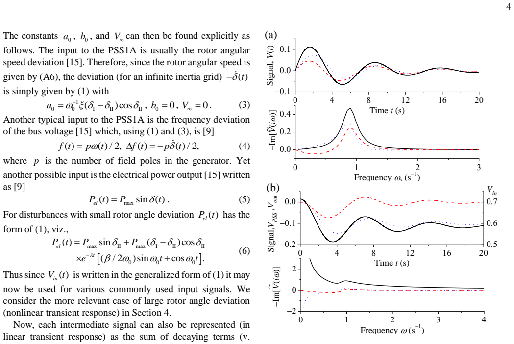
- [Fig. 6] The vertical axis of the time-domain panels in Fig. 6 is unlabeled; please add units (e.g., volts or per-unit) for V(t) so that the reader can interpret the signal magnitudes.
- [References] Reference [12] is cited as "submitted"; if this companion paper has since been published, the citation should be updated to its final venue and year.
Circularity Check
Nonlinear input and eigen-coefficients are imported from the authors' own submitted reference [12], making the exact-solution claim load-bearing on self-citation; no fitted prediction reduces by construction, and the damping assertion is an open-loop gap rather than circularity.
-
self citation load bearing
[Section V (Eqs. (9)-(10)) and Conclusion; cf. reference [12]]
"In conclusion, we have created an exact analytic solution describing the effect of the PSS1A and AVR in stabilizing the response of a generator to a transient fault based on our recently developed dynamical model of low inertia grids [10],[12]. ... Here λ_j represent the eigenvalues of our dynamical system whereas the amplitudes a_{0j} are determined from the corresponding eigenfunctions and the initial conditions [12]. ... An exact representation of the input signal for arbitrary system parameters and disturbance amplitude can be determined as in Ref."
The nonlinear input signal (9) is the only route by which generator dynamics enter the PSS1A/AVR transfer-function calculation, and its eigenpairs (λ_j, a_{0j}) are not derived in this paper; they are taken from the authors' own reference [12], which the reference list itself marks as 'submitted'. The subsequent 'exact' nonlinear output formulas (11)-(12) and the concluding exact-solution claim therefore inherit their generator-specific content from that self-citation rather than from any derivation or independent verification presented here. The PSS/AVR transfer-function part is standard IEEE material, but the load-bearing nonlinear dynamical input reduces to a prior author-supplied result.
full rationale
The paper does not fit a parameter and then rename it a prediction, nor does it smuggle in a uniqueness theorem or rename a known empirical pattern: the PSS1A and AVR transfer functions are taken from the IEEE standard [15], and the linear transient input (Eq. 1) is solved explicitly from the rotor-angle equation with λ and ω0 given in Eq. 2. The central circularity-relevant weakness is that the nonlinear input representation (Eq. 9) and its amplitudes/eigenvalues are imported from the authors' own unpublished-at-submission reference [12], and Appendix C declines to give the nonlinear coefficient calculations as 'easily reproduced', so the exact nonlinear solution cannot be checked from the paper and is load-bearing on self-citation. A separate, important gap is that V_out is never inserted into the equations of motion (A1)-(A4), so the claimed active damping of rotor-angle oscillations is asserted rather than derived; however, that is a correctness/open-loop issue, not a circular reduction, and it does not by itself raise the circularity score. Overall, there is one significant load-bearing self-citation, while the standard transfer-function calculation retains independent content, giving a score of 4.
Assumptions & free parameters
assumptions (5)
- domain assumption The IEEE PSS1A and AVR block diagrams in Fig. 2 accurately represent the physical stabilizer and voltage regulator.
- domain assumption The two-mass cage and Kuramoto models from [10] and [12] describe a grid-connected generator in a low-inertia system.
- ad hoc to paper The input signal to the PSS can be represented exactly as a damped sinusoid (1) for linear transients and as an eigenfunction expansion (9) for nonlinear transients.
- standard math Cascaded linear transfer functions obey superposition, so the PSS and AVR outputs are sums of exponentials and oscillatory terms.
- ad hoc to paper A sequence of rapid events can be modeled as a sine-wave envelope input (13) for a ROCOF event.
Cite this review
Pith. "Pith review of Active Damping of Power Oscillations Following Frequency Changes in Low Inertia Power Systems." pith.science (2026). https://pith.science/paper/I2MNKHK3
@misc{pith2026190804405,
  author       = {Pith},
  title        = {Pith review of: Active Damping of Power Oscillations Following Frequency Changes in Low Inertia Power Systems},
  year         = {2026},
  howpublished = {\url{https://pith.science/paper/I2MNKHK3}},
  note         = {Machine review of arXiv:1908.04405}
}
read the original abstract
The absolute requirement to increase the amount of energy generation from renewable sources e.g. predominantly asynchronously connected wind turbines and photovoltaic installations, may in practice during transient events (where frequency changes are examined) excite oscillatory response of the power output of large grid connected synchronous-generators. The response of such generators must be controlled either by varying the applied torque of a turbine or by altering the electromagnetic torque in the airgap. Choosing the latter, the adequacy of a voltage regulator, particularly that of the embedded Power System Stabilizer (PSS) circuit, is investigated using the IEEE PSS1A model for the automatic voltage regulator of a synchronous generator driven by a gas turbine. The response is obtained via closed form analytic solutions for both small (linear) and large (nonlinear) scale transient events in the energy grid system. In tandem with the analytical study, the behavior simulated with a computer model from MatLab-SimPowerSystems is reviewed.
Figures


Reference graph
Works this paper leans on
-
[12]
M. Zarifakis, W. T. Coffey, Yu. P. Kalmykov, S. V. Titov, D. J. Byrne, and W. J. Dowl ing, “Coupled nonlinear oscillator models for the transient stability of power generating stations connected to low inertia systems”, IEEE Trans. Power Syst., submitted
-
[1]
Impact of Low Rotational Inertia on Power System Stability and Operation
A. Ulbig, T. S. Borsche, and G. Andersson, “Impact of Low Rotational Inertia on Power System Stability and Operation” in Proc. IFAC World Congr., vol. 47, no. 3, pp. 7290–729, Aug. 2014
work page 2014
-
[2]
S. Eftekharnejad, V. Vittal, G. T. Heydt, B. Keel, and J. Loehr, “Small signal stability assessment of power systems with increased penetration of photovoltaic generation: A case study,” IEEE Trans. Sustain. Energy, vol. 4, no. 4, pp. 960–967, Oct. 2013
work page 2013
-
[3]
Identification and predictive analysis of a multi-area wecc power system model using synchrophasors
G. Chavan, M. Weiss, A. Chakrabortty, S. Bhattacharya, A. Salazar, and F. Habibi-Ashrafi, “Identification and predictive analysis of a multi-area wecc power system model using synchrophasors”, IEEE Trans. Smart Grid, vol. 8, no. 4, July 2017
work page 2017
-
[4]
Retrofit control of wind -integrated power systems,
T. Sadamoto, A. Chakrabortty, T. Ishizaki, and J. -I. Imura, “Retrofit control of wind -integrated power systems,” IEEE Trans. Power Syst. , vol. 33, no. 3, pp. 2804–2815, May 2018
work page 2018
-
[5]
Synchronizing torque impacts on rotor speed in power systems
M. Bakhtvar, E. Vittal, K. Zheng, and A. Keane, “Synchronizing torque impacts on rotor speed in power systems”, IEEE Trans. Power Syst., vol. 32, no. 3, pp. 1927-1935, May 2017
work page 1927
-
[6]
Grid Code Modification Proposal MPID229 ROCOF, www.eirgrid.com
-
[7]
Nonlinear Power System Analysis using Koopman Mode Decomposit ion and Perturbation Theory
M. A. Hernández-Ortega and A. R. Messina, “Nonlinear Power System Analysis using Koopman Mode Decomposit ion and Perturbation Theory”, IEEE Trans. Power Syst., vol. 33, no. 5, Sept. 2018
work page 2018
Show all 27 references
-
[8]
Global stability analysis using the eigenfunctions of the Koopman operator,
A. Mauroy and I. Mezić, “Global stability analysis using the eigenfunctions of the Koopman operator,” IEEE Trans. Autom. Control, vol. 61, no. 11, pp. 3356–3369, Nov. 2016
2016
-
[9]
Kundur, Power System Stability and Control
P. Kundur, Power System Stability and Control . New York, USA: McGraw Hill Inc., 1994
1994
-
[10]
Mathematical models for the t ransient stability of conventional power generating stations connected to low inertia systems
M. Zarifakis, W. T. Coffey, Yu. P. Kalmykov, and S. V. Titov, “Mathematical models for the t ransient stability of conventional power generating stations connected to low inertia systems”, Eur. Phys. J. Plus, vol. 132, no. 6, pp. 289-301, Jun. 2017
2017
-
[11]
Ruedenberg, Elektrische Schaltvorgänge, 5th Ed
R. Ruedenberg, Elektrische Schaltvorgänge, 5th Ed. Germany, Berlin: Springer-Verlag, 1974
1974
-
[13]
Risken, The Fokker –Planck Equation
H. Risken, The Fokker –Planck Equation . Germany, Berlin: Springer, 1984 (Second Edition, 1989)
1984
-
[14]
W. T. Coff ey and Y. P. Kalmykov, The Langevin Equation , 4th ed. Singapore: World Scientific, 2017
2017
-
[15]
1–207, Aug
IEEE recommended practice for excitation system models for power system stability studies , IEEE Standard 421.5 -2016 (Revision of IEEE Std 421.5-2005), pp. 1–207, Aug. 2016
2016
-
[16]
Padiyar, Power System Dynamics: Stability and Control , 2nd Ed
K.R. Padiyar, Power System Dynamics: Stability and Control , 2nd Ed. India, Hyderabad: BS Publications, 2008
2008
-
[17]
Kuramoto, Chemical Oscillations, Waves, and Turbulence
Y. Kuramoto, Chemical Oscillations, Waves, and Turbulence . Berlin, Germany: Springer, 1984
1984
-
[18]
Network susceptibilities: theory and applications
D. Manik, M. Rohden, H. Ronellenfitsch, X. Zhang , S. Hallerberg, D. Witthaut, and M. Timme, “Network susceptibilities: theory and applications”, Phys. Rev. E, vol. 95, no. 1, pp. 012319-012331, Jan. 2017
2017
-
[19]
Machowski, J
J. Machowski, J. Bialek, and J. Bumby, Power System Dynamics, Stability, and Control. New York, USA: John Wiley & Sons, 2008
2008
-
[20]
Analysis of a power grid using a Kuramoto -like model
G. Filatrella, A. H. Nielsen, and N. F. Pedersen, “Analysis of a power grid using a Kuramoto -like model”, Eur. Phys. J. B , vol. 61, no. 4, pp. 485-491, Feb. 2008
2008
-
[21]
M. W. Evans, G. J. Evans, W. T. Coffey, and P. Grigolini, Molecular Dynamics. New York, USA: Wiley, 1982
1982
-
[22]
W. T. Coffey, M. W. Evans, and P. Grigolini, Molecular Diffusion and Spectra. New York, USA: Wiley, 1984
1984
-
[23]
Inertial effects and d ielectric relaxation
E. P. Gross, “Inertial effects and d ielectric relaxation”, J. Chem. Phys., vol. 23, no. 8, pp. 1415-1423, Aug. 1955
1955
-
[24]
Relaxation processes and inertial effects I: free rotation about a fixed axis
R. A. Sack, “Relaxation processes and inertial effects I: free rotation about a fixed axis”, Proc. Phys. Soc. B, vol. 70, no. 4, pp. 402-413, Apr. 1957
1957
-
[25]
Complex susceptibility of the cage model of polar liquids
W. T. Coffey, G. P. Johari, Yu. P. Kalmykov, and S. V. Titov, “Complex susceptibility of the cage model of polar liquids”, J. Phys. Condens. Matter, vol. 15, no. 19, pp. 2961–2977, May 2003
2003
-
[26]
Itinerant oscill ator models of fluids
W. T. Coffey, Yu. P. Kalmykov, and S. V. Titov, “Itinerant oscill ator models of fluids”, in Advances in Chemical Physics , vol. 26, pp. 131 - 186, Jan. 2003
2003
-
[27]
Cage model of polar fluids: finite cage inertia generalization
W. T. Coffey, M. Zarifakis, Yu. P. Kalmykov, S. V. Titov, W. J. Dowling and A. S. Titov, “Cage model of polar fluids: finite cage inertia generalization”, J. Chem. Phys., vol. 147, no. 3, pp. 034509-034517, Jul. 2017
2017
Reviewed August 14, 2026 · model on record in the stance chip above.
Discussion (0). Continue with ORCID to comment.