A Unified Framework for Hybrid Grid-Forming and Grid-Following Inverter Control
Pith reviewed 2026-07-03 08:11 UTC · model grok-4.3
The pith
A unified inverter control framework supports grid-forming and grid-following modes through continuous parameter tuning rather than discrete switching.
A machine-rendered reading of the paper's core claim, the machinery that carries it, and where it could break.
Core claim
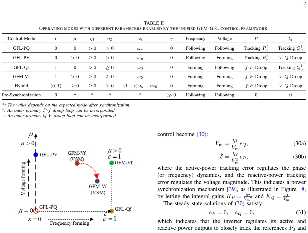
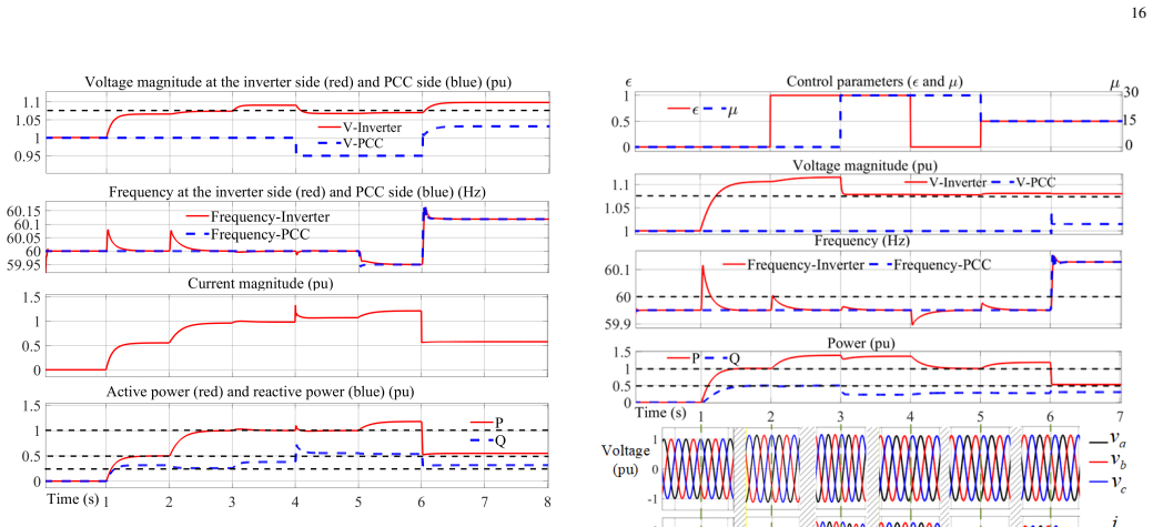
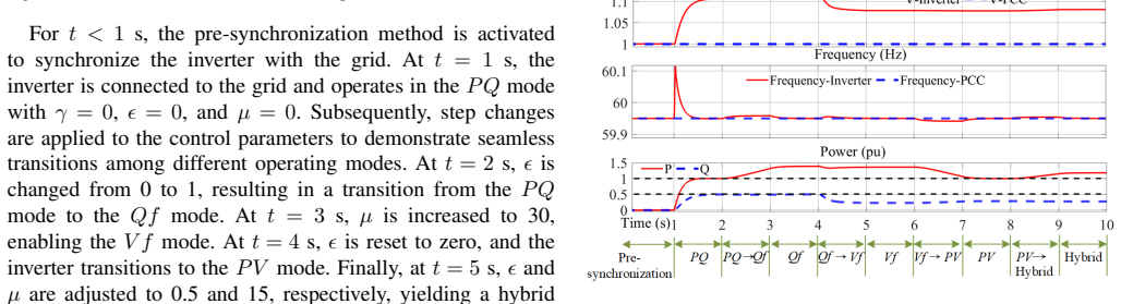
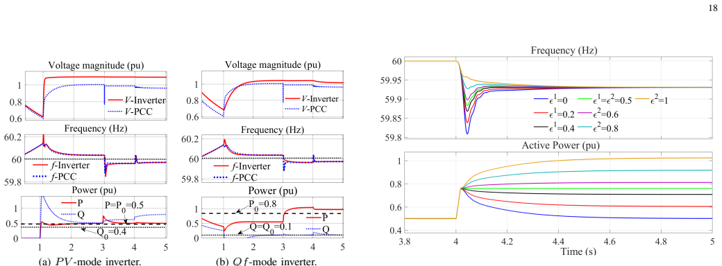
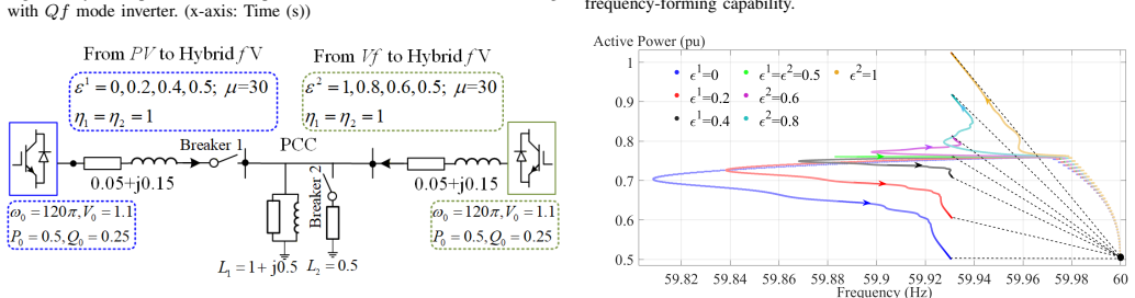
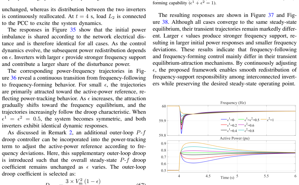
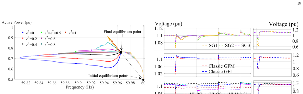
Integrating dispatchable virtual oscillator control with reference-following synchronization yields a single control structure that supports PQ, PV, Qf, Vf, and hybrid modes. Smooth pre-synchronization and transitions across these modes occur by tuning continuous parameters instead of switching discrete controllers. The framework adapts inverter dynamics to grid conditions while remaining physically interpretable, with stability verified through small-signal analysis and performance shown in EMT simulations and HIL experiments.
What carries the argument
dispatchable virtual oscillator control integrated with reference-following synchronization, which enables continuous parameter-based selection among forming and following behaviors
If this is right
- Inverters can move between PQ, PV, Qf, Vf, and hybrid modes without controller reconfiguration.
- Small-signal stability holds across the examined parameter settings for each mode.
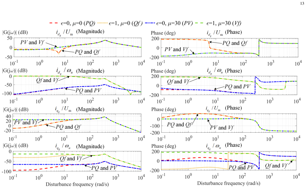
- Input-output frequency-domain behavior can be shaped directly by the same continuous parameters.
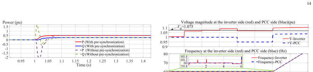
- Pre-synchronization occurs smoothly before connection to the grid in all supported modes.
Where Pith is reading between the lines
- The approach could reduce the need for multiple separate inverter controllers in microgrid or renewable installations.
- Real-time parameter adjustment might allow inverters to respond to changing grid stiffness without mode-specific redesign.
- Extension to larger networks could simplify coordination if the stability margins scale as the small-signal analysis suggests.
Load-bearing premise
The combined controls maintain stability and performance in every listed mode without unmodeled dynamics that would need extra mechanisms.
What would settle it
An EMT simulation or HIL test in which a mode transition produces instability, oscillations, or requires discrete controller changes despite the continuous parameter settings.
Figures
read the original abstract
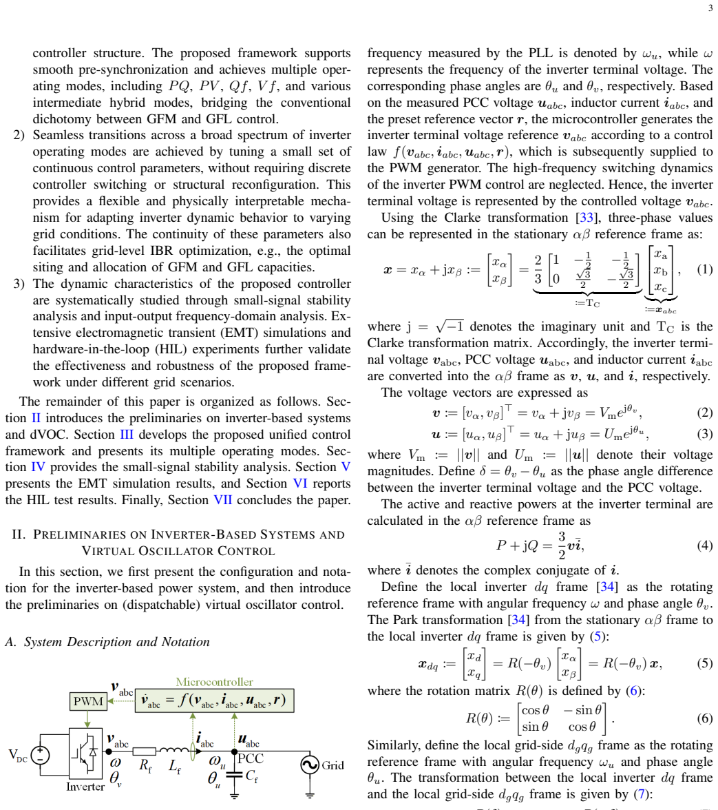
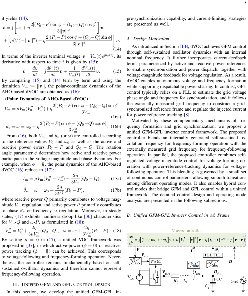
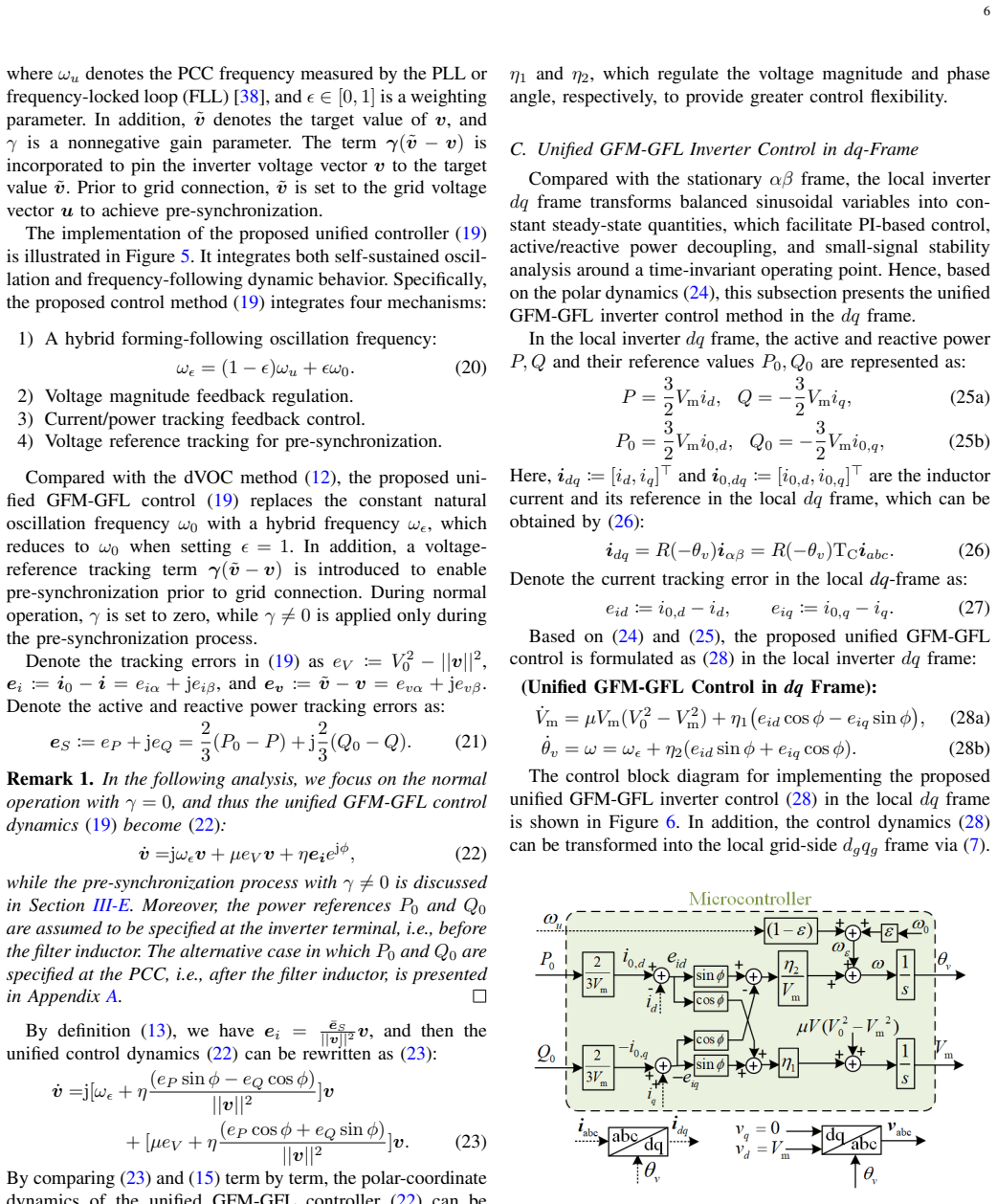
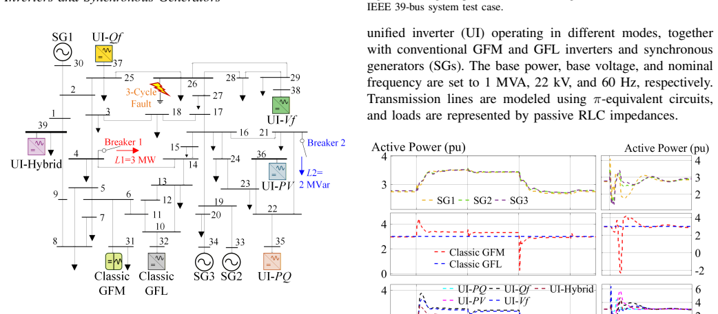
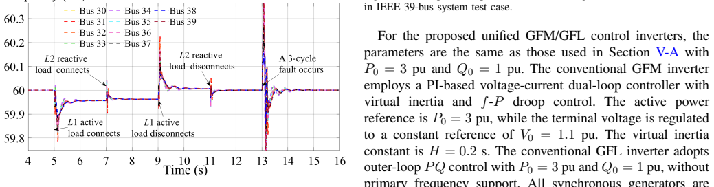
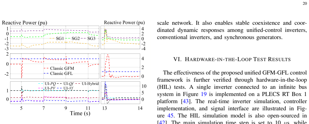
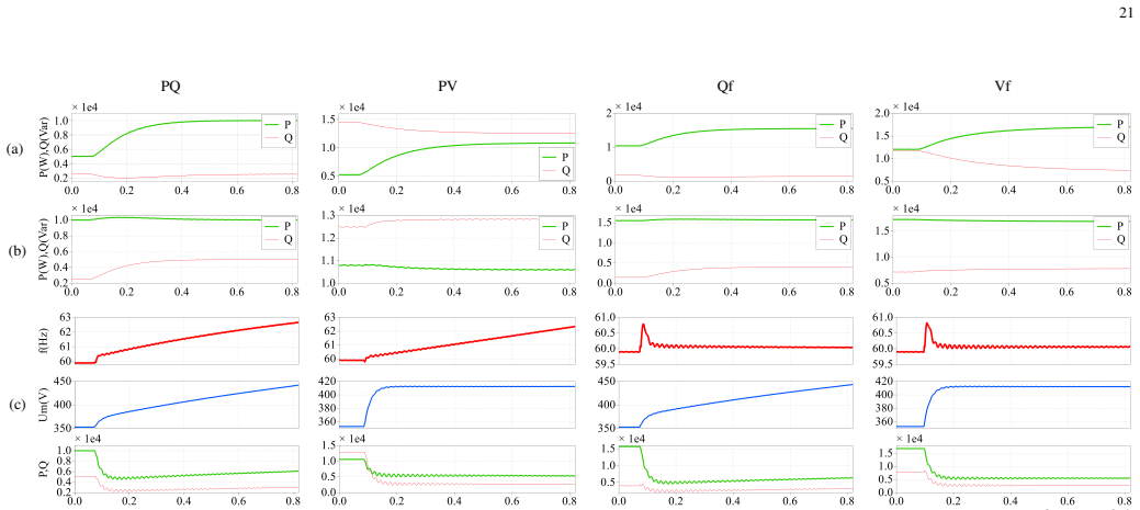
This paper proposes a novel unified control framework for achieving hybrid grid-forming (GFM) and grid-following (GFL) inverter operation by integrating dispatchable virtual oscillator control with reference-following synchronization. The proposed inverter control method supports multiple operating modes within a unified structure, including voltage- and frequency-following (PQ mode), voltage-forming and frequency-following (PV mode), voltage-following and frequency-forming (Qf mode), voltage- and frequency-forming (Vf mode), and a hybrid mode with mixed GFM and GFL behaviors. In particular, the proposed method achieves smooth pre-synchronization and enables seamless transitions across a spectrum of inverter operating modes by tuning a small set of continuous control parameters, rather than relying on discrete controller switching. This framework provides a flexible and physically interpretable approach for adapting inverter dynamics to varying grid conditions and operational requirements. The small-signal stability and input-output frequency-domain characteristics are further analyzed under different control parameter settings. The effectiveness and robustness of the proposed unified control method are demonstrated through extensive electromagnetic transient (EMT) simulations and hardware-in-the-loop (HIL) experiments.
Editorial analysis
A structured set of objections, weighed in public.
Referee Report
Summary. The paper proposes a unified inverter control framework that integrates dispatchable virtual oscillator control (dVOC) with reference-following synchronization. This structure supports PQ, PV, Qf, Vf, and hybrid GFM/GFL operating modes through continuous tuning of a small set of parameters, enabling smooth pre-synchronization and mode transitions without discrete controller switching. Small-signal stability and input-output frequency-domain analysis are performed for different parameter settings, with validation via EMT simulations and HIL experiments.
Significance. If the central claims on stability across modes and seamless transitions hold under both small- and large-signal conditions, the framework would offer a physically interpretable, flexible alternative to mode-switching approaches, potentially simplifying inverter control design for varying grid conditions. The emphasis on continuous parameters rather than discrete switching is a conceptual strength, though its practical robustness requires stronger evidence than small-signal analysis alone.
major comments (2)
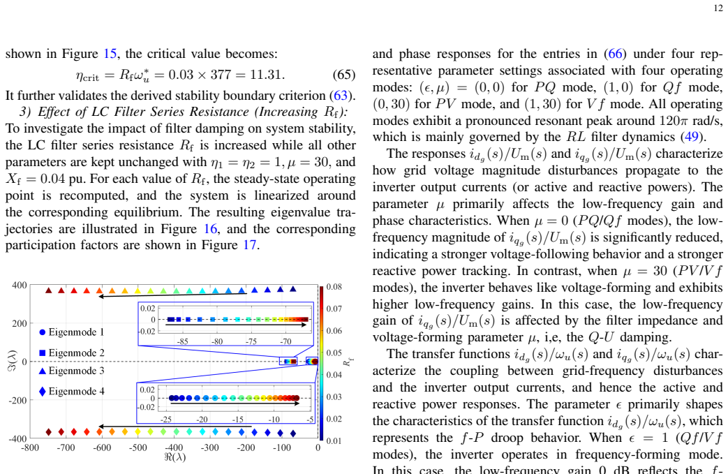
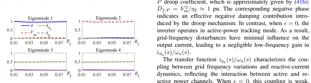
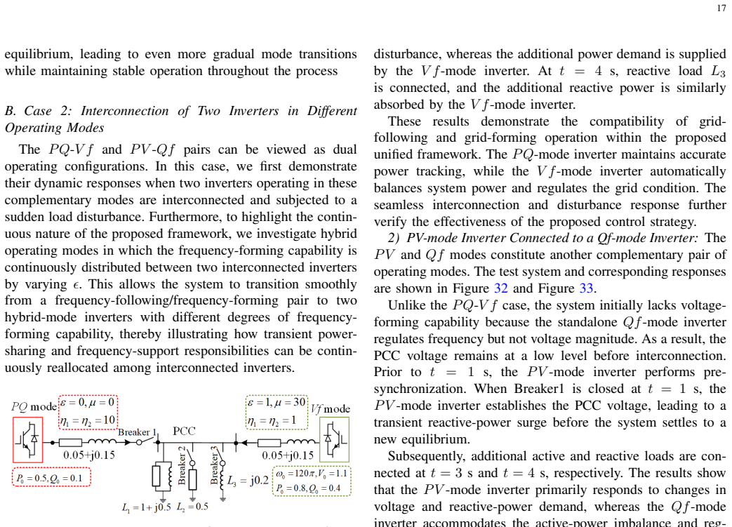
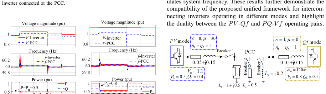
- [stability analysis section / abstract] The stability analysis (referenced in the abstract and presumably detailed in the dedicated analysis section) is restricted to small-signal linearization and frequency-domain characteristics. However, the central claim of seamless pre-synchronization and mode transitions relies on nonlinear dynamics; without Lyapunov-based large-signal analysis or explicit coverage of worst-case disturbances (e.g., grid faults during transitions), the no-additional-mechanisms assumption remains unverified.
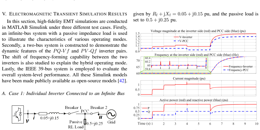
- [validation / EMT and HIL sections] The validation relies on EMT simulations and HIL experiments, but the abstract provides no quantitative metrics (error bounds, settling times, or disturbance scenarios) for the hybrid mode or transition cases. This makes it difficult to assess whether unmodeled interactions violate the unified-structure claim under realistic conditions.
minor comments (1)
- [control structure section] Notation for the control parameters and their mapping to the five operating modes should be tabulated for clarity, as the abstract refers to a 'small set' without explicit listing.
Simulated Author's Rebuttal
We thank the referee for the constructive comments on our manuscript. We address each major comment below and indicate whether revisions will be made.
read point-by-point responses
-
Referee: [stability analysis section / abstract] The stability analysis (referenced in the abstract and presumably detailed in the dedicated analysis section) is restricted to small-signal linearization and frequency-domain characteristics. However, the central claim of seamless pre-synchronization and mode transitions relies on nonlinear dynamics; without Lyapunov-based large-signal analysis or explicit coverage of worst-case disturbances (e.g., grid faults during transitions), the no-additional-mechanisms assumption remains unverified.
Authors: The manuscript centers on small-signal linearization and frequency-domain analysis to characterize local stability and input-output behavior across the continuous parameter space. The EMT simulations and HIL experiments, which incorporate the full nonlinear dynamics, explicitly demonstrate pre-synchronization, mode transitions, and operation under disturbances including grid faults. These empirical results support the claim that no additional discrete mechanisms are required. A formal Lyapunov analysis lies outside the paper's scope, which prioritizes the unified structure and its small-signal properties; the simulation evidence is sufficient to substantiate the claims. revision: no
-
Referee: [validation / EMT and HIL sections] The validation relies on EMT simulations and HIL experiments, but the abstract provides no quantitative metrics (error bounds, settling times, or disturbance scenarios) for the hybrid mode or transition cases. This makes it difficult to assess whether unmodeled interactions violate the unified-structure claim under realistic conditions.
Authors: We agree that the abstract would benefit from quantitative indicators. In the revised manuscript we will update the abstract to include representative metrics (e.g., settling times and steady-state errors) drawn from the EMT and HIL results for hybrid-mode and transition scenarios. revision: yes
Circularity Check
No circularity; derivation rests on proposed integration and external validation
full rationale
The paper defines a new unified controller by integrating dispatchable virtual oscillator control with reference-following synchronization, then tunes continuous parameters to realize PQ/PV/Qf/Vf/hybrid modes and pre-synchronization. Small-signal analysis and EMT/HIL experiments supply independent verification. No equation reduces a claimed result to a fitted input by construction, no self-citation supplies a load-bearing uniqueness theorem, and no ansatz is smuggled via prior work. The central claims therefore remain non-tautological.
Axiom & Free-Parameter Ledger
free parameters (1)
- small set of continuous control parameters
axioms (1)
- domain assumption Small-signal stability analysis and frequency-domain characteristics accurately reflect system behavior under varying parameter settings.
Reference graph
Works this paper leans on
-
[1]
Modeling, analysis and testing of autonomous operation of an inverter-based microgrid,
N. Pogaku, M. Prodanovic, and T. C. Green, “Modeling, analysis and testing of autonomous operation of an inverter-based microgrid,”IEEE Transactions on power electronics, vol. 22, no. 2, pp. 613–625, 2007
2007
-
[2]
Understanding small-signal stability of low-inertia systems,
U. Markovic, O. Stanojev, P. Aristidou, E. Vrettos, D. Callaway, and G. Hug, “Understanding small-signal stability of low-inertia systems,” IEEE Transactions on Power Systems, vol. 36, no. 5, pp. 3997–4017, 2021
2021
-
[3]
Revisiting the definition of grid-forming inverter-based resources,
A. Gupta, B. Chaudhuri, and M. O’Malley, “Revisiting the definition of grid-forming inverter-based resources,”Authorea Preprints, 2025
2025
-
[4]
Distributed coordination of grid-forming and grid-following inverters for optimal frequency control in power systems,
X. Wang and X. Chen, “Distributed coordination of grid-forming and grid-following inverters for optimal frequency control in power systems,” IEEE Transactions on Power Systems, pp. 1–16, 2026
2026
-
[5]
A virtual synchronous machine implementation for distributed control of power converters in smartgrids,
S. D’Arco, J. A. Suul, and O. B. Fosso, “A virtual synchronous machine implementation for distributed control of power converters in smartgrids,”Electric Power Systems Research, vol. 122, pp. 180–197, 2015
2015
-
[6]
A grid- compatible virtual oscillator controller: Analysis and design,
M. Lu, S. Dutta, V . Purba, S. Dhople, and B. Johnson, “A grid- compatible virtual oscillator controller: Analysis and design,” in2019 IEEE Energy Conversion Congress and Exposition (ECCE). IEEE, 2019, pp. 2643–2649
2019
-
[7]
Revisiting grid-forming and grid- following inverters: A duality theory,
Y . Li, Y . Gu, and T. C. Green, “Revisiting grid-forming and grid- following inverters: A duality theory,”IEEE Transactions on Power Systems, vol. 37, no. 6, pp. 4541–4554, 2022
2022
-
[8]
Modeling of grid-forming and grid-following inverters for dynamic simulation of large-scale distribution systems,
W. Du, F. K. Tuffner, K. P. Schneider, R. H. Lasseter, J. Xie, Z. Chen, and B. Bhattarai, “Modeling of grid-forming and grid-following inverters for dynamic simulation of large-scale distribution systems,”IEEE Trans. Power Del., vol. 36, no. 4, pp. 2035–2045, 2021
2035
-
[9]
Grid-synchronization stability of converter-based resources—an overview,
X. Wang, M. G. Taul, H. Wu, Y . Liao, F. Blaabjerg, and L. Harne- fors, “Grid-synchronization stability of converter-based resources—an overview,”IEEE Open Journal of Industry Applications, vol. 1, pp. 115– 134, 2020
2020
-
[10]
An extension of grid-forming: A frequency-following voltage-forming inverter,
C. Ai, Y . Li, Z. Zhao, Y . Gu, and J. Liu, “An extension of grid-forming: A frequency-following voltage-forming inverter,”IEEE Trans. Power Electron., vol. 39, no. 10, pp. 12 118–12 123, 2024
2024
-
[11]
A. Askarian, J. Park, and S. Salapaka. Multi-Mode Inverters: A Unified Control Design for Grid-Forming, Grid-Following, and Beyond. [Online]. Available: http://arxiv.org/abs/2410.08433
-
[12]
Seamless Switching Method Between Grid-Following and Grid-Forming Control for Renewable Energy Conversion Systems,
X. Gao, D. Zhou, A. Anvari-Moghaddam, and F. Blaabjerg, “Seamless Switching Method Between Grid-Following and Grid-Forming Control for Renewable Energy Conversion Systems,”IEEE Transactions on Industry Applications, vol. 61, no. 1, pp. 597–606, Jan. 2025
2025
-
[13]
A novel design for switchable grid-following and grid-forming control,
H. Ding, R. Kar, Z. Miao, and L. Fan, “A novel design for switchable grid-following and grid-forming control,”IEEE Transactions on Sus- tainable Energy, vol. 16, no. 2, pp. 1301–1314, 2025. 24
2025
-
[14]
Optimal control for robust dynamic performance in inverter-dominated power systems. part i: Modeling and problem formulation,
T. Ochoa, B. Chaudhuri, and M. O’Malley, “Optimal control for robust dynamic performance in inverter-dominated power systems. part i: Modeling and problem formulation,”TechRxiv, vol. 2025, no. 0807,
2025
-
[15]
Available: https://www.techrxiv.org/doi/abs/10.36227/ techrxiv.175459952.26564423/v1
[Online]. Available: https://www.techrxiv.org/doi/abs/10.36227/ techrxiv.175459952.26564423/v1
-
[16]
R. Zeng, R. Diao, F. Sun, W. Tang, J. Li, and B. Zhou, “Tran- sient stability analysis of a hybrid grid-forming and grid-following res system considering multi-mode control switching,”arXiv preprint arXiv:2508.20552, 2025
-
[17]
B. G. Odunlami and M. Netto, “Dynamic state estimation of hybrid systems: Inverters that switch between grid-following and grid-forming control schemes,”arXiv preprint arXiv:2511.13872, 2025
-
[18]
A universal controller for grid-connected voltage-source converters,
L. Harnefors, J. Kukkola, M. Routimo, M. Hinkkanen, and X. Wang, “A universal controller for grid-connected voltage-source converters,”IEEE J. Emerg. Sel. Topics Power Electron., vol. 9, no. 5, pp. 5761–5770, 2021
2021
-
[19]
Adaptive grid-synchronization based grid-forming control for voltage source converters,
H. Xiao, H. He, L. Zhang, and T. Liu, “Adaptive grid-synchronization based grid-forming control for voltage source converters,”IEEE Trans. Power Syst., vol. 39, no. 2, pp. 4763–4766, 2024
2024
-
[20]
Robust grid-forming control with active susceptance,
F. Zhao, X. Wang, Z. Zhou, Y . Sun, L. Harnefors, and T. Zhu, “Robust grid-forming control with active susceptance,”IEEE Transactions on Power Electronics, vol. 38, no. 3, pp. 2872–2877, 2023
2023
-
[21]
[Online]
REGFM C1 and REPCGFM C1 presentation September 2025 — Western Electricity Coordinating Council. [Online]. Available: https: //www.wecc.org/wecc-document/23676
2025
-
[22]
Hybrid control scheme for vsc presenting both grid-forming and grid-following capabilities,
L. A. M. Lima and E. H. Watanabe, “Hybrid control scheme for vsc presenting both grid-forming and grid-following capabilities,”IEEE Transactions on Power Delivery, vol. 37, no. 6, pp. 4570–4581, 2022
2022
-
[23]
A unified control strategy for elec- tronically interfaced distributed energy resources,
M. B. Delghavi and A. Yazdani, “A unified control strategy for elec- tronically interfaced distributed energy resources,”IEEE Transactions on Power Delivery, vol. 27, no. 2, pp. 803–812, 2012
2012
-
[24]
Unified grid-forming/following inverter control,
S. Geng and I. A. Hiskens, “Unified grid-forming/following inverter control,”IEEE Open Access J. Power Energy, vol. 9, pp. 489–500, 2022
2022
-
[25]
A virtual synchronous control for voltage-source converters utilizing dynamics of DC-link capacitor to realize self-synchronization,
L. Huang, H. Xin, Z. Wang, K. Wu, H. Wang, J. Hu, and C. Lu, “A virtual synchronous control for voltage-source converters utilizing dynamics of DC-link capacitor to realize self-synchronization,”IEEE Journal of Emerging and Selected Topics in Power Electronics, vol. 5, no. 4, pp. 1565–1577, 2017
2017
-
[26]
The electronic realization of synchronous ma- chines: Model matching, angle tracking, and energy shaping techniques,
C. Arghir and F. D ¨orfler, “The electronic realization of synchronous ma- chines: Model matching, angle tracking, and energy shaping techniques,” IEEE Transactions on Power Electronics, vol. 35, no. 4, pp. 4398–4410, 2020
2020
-
[27]
Power-balancing dual-port grid-forming power converter control for renewable integration and hybrid AC/DC power systems,
I. Suboti ´c and D. Groß, “Power-balancing dual-port grid-forming power converter control for renewable integration and hybrid AC/DC power systems,”IEEE Transactions on Control of Network Systems, vol. 9, no. 4, pp. 1949–1961, 2022
1949
-
[28]
Universal dual-port grid-forming control: Bridging the gap be- tween grid-forming and grid-following control,
——, “Universal dual-port grid-forming control: Bridging the gap be- tween grid-forming and grid-following control,”IEEE Transactions on Power Systems, vol. 39, no. 6, pp. 6861–6875, 2024
2024
-
[29]
Synthesizing virtual oscillators to control islanded inverters,
B. B. Johnson, M. Sinha, N. G. Ainsworth, F. D ¨orfler, and S. V . Dhople, “Synthesizing virtual oscillators to control islanded inverters,”IEEE Trans. Power Electron., vol. 31, no. 8, pp. 6002–6015, 2015
2015
-
[30]
Synchronization of Parallel Single-Phase Inverters With Virtual Oscillator Control,
B. B. Johnson, S. V . Dhople, A. O. Hamadeh, and P. T. Krein, “Synchronization of Parallel Single-Phase Inverters With Virtual Oscillator Control,”IEEE Trans. Power Electron., vol. 29, no. 11, pp. 6124–6138, 2014. [Online]. Available: https://ieeexplore.ieee.org/ document/6692879
-
[31]
Global phase and magnitude synchronization of coupled oscillators with application to the control of grid-forming power inverters,
M. Colombino, D. Groß, J.-S. Brouillon, and F. D ¨orfler, “Global phase and magnitude synchronization of coupled oscillators with application to the control of grid-forming power inverters,”IEEE Trans. Autom. Control, vol. 64, no. 11, pp. 4496–4511, 2019
2019
-
[32]
Virtual Oscillator Grid-Forming Inverters: State of the Art, Modeling, and Stability,
M. Lu, “Virtual Oscillator Grid-Forming Inverters: State of the Art, Modeling, and Stability,”IEEE Trans. Power Electron., vol. 37, no. 10, pp. 11 579–11 591, Oct. 2022
2022
-
[33]
Inverter parallelization for an islanded microgrid using the hopf oscil- lator controller approach with self-synchronization capabilities,
M. Li, Y . Gui, Y . Guan, J. Matas, J. M. Guerrero, and J. C. Vasquez, “Inverter parallelization for an islanded microgrid using the hopf oscil- lator controller approach with self-synchronization capabilities,”IEEE Trans. Ind. Electron., vol. 68, no. 11, pp. 10 879–10 889, 2020
2020
-
[34]
Clarke,Circuit Analysis of AC Power Systems
E. Clarke,Circuit Analysis of AC Power Systems. New York, NY , USA: Wiley, 1943, vol. 1
1943
-
[35]
Two-reaction theory of synchronous machines generalized method of analysis-part i,
R. H. Park, “Two-reaction theory of synchronous machines generalized method of analysis-part i,”Transactions of the American Institute of Electrical Engineers, vol. 48, no. 3, pp. 716–727, Jul. 1929
1929
-
[36]
Dispatchable virtual oscillator control for decentralized inverter-dominated power systems: Analysis and experiments,
G.-S. Seo, M. Colombino, I. Subotic, B. Johnson, D. Groß, and F. D ¨orfler, “Dispatchable virtual oscillator control for decentralized inverter-dominated power systems: Analysis and experiments,” in2019 IEEE Applied Power Electronics Conference and Exposition (APEC), 2019, pp. 561–566
2019
-
[37]
Synchronization and power sharing for droop-controlled inverters in islanded microgrids,
J. W. Simpson-Porco, F. D ¨orfler, and F. Bullo, “Synchronization and power sharing for droop-controlled inverters in islanded microgrids,” Automatica, vol. 49, no. 9, pp. 2603–2611, 2013
2013
-
[38]
Unified virtual oscillator control for grid- forming and grid-following converters,
M. A. Awal and I. Husain, “Unified virtual oscillator control for grid- forming and grid-following converters,”IEEE J. Emerg. Sel. Topics Power Electron., vol. 9, no. 4, pp. 4573–4586, 2021
2021
-
[39]
Multiresonant frequency-locked loop for grid synchro- nization of power converters under distorted grid conditions,
P. Rodr ´ıguez, A. Luna, I. Candela, R. Mujal, R. Teodorescu, and F. Blaabjerg, “Multiresonant frequency-locked loop for grid synchro- nization of power converters under distorted grid conditions,”IEEE Transactions on Industrial Electronics, vol. 58, no. 1, pp. 127–138, 2011
2011
-
[40]
Power-synchronization control of grid-connected voltage-source converters,
L. Zhang, L. Harnefors, and H.-P. Nee, “Power-synchronization control of grid-connected voltage-source converters,”IEEE Trans. Power Syst., vol. 25, no. 2, pp. 809–820, 2010
2010
-
[41]
Overcurrent limiting in grid-forming inverters: A comprehensive review and discussion,
N. Baeckeland, D. Chatterjee, M. Lu, B. Johnson, and G.-S. Seo, “Overcurrent limiting in grid-forming inverters: A comprehensive review and discussion,”IEEE Transactions on Power Electronics, vol. 39, no. 11, pp. 14 493–14 517, 2024
2024
-
[42]
Selective modal analysis with applications to electric power systems, part i: Heuristic introduction,
I. J. Perez-Arriaga, G. C. Verghese, and F. C. Schweppe, “Selective modal analysis with applications to electric power systems, part i: Heuristic introduction,”IEEE Transactions on Power Apparatus and Systems, vol. PAS-101, no. 9, pp. 3117–3125, 1982
1982
-
[43]
Unified GFM and GFL testcases,
X. Wang and X. Chen, “Unified GFM and GFL testcases,” https://github. com/Xiaoyang-Wang-TAMU/Unified GFM and GFL Testcases, 2026
2026
-
[44]
RT Box: Real-time simulator for power electronics,
PLEXIM GmbH, “RT Box: Real-time simulator for power electronics,”
-
[45]
Available: https://www.plexim.com/products/rt box
[Online]. Available: https://www.plexim.com/products/rt box
discussion (0)
Sign in with ORCID, Apple, or X to comment. Anyone can read and Pith papers without signing in.