REVIEW 2 major objections 5 minor 48 references
Decommissioning and Post-Irradiation Examination of the LHC Beam Dumps
T0 review · 2 major / 5 minor · reviewed 2026-08-15 · deepseek-v4-flash
Pith's one-line read After nine years of operation, the two decommissioned LHC beam dumps yielded carbon cores that remained structurally intact up to 1.5 kJ/g, with cracking confined to the extruded graphite retaining plates and their displaced rings.
desk verdict First full-scale autopsy of LHC beam dumps gives a genuinely useful, well-evidenced result, but the 'no degradation' claim for expanded graphite is slightly stronger than the measurement set can support. read the letter →
The pith
A machine-rendered reading of the paper's core claim, the machinery that carries it, and where it could break.
The reading
What carries the argument
The argument is carried by three linked elements. The first is the reconstructed deposited-energy-density field, computed with Monte Carlo simulation over the full Run 1 and Run 2 beam history including the three partial-dilution-failure events, which identifies the peak of 1.5 kJ/g near 270 cm from the upstream window and prescribes where samples were taken. The second is the mechanical explanation for the observed damage: beam impact excites vibrational modes in the vessel with accelerations up to 2000 times the acceleration of gravity, the retaining rings load the outer rim of each extruded graphite plate, and the outgassing holes act as stress concentrators from which cracks nucleate and propagate. The third is the comparison with the earlier irradiation experiment on free-to-deform expanded graphite sheets, which provides the control that isolates mechanical constraint as the factor protecting the sheets in the real dumps.
What would settle it
A controlled experiment using the same 2-mm-thick compressed expanded-graphite sheets in a nitrogen-filled stack, subjected to thousands of proton pulses with local energy density 1.5 kJ/g, and then examined by X-ray computed tomography, would settle the matter: visible interlaminar voids or local density loss in the beam-sweep region would disprove the claim that mechanical constraint prevents delamination. A future autopsy of a Run 3 dump showing such voids would do the same.
Extended reading notes
Core claim
The post-irradiation examination of both decommissioned LHC beam dumps shows no evidence of substantial material degradation in the carbon-based core materials, even where the Monte Carlo reconstructed energy density reached 1.5 kJ/g in the low-density sector. The extruded graphite plates, by contrast, showed a consistent cracking pattern with fractures originating at outgassing holes, and their retaining rings were displaced; the authors trace these failures to the dynamic response of the vessel upon beam impact, when longitudinal vibrations load the outer edges of the plates, and identify the resulting loss of compression on the expanded-graphite stack as the source of the graphite powder seen earlier. The expanded graphite sheets showed only a darkened beam-sweep pattern and minor surface oxidation with no structural or density consequences, and the isostatic graphite blocks showed no material degradation; both findings were consistent across the two dumps. The paper takes this as evidence that the delamination seen in prior irradiation of unconstrained samples was an artifact of missing surface constraints, not an inherent limit of the materials.
Load-bearing premise
The load-bearing premise is that the Monte Carlo reconstruction of the beam history and energy-density distribution, including the three partial-dilution-failure events, accurately represents the real irradiation field; if that model is biased, the quantitative link between material condition and the stated 1.5 kJ/g peak would shift, though the qualitative findings of intactness and cracking would remain.
Editorial extensions
If this is right
- The same expanded-graphite and isostatic-graphite core materials can be retained for Run 3 operation even though stored beam energy rises from 320 to 539 MJ, because a decade of service produced no beam-induced degradation in those materials.
- Graphite powder previously found inside the vessel is explained by the cracked extruded plates and their displaced rings, not by a loss of density in the beam-absorbing expanded graphite, so the absorption performance of the core was not compromised.
- Replacing the extruded graphite plates with carbon-fiber-reinforced carbon and enlarging the outgassing holes should keep the expanded-graphite stack under compression, preventing the conditions that caused the observed cracking.
- The remote wall-saw cutting and robotic coring sequence demonstrates that large, highly radioactive accelerator components can be dismantled and sampled within planned exposure limits, providing a reusable procedure for future decommissioning projects.
Reading between the lines
- If compression is what protected the expanded graphite, then any future loss of stack compression, whether from plate cracking, ring displacement, or slow relaxation, could push the material toward the delamination regime seen in unconstrained tests; monitoring ring and plate integrity may therefore be more safety-critical than the graphite grade itself.
- The 1.5 kJ/g survival threshold is established for one specific geometry, namely 2-mm-thick sheets in a nitrogen-filled compressed stack, and extrapolating it to other thicknesses, densities, or atmospheres would require testing those combinations rather than assuming a universal damage limit.
- A finite-element model of the dump's vibration during beam impact could predict which hole sizes and placements minimize stress concentration in graphite plates; this would give a quantitative design rule for future beam-intercepting devices, and the observed crack locations provide a ready validation case.
- The autopsy samples, taken along a known energy-density gradient, effectively turn the decommissioned dumps into a benchmark for energy-deposition simulations; future analyses could use the intact-versus-cracked boundary to bound the uncertainty of those simulations near 1.5 kJ/g.
Signed reviews
Editorial analysis
A structured set of objections, weighed in public.
Referee Report
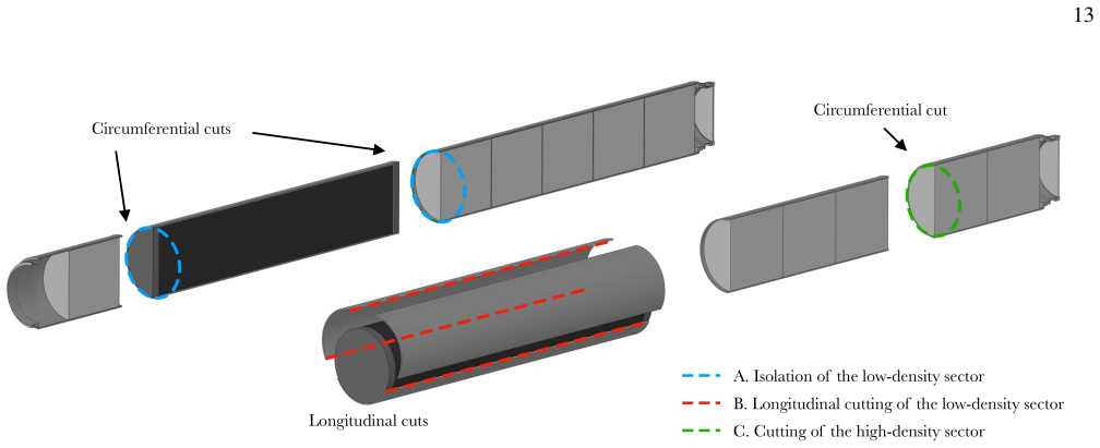
Summary. This manuscript reports the decommissioning and post-irradiation examination of the two LHC beam dumps used during Run 1 and Run 2. It covers the radiological characterization and ALARA planning, the development and selection of a remotely controlled wall-saw cutting method, the cutting sequence used to isolate the low-density and high-density sectors, and the specimen extraction and PIE of the three carbon-based core materials. The main empirical findings are that the extruded graphite retaining plates all cracked from outgassing holes and their retaining rings were displaced, while the expanded graphite sheets and isostatic graphite blocks showed no visible delamination or material degradation aside from minor surface oxidation; the paper attributes the plate cracking to the dynamic response of the device and concludes that the core survived deposited energy densities up to 1.5 kJ/g.
Significance. If the conclusions hold, this is a uniquely valuable autopsy of a high-energy, high-intensity beam-intercepting device: it is the first post-operation examination of LHC-scale beam dumps, it provides direct evidence on the condition of SIGRAFLEX expanded graphite under realistic constraints, and it has immediate engineering consequences (CFRC replacement plates, redesigned retaining rings, retention of the core-material configuration for Run 3 spares). The paper's strengths include the detailed operational record, the explicit comparison with the HiRadMat-43 experiment and Table II listing of non-comparable configurations, the use of optical CMM to quantify cracking, and the extensive radiation-protection framework with FLUKA predictions benchmarked against surveys. The central qualitative observations of intact sheets, cracked plates, and displaced rings are directly supported by photographs and measurements.
major comments (2)
- [Sec. VII A and Sec. IX] The statement in Section VII A that 'no signs of material delamination or deterioration were found' and the conclusion in Section IX that the core 'revealed no evidence of substantial material degradation' are stronger than the described measurements warrant. The failure mode that motivated the autopsy, interlaminar void formation, was originally detected in HiRadMat-43 by micro-computed tomography (Section III), but the PIE of the dump sheets used visual inspection, SEM, EDS, and FIB cross-sections only; no micro-CT, bulk-density, or porosity measurements on the 2-mm sheets are reported. Because the sheets are stacked under axial compression, a delamination void could remain closed and be invisible to surface SEM, and FIB probes only a microscopic local volume. I recommend either adding tomographic or bulk-density data for the extracted sheets, or explicitly limiting the conclusion to 'no evidence at the resolution of the applied surface and local cross-sectional techniques.'
- [Sec. VII B and Sec. IX] The 'no evidence of material degradation' claim for isostatic graphite likewise rests on SEM/EDS and Shore D hardness measurements, without density, elastic-modulus, or strength measurements; hardness alone may not detect internal cracking or porosity changes. If the central claim 'no substantial material degradation' is intended to cover all three carbon materials, this needs a qualification or supplementary bulk-property data, or the conclusion should be restricted to what the reported measurements actually probe.
minor comments (5)
- [Sec. VII A] The sentence 'three sheets were selected and catalogued every tenth of the length of the LD sector' is ambiguous; please specify the actual longitudinal positions (e.g., at 10%, 50%, and 90% of the LD sector length) and how the three selected sheets relate to the threefold peak-energy-density variation shown in Fig. 4(a).
- [Sec. IV D] The statement that 'the three blocks of HDG were placed inside a lost mold' is difficult to reconcile with the six HD blocks described in Sec. I B and the five-block downstream sector in Sec. VI C; please clarify which blocks were packaged in this container and whether the waste-packaging description refers only to a subset of the HD sectors.
- [Sec. IV B and Fig. 9] The main text says the FLUKA-SESAME results agree with RP surveys to better than 20%, but the Fig. 9 caption notes that the measurements were not originally intended for benchmark validation; please state this caveat in the main text as well, since it bears on the trustworthiness of the residual-dose predictions.
- [Sec. VII B] The Shore D hardness values (72-85) are reported without a comparison to unirradiated bulk material or to the control samples taken outside the sweep; reporting those comparisons would strengthen the claim that hardness shows no energy-density dependence.
- [Sec. VII A] The FIB cross-section thickness '65-125 nm' and the XPS information depth '¡10 nm' contain a typographical artifact ('¡' instead of '<'); fix the encoding and state whether the XPS depth is '<10 nm'.
Circularity Check
No significant circularity: the PIE findings are direct observations, and the FLUKA energy-density assignment is an independently benchmarked model rather than a fit to the autopsy outcome.
full rationale
The paper's central claim that post-irradiation examination of the carbon-based core materials revealed no substantial material degradation at energy densities up to 1.5 kJ/g rests on direct empirical observations: visual inspection, optical and SEM imaging, FIB cross-sections, EDS, XPS, Shore D hardness testing, and optical CMM scans reported in Sec. VII. The 1.5 kJ/g value is an input from FLUKA beam-energy-deposition simulations (Sec. II, Fig. 4), not a parameter fitted to the PIE outcome. The same FLUKA model was separately compared with radiation-protection surveys to better than 20% agreement (Sec. IV B), and the HiRadMat-43 and HiRadMat-56 experiments provide external comparative data. The extruded-graphite cracking and retaining-ring displacement are observed in the autopsy and attributed to the documented dynamic response; the attribution invokes CERN's own Ref. [3], but the observation itself is not derived from that reference. The comparison with HiRadMat-43 is used to explain the absence of delamination through differing surface constraints and material grade (Table II), not to derive the absence. The skeptic's concern that visual/SEM/FIB inspection may not resolve interlaminar voids, or that Shore D hardness alone does not prove absence of bulk degradation, is an evidentiary-resolution critique rather than a demonstration that a prediction reduces to its inputs. No equation or fitted parameter is renamed as a prediction, and no load-bearing uniqueness theorem is imported from prior work by the same authors. Accordingly, no circular step meets the quoted-evidence standard.
Assumptions & free parameters
assumptions (3)
- domain assumption FLUKA Monte Carlo model accurately computes energy deposition in the dump core for the Run 1 and Run 2 beam history.
- domain assumption The reconstructed beam parameters and dilution sweep patterns, including three dilution failures, reflect the true irradiation history of the dumps.
- domain assumption The material grades and dimensions of the carbon core are as documented by manufacturer datasheets and assembly drawings.
Cite this review
Pith. "Pith review of Decommissioning and Post-Irradiation Examination of the LHC Beam Dumps." pith.science (2026). https://pith.science/paper/IIKCU7UX
@misc{pith2026250504235,
  author       = {Pith},
  title        = {Pith review of: Decommissioning and Post-Irradiation Examination of the LHC Beam Dumps},
  year         = {2026},
  howpublished = {\url{https://pith.science/paper/IIKCU7UX}},
  note         = {Machine review of arXiv:2505.04235}
}
read the original abstract
The LHC beam dumps are responsible for the safe absorption of the Large Hadron Collider (LHC) particle beams. In 2018, the two 6.4-tonne beam dumps that had been in operation since the LHC's startup in 2008 were removed and replaced with upgraded versions. Endoscopic inspections of these beam dumps and experimental high-intensity proton-beam irradiation of material samples raised concerns about the structural integrity of the carbon-based materials in their cores. It was therefore decided to undertake an accelerated project of dismantling and post-irradiation examination of the removed dumps as part of a wider program of work to ensure the safe operation of the LHC beam dumps in the coming years. This paper describes the decommissioning process for the two beam dumps carried out at CERN between 2021 and 2023, covering the preparatory studies, practical challenges encountered, and solutions implemented. It details the establishment of an operational framework, including the preparation of the working environment, the development of a method for cutting the irradiated 12-mm-thick duplex stainless-steel vessel, and the cut sequencing. Additionally, the paper presents the findings derived from the post-irradiation examination of the different carbon-based core materials subjected to deposited energy densities up to 1.5 kJ/g. The extruded graphite plates within the vessel exhibited a cracking pattern, which was likely due to the dynamic response of the device upon beam impact, and their retaining rings were found to be displaced. Despite minor signs of surface deterioration, the expanded graphite sheets were intact, and the isostatic graphite blocks showed no evidence of material degradation.
Figures


Figures from the paper (23 more)






Reference graph
Works this paper leans on
- [1]
-
[2]
O. Aberle et al. , High-Luminosity Large Hadron Collider (HL-LHC) Technical Design Report (2020), CERN, Geneva (2020), Report No. CERN-2020-010, https://cds.cern.ch/record/ 2749422
work page 2020
-
[3]
J. Maestre et al., Design and behaviour of the Large Hadron Col- lider external beam dumps capable of receiving 539 MJ/dump, J. Instrum. 16, P11019
-
[4]
N. Karastathis et al. , LHC Run 3 Configuration Working Group Report (2020), CERN, Geneva (2019), https://cds.cern. ch/record/2750302
-
[5]
E. Solfiti, W. Di, A. Celotto, N. Solieri, P. A. Munoz, R. F. Ximenes, A. P. Marcone, F. X. Nuiry, A. Alvaro, F. Berto, and M. Calviani, FIB-SEM investigation and uniaxial compression of flexible graphite, Mater. Design 233, 112187 (2023)
work page 2023
-
[6]
J. Maestre, P. Andreu-Mu˜noz, C. Torregrosa, F.-x. Nuiry, K. Ker- shaw, A. Perillo-Marcone, D. Grenier, R. Franqueira, V . Riz- zoglio, A. Lechner, M. Calviani, S. E. Solfiti, F. Berto, and A. Alvaro, Sigraflex ® Studies for LHC CERN Beam Dump: Summary and Perspective, JACoW IPAC2021, 3571 (2021)
work page 2021
-
[7]
P. Andreu Mu˜noz, M. Calviani, N. Charitonidis, A. Cherif, E. Fa- rina, A. Krainer, A. Lechner, J. Maestre, F.-X. Nuiry, R. Sei- denbinder, P. Simon, and C. Torregrosa, Irradiation of Low-Z Carbon-Based Materials with 440 GeV/c Proton Beam for High Energy & Intensity Beam Absorbers: The CERN HiRadMat-56- HED Experiment, JACoW IPAC2022, 2883 (2022)
work page 2022
-
[8]
International Atomic Energy Agency, Decommissioning of Par- ticle Accelerators, Tech. Rep. (IAEA, 2020) IAEA Nuclear En- ergy Series No. NW-T-2.9
work page 2020
Show all 48 references
-
[9]
J. M. Zazula and S. P´eraire, LHC Beam Dump Design Study; 1, Simulation of Energy Deposition by Particle Cascades; Impli- cations for the Dump Core and Beam Sweeping System (1996), CERN, Geneva (1996), Report No. CERN-LHC-Project-Report- 80, https://cds.cern.ch/record/315077
1996
-
[10]
P´eraire and J
S. P´eraire and J. M. Zazula, LHC Beam Dump Design Study; Part 2, Thermal Analysis; Implications for Abort Repetition and Cooling System (1996), CERN, Geneva (1996), Report No. CERN-LHC-Project-Report-87, https://cds.cern.ch/record/ 318328
1996
-
[11]
SGL Carbon, SIGRAFINE ® R7300 - Fine-Grain Graphite Datasheet (2023), accessed: 14 March 2025
2023
-
[12]
SGL Carbon, SIGRAFLEX® APX2, APX-E, C, Z Foil - Flexi- ble Graphite Datasheet (2023), accessed: 14 March 2025
2023
-
[13]
SGL Carbon, SIGRAFINE® HLM US - Fine-Grain Graphite Datasheet (2023), accessed: 14 March 2025
2023
-
[14]
Goddard, M
B. Goddard, M. Gyr, J. Uythoven, R. Veness, and W. Weterings, LHC Beam Dumping System: Extraction Channel Layout and Acceptance (2003), CERN, Geneva (2003), Report No. CERN- LHC-Project-Report-654, https://cds.cern.ch/record/620648
2003
-
[15]
J. M. M. Ruiz, K. Kershaw, M. Calviani, D. Grenier, J. Maestre Heredia, C. L. Torregrosa Martin, L. R. Buonocore, P. Serrano Galvez, E. Matheson, J. Sola Merino, M. Guinchard, M. Ferrari, D. Senajova, C. Bertone, M. Perez Ornedo, A. In- fantino, and C. Tromel, Practical Challe...
2021
-
[16]
CERN, The official CERN FLUKA website, https://fluka.cern/ (2025)
2025
-
[17]
Ahdida et al., New capabilities of the FLUKA multi-purpose code, Front
C. Ahdida et al., New capabilities of the FLUKA multi-purpose code, Front. Phys. 9, 788253 (2022)
2022
-
[18]
Battistoni, T
G. Battistoni, T. Boehlen, F. Cerutti, P. W. Chin, L. S. Espos- ito, A. Fass `o, A. Ferrari, A. Lechner, A. Empl, A. Mairani, A. Mereghetti, P. Garcia Ortega, J. Ranft, S. Roesler, P. R. Sala, V . Vlachoudis, and G. Smirnov, Overview of the FLUKA code, Ann. Nucl. Energy 82, 10 (2015)
2015
-
[19]
I. R. Filippini, Dependability Analysis of a Safety Critical Sys- tem: The LHC Beam Dumping System at CERN , Ph.D. thesis, Pisa U. (2006)
2006
-
[20]
Carlier, A
E. Carlier, A. Antoine, P. Bobbio, G. Gr ¨awer, A. Marchand, J. Uythoven, and H. Verhagen, Design Aspects Related to the Reliability of the Control Architecture of the LHC Beam Dump Kicker Systems (2003), CERN, Geneva (2003), Report No. CERN-LHC-Project-Report-679, https://cds...
2003
-
[21]
Lechner, C
A. Lechner, C. Bracco, M. Calviani, Y . Dutheil, E. Farina, and C. Wiesner, Beam-Induced Energy Deposition on Dump Block Assembly (2021)
2021
-
[22]
Bailey and P
R. Bailey and P. Collier, Standard Filling Schemes for Vari- ous LHC Operation Modes (2003), CERN, Geneva (2003), Re- port No. LHC-PROJECT-NOTE-323, https://cds.cern.ch/record/ 691782
2003
-
[23]
Bracco, M
C. Bracco, M. J. Barnes, W. Bartmann, E. Carlier, L. Ducimetiere, M. Fraser, B. Goddard, A. Lechner, N. Magnin, M. Meddahi, A. P. Marcone, V . Senaj, J. Uythoven, and F. M. Velotti, LBDS and Injection System, in LHC Performance Work- shop (2016)
2016
-
[24]
SGL Carbon, SIGRAFLEX® TH, NH, THP, S, HP, UHP Foil - Flexible Graphite Datasheet (2023), accessed: 14 March 2025. 21
2023
-
[25]
Radiation Protection - Radiation Protection Manual Radioprotection - Manuel de radioprotection, https:// edms.cern.ch/document/335729 (2006)
CERN, Code F Rev. Radiation Protection - Radiation Protection Manual Radioprotection - Manuel de radioprotection, https:// edms.cern.ch/document/335729 (2006)
2006
-
[26]
Bozzato, P
D. Bozzato, P. Dyrcz, R. Froeschl, A. Infantino, T. Lorenzon, M. Tisi, and H. Vincke, Advanced simulation techniques for radiation protection studies at the Large Hadron Collider, Radiat. Phys. Chem. 218, 111573 (2024)
2024
-
[27]
Vincke and C
H. Vincke and C. Theis, ActiWiz 3 – An overview of the latest developments and their application, J. Phys. Conf. Ser. 1046, 012007 (2018)
2018
-
[28]
Infantino, A.-P
A. Infantino, A.-P. Bernardes, M. Calviani, G. Dumont, S. El- Idrissi, R. Mouret, C. Tromel, and H. Vincke, Radiation protec- tion challenges in the upgrade, autopsy and disposal of the LHC beam dump, Radiat. Prot. Dosim. 199, 891 (2023)
2023
-
[29]
Infantino, R
A. Infantino, R. W. Harbron, R. Mouret, P. Bertreix, A.-P. Bernardes, L. Bruno, M. Calviani, G. Dumont, S. El-Idrissi, M. Magistris, N. Menaa, C. Theis, C. Tromel, and H. Vincke, Radiological characterization for the disposal of a decommis- sioned LHC external beam dump at CER...
2023
-
[30]
Di Castro, L
M. Di Castro, L. R. Buonocore, M. Ferre, S. Gilardoni, R. Losito, G. Lunghi, and A. Masi, A dual arms robotic platform control for navigation, inspection and telemanipulation, in Proceedings of the 16th International Conference on Accelerator and Large Ex- perimental Control S...
-
[31]
CERN, REMUS: Supervisory Control and Data Acquisition (2025)
2025
-
[32]
1521 (In- ternational Atomic Energy Agency, Vienna, 2006)
International Atomic Energy Agency, Characterization, Treat- ment and Conditioning of Radioactive Graphite from Decom- missioning of Nuclear Reactors, TECDOC Series No. 1521 (In- ternational Atomic Energy Agency, Vienna, 2006)
2006
-
[33]
1647 (Inter- national Atomic Energy Agency, Vienna, 2010)
International Atomic Energy Agency, Progress in Radioactive Graphite Waste Management, TECDOC Series No. 1647 (Inter- national Atomic Energy Agency, Vienna, 2010)
2010
-
[34]
1790 (International Atomic Energy Agency, Vienna, 2016)
International Atomic Energy Agency, Processing of Irradiated Graphite to Meet Acceptance Criteria for Waste Disposal, TEC- DOC Series No. 1790 (International Atomic Energy Agency, Vienna, 2016)
2016
-
[35]
Froeschl, A method for radiological characterization based on fluence conversion coefficients, J
R. Froeschl, A method for radiological characterization based on fluence conversion coefficients, J. Phys. Conf. Ser.1046, 012006 (2018)
2018
-
[36]
KUKA Robotics, KR 120 R2700 extra HA - Industrial Robot Datasheet (2025), accessed: 14 March 2025
2025
-
[37]
Keyence Corporation, GT2-P12 Contact Distance Sensor - Tech- nical Datasheet (2025), accessed: 14 March 2025
2025
-
[38]
Hoffmann Group, Technical Datasheet - Product 22709 (2025), accessed: 14 March 2025
2025
-
[39]
Husqvarna, IPL, Husqvarna, WS 220, 2013-10, W ALL SAWS, https://www.husqvarnaconstruction.com/int/prime-equipment/ ws220/ (2018)
2018
-
[40]
Creaform, MetraSCAN - Optical 3D Scanner (2025), accessed: 14 March 2025
2025
-
[41]
Stefan and P
P. Stefan and P. Ana Teresa,Post-mortem Microscopic Examina- tion of Sigraflex Samples From TDE Dump, Tech. Rep. (CERN, 2022)
2022
-
[42]
Moreno Fern´andez, M
H. Moreno Fern´andez, M. Himmerlich, P. Costa Pinto, J. Coroa, D. Sousa, A. Baris, and M. Taborelli, The impact of h2 and n2 on the material properties and secondary electron yield of sput- tered amorphous carbon films for anti-multipacting applications, Applied Surface Scienc...
2021
-
[43]
Himmerlich, X-Ray Photoelectron Spectroscopy (XPS), Tech
M. Himmerlich, X-Ray Photoelectron Spectroscopy (XPS), Tech. Rep. (CERN, 2022)
2022
-
[44]
Dakshinamurthy, Comparative Analysis of Isostatic Graphite Samples from TDE Dump, Tech
M. Dakshinamurthy, Comparative Analysis of Isostatic Graphite Samples from TDE Dump, Tech. Rep. EDMS 3283813 (CERN,
-
[45]
Brice, LHC External Beam Dump (TDE) autopsy (2022), CERN, Geneva (2022), Report No
M. Brice, LHC External Beam Dump (TDE) autopsy (2022), CERN, Geneva (2022), Report No. CERN-PHOTO-202201-026, https://cds.cern.ch/record/2801209
2022
-
[46]
Berto, P
F. Berto, P. Lazzarin, and M. Ayatollahi, Brittle fracture of sharp and blunt v-notches in isostatic graphite under pure compression loading, Carbon 63, 101 (2013)
2013
-
[47]
Gruber, O
U. Gruber, O. ¨Ottinger, W. Baur, and L. Fischer, 12.2 carbon fiber reinforced carbon, in Industrial Carbon and Graphite Materials, Volume I (John Wiley & Sons, Ltd, 2021) Chap. 12.2, pp. 740– 824
2021
-
[2025]
version 1.0, Approved
Reviewed August 15, 2026 · model on record in the stance chip above.
Discussion (0). Continue with ORCID to comment.