REVIEW 3 major objections 6 minor 35 references
Understanding the complex morphology of a CME: multi-view analysis and numerical modeling
T0 review · 3 major / 6 minor · reviewed 2026-08-07 · deepseek-v4-flash
Pith's one-line read A single magnetic flux rope, rotated and squeezed by coronal holes and a helmet streamer, produced the two-MFR appearance and the v-shaped front of the 28 March 2022 CME.
desk verdict A plausible single-MFR explanation for a two-front CME that is honestly caveated, but the load-bearing evidence is visual field-line matching rather than the model's own density; deserves peer review with a request for synthetic white-light validation. read the letter →
The pith
A machine-rendered reading of the paper's core claim, the machinery that carries it, and where it could break.
The reading
What carries the argument
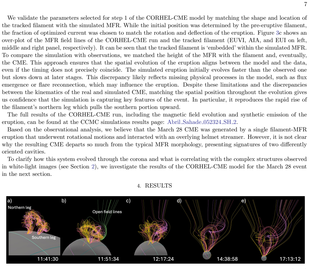
The argument is carried by a thermodynamic magnetohydrodynamic (MHD) model of the corona, initialized with a photospheric magnetogram and an eruptive magnetic flux rope whose position, height, and curvature were matched to the tracked filament. The key mechanism is asymmetric reconnection: the southern leg reconnects with the open field of the west coronal hole first, and the northern leg reconnects with the east coronal hole after being held back by the helmet streamer arcade. This differential evolution expands one end of the rope more than the other and reshapes the field lines into the structures the white-light cameras see.
What would settle it
A single in situ pass through the 28 March 2022 ejecta that detects two distinct magnetic flux ropes—two separate rotations of the magnetic field vector separated by a current sheet—would contradict the single-eruption claim. Alternatively, EUV observations showing coronal-hole footpoint brightening at the times and locations of the simulated reconnection would support it.
Extended reading notes
Core claim
The paper's central claim is that the atypical morphology of the 28 March 2022 CME was the result of the flux rope's rotation and its interaction with the ambient coronal magnetic field, not of two separate eruptions. In the model, the northern leg of a single magnetic flux rope rose fast, was obstructed by the closed field of an overlying helmet streamer, and then reconnected with the east coronal hole, producing tangled field lines that appear in white light as a U-shaped cavity and a distorted front. The southern leg reconnected earlier with the west coronal hole, losing strapping field, and expanded into a smoother, more traditional CME front. The v-shaped front seen only by the Solar Orbiter Heliospheric Imager is attributed to the orientation of upstream field lines after that reconnection. The paper concludes that a single eruption produced two apparent MFRs in coronagraph images.
Load-bearing premise
The load-bearing premise is that the model's magnetic topology—especially which leg reconnects with which coronal hole and when—matches the real event; the support is only qualitative visual matching of simulated field lines to white-light structures, with no independent magnetic-field validation.
Editorial extensions
If this is right
- White-light U-shaped cavities and concave fronts should not be treated as standalone evidence of a magnetic flux rope; they can be produced by distorted field lines from a single rope.
- A single eruption can masquerade as two CMEs or two MFR orientations in coronagraph and heliospheric images when the ambient field is asymmetric.
- The ambient coronal magnetic field, including coronal holes and helmet streamers, can be the dominant factor in a CME's early white-light shape.
- V-shaped fronts ahead of a CME can arise from reconnected or open field lines rather than from a second structure or a shock.
- Multi-view observations combined with MHD modeling can identify the magnetic origin of complex white-light features, improving space-weather interpretation.
Reading between the lines
- If this single-eruption interpretation generalizes, some 'complex' CMEs currently cataloged as multiple events may actually be one flux rope distorted by its environment; reanalyzing such events with the same model would test this.
- A quantitative metric linking white-light cavity shape to simulated magnetic topology could turn the qualitative matching here into a testable classification of CME morphology.
- The model predicts specific times and locations of coronal-hole reconnection; searching EUV data for footpoint brightening at those locations would provide an independent check on future events of this type.
Editorial analysis
A structured set of objections, weighed in public.
Referee Report
Summary. The paper investigates the 28 March 2022 CME, which appeared as a complex two-MFR structure in white-light coronagraphs and a v-shaped front in SoloHI, despite originating from a single filament eruption. Using EUV observations from SDO/AIA, STEREO/EUVI, and SolO/EUI, the authors track the erupting filament in 3D and use these measurements to initialize a CORHEL-CME thermodynamic MHD simulation. The simulation yields a single MFR whose northern and southern legs reconnect asymmetrically with the east and west coronal holes and are confined by a helmet streamer, leading to different expansion rates and field-line entangling. The authors compare the modeled field lines with LASCO, COR2, and SoloHI white-light structures and conclude that the apparent two-MFR morphology and the SoloHI v-shaped front are products of this single-MFR rotation and ambient-field interaction. They caution that U-shaped white-light cavities should not be taken as standalone MFR indicators.
Significance. If the central claim holds, the paper provides a compelling demonstration that a single CME can masquerade as two separate eruptions in coronagraph data and that apparently MFR-specific white-light signatures can be produced by non-MFR field-line structures. The study exploits an unusually good multi-viewpoint dataset (SOHO, STEREO-A, SolO) and makes the simulation publicly available through CCMC, which supports reproducibility. The two-MFR appearance and v-shaped front were not explicitly fitted; they emerged from the simulation, which is a genuine strength. The paper is admirably honest about its limitations, explicitly stating that the modeled field lines are not exact reconstructions. However, the evidence linking the modeled magnetic topology to the observed white-light morphology remains qualitative and is the main factor limiting the strength of the conclusion.
major comments (3)
- [Section 4, Figure 5] The load-bearing identification of observed white-light features (curves 1-3) with simulated structures is made by visually matching field-line plots to running-difference density images. Since white-light brightness is a line-of-sight integral of electron density, a set of field lines that appears v-shaped in a 3D rendering does not guarantee a v-shaped density enhancement after projection, background subtraction, and binning. CORHEL-CME outputs density and temperature, so the authors should compute synthetic white-light images from the simulation and compare them directly with the observations. Without such a test, alternative magnetic evolutions (e.g., two interacting flux systems, or no reconnection) might reproduce the same observed fronts equally well, and the specific claim that asymmetric reconnection with the coronal holes produced the v-shaped front is not established.
- [Section 3, paragraph beginning 'To compare the simulation with observations'] The comparison snapshots are selected by aligning heights rather than times, and the simulated eruption has different kinematics from the observed one (initially faster, then slower). This height alignment is a free parameter, and the relative timing of the reconnection events in the simulation may not correspond to the observed times at which the white-light features appear. The authors should quantify how sensitive the morphological match in Figure 5 is to the choice of alignment, or provide a time-resolved synthetic white-light sequence, to rule out the possibility that the match is an artifact of snapshot selection.
- [Section 3, paragraph beginning 'We validate the parameters selected for step 1'] Because the fraction of optimized current was chosen to match the rotation and deflection of the eruption, the model's success at reproducing those aspects is partially by construction. The paper should clarify which aspects of the morphological conclusion (the two-MFR appearance and the v-shaped front) are emergent rather than fitted, and, ideally, show that these features are robust to reasonable variations in the current fraction, the coronal heating model, and the height alignment. This would strengthen the claim that the single-MFR scenario is not an artifact of the chosen parameters.
minor comments (6)
- [Section 4, last paragraph] The word 'obvservations' should be 'observations'.
- [Section 4, Figure 5 caption] The phrase 'the simulation form SoloHI POV where the MFR core of is removed' contains two typos; it should read 'the simulation from SoloHI POV where the MFR core is removed'.
- [Section 2, Figure 1] The labels 'curve 1', 'curve 2', and 'curve 3' are introduced in the caption, but the reader must map them between panels; a single annotated composite figure or a table listing the feature names would improve clarity.
- [Section 5, first paragraph] The sentence 'Feature 1 in Figure 1 is the result of the MFR northern portion that underwent a complex evolution after an initial destabilization and fast rise obstructed by the closed overlying field belonging to the helmet streamer' is long and would benefit from being split.
- [Section 3, paragraph beginning 'We validate the parameters'] The sentence 'We validate the parameters selected for step 1 of the CORHEL-CME model by matching the shape and location of the tracked filament with the simulated MFR' could be expanded to explain what 'validate' means here, given that the current fraction is later described as chosen to match rotation and deflection.
- [Throughout] The label 'curve 3' is used both for the SoloHI v-shaped front and for a simulated field-line configuration; consider using distinct notation to avoid confusion.
Circularity Check
Partial circularity: the rotation/deflection invoked to explain the morphology is a fitted parameter, but the two-front and v-shaped structures are emergent model outputs, so the central claim retains independent content.
-
fitted input called prediction
[Section 3, CORHEL-CME initial conditions (paragraph after Figure 2)]
"While the initial position was determined by the pre-eruptive filament, the fraction of optimized current was chosen to match the rotation and deflection of the eruption."
The paper's central conclusion (Section 5) attributes the atypical white-light morphology to 'the MFR rotation and its interaction with the ambient field.' The rotation and deflection are not emergent predictions of the simulation: the free current parameter was explicitly tuned to reproduce those observed quantities from the tracked filament. Thus the causal claim 'rotation shaped the morphology' partly restates the fit. It is not fully circular because the two-MFR appearance and the SoloHI v-shaped front were not fitting targets; they arise from the subsequent MHD evolution, so the morphological interpretation retains independent content.
-
other
[Section 3, comparison method (paragraph after Figure 3c)]
"To compare the simulation with observations, we matched the height of the MFR with the filament and, eventually, the CME. This approach ensures that the spatial evolution of the eruption aligns between the model and the data, even if the timing does not precisely coincide."
The apparent agreement between model snapshots and white-light structures in Figure 5 is partly constructed: snapshots are chosen to align by height rather than time, and the correspondence between field-line renderings and density features is established by visual inspection. This does not make the morphological claim definitional, but it introduces a fitting degree of freedom in the comparison and allows the alignment procedure itself to create part of the reported match.
full rationale
The paper's central claim is that a single rotating MFR interacting with the ambient field produced the observed two-MFR appearance and SoloHI v-shaped front. The strongest circular element is explicit: the simulation's current was optimized to match the observed rotation and deflection, and the model was height-matched to the data, so the subsequent statement that rotation and ambient interaction explain the morphology is partly a restatement of fitted inputs. However, the two-front morphology and the v-shaped configuration were not fitted; they emerged from the CORHEL-CME evolution and were then visually associated with observed white-light features. The reliance on the companion paper by Sahade et al. (2025) for filament tracking and the helmet-streamer interpretation is substantial but is based on multi-view EUV observations that are externally checkable, and the paper also cites independent work for the single-eruption interpretation. The absence of synthetic white-light validation weakens the evidence but does not make the derivation circular by construction. Overall, this is a case of partial circularity in the modeling inputs and comparison procedure, not a fully self-referential derivation, so a score of 4 is appropriate.
Assumptions & free parameters
free parameters (3)
- Optimized current fraction for initial MFR =
Not stated in text; CCMC run Abril Sahade 042424 SH 1
- Height alignment between simulated MFR and observed feature =
None; manual matching
- Coronal heating model selection =
Not specified
assumptions (4)
- domain assumption The eruption contained a single magnetic flux rope, not two separate eruptions.
- domain assumption CORHEL-CME's MHD solution captures the essential magnetic interactions of the real event (rotation, reconnection with coronal holes, helmet streamer confinement).
- domain assumption The 3D tie-pointed filament positions accurately represent the erupting structure.
- ad hoc to paper Visual agreement between modeled field-line shapes and white-light density features indicates causal correspondence.
Cite this review
Pith. "Pith review of Understanding the complex morphology of a CME: multi-view analysis and numerical modeling." pith.science (2026). https://pith.science/paper/IKAYZRB7
@misc{pith2026250608820,
  author       = {Pith},
  title        = {Pith review of: Understanding the complex morphology of a CME: multi-view analysis and numerical modeling},
  year         = {2026},
  howpublished = {\url{https://pith.science/paper/IKAYZRB7}},
  note         = {Machine review of arXiv:2506.08820}
}
read the original abstract
Although all coronal mass ejections (CMEs) that propagate into the heliosphere should contain a magnetic flux rope (MFR) component, the majority do not exhibit the expected white-light MFR morphology of a leading edge plus cavity. This different appearance could be the result of distortion of the internal magnetic structure, merging with other structures, or simply projection effects. These factors complicate the interpretation of CMEs. This complexity is exemplified by a CME observed on 28 March 2022. The event originated from a single eruption, evolving as a textbook CME in the low corona but appearing as a complex two-MFR structure in white-light observations. Why? To answer this question, we performed a multi-view data and modeling analysis to describe the CME coronal evolution. The thermodynamic MHD model, CORHEL-CME, helps reveal the magnetic configuration of this CME and also reveals that the ambient field plays a crucial role in shaping the complex structure of the CME during early evolution. Our research underscores the importance of integrating multiview observations with physics-based models to gain a deeper insight into the development of complex CMEs.
Figures


Figures from the paper (2 more)

Reference graph
Works this paper leans on
-
[1]
Brueckner, G. E., Howard, R. A., Koomen, M. J., et al. 1995, SoPh, 162, 357, doi: 10.1007/BF00733434
-
[2]
Cargill, P. J., & Schmidt, J. M. 2002, Annales Geophysicae, 20, 879, doi: 10.5194/angeo-20-879-2002 11
-
[3]
Colaninno, R. C., & Vourlidas, A. 2015, ApJ, 815, 70, doi: 10.1088/0004-637X/815/1/70
-
[4]
Domingo, V., Fleck, B., & Poland, A. I. 1995, SoPh, 162, 1, doi: 10.1007/BF00733425
-
[5]
Downs, C., Linker, J. A., Miki´ c, Z., et al. 2013, Science, 340, 1196, doi: 10.1126/science.1236550
-
[6]
2023, A&A, 679, A149, doi: 10.1051/0004-6361/202346907
Stenborg, G. 2023, A&A, 679, A149, doi: 10.1051/0004-6361/202346907
-
[7]
Howard, R. A., Moses, J. D., Vourlidas, A., et al. 2008, SSRv, 136, 67, doi: 10.1007/s11214-008-9341-4
-
[8]
A., Vourlidas, A., Colaninno, R
Howard, R. A., Vourlidas, A., Colaninno, R. C., et al. 2020, A&A, 642, A13, doi: 10.1051/0004-6361/201935202
Show all 35 references
-
[9]
2015, ApJ, 813, 35, doi: 10.1088/0004-637X/813/1/35
Hutton, J., & Morgan, H. 2015, ApJ, 813, 35, doi: 10.1088/0004-637X/813/1/35
2015 doi
-
[10]
Illing, R. M. E., & Hundhausen, A. J. 1985, J. Geophys. Res., 90, 275, doi: 10.1029/JA090iA01p00275
1985 doi
- [11]
-
[12]
L., Kucera, T
Kaiser, M. L., Kucera, T. A., Davila, J. M., et al. 2008, Space Sci. Rev., 136, 5, doi: 10.1007/s11214-007-9277-0
2008 doi
-
[13]
2017, SoPh, 292, 78, doi: 10.1007/s11207-017-1098-z
Kay, C., Gopalswamy, N., Xie, H., & Yashiro, S. 2017, SoPh, 292, 78, doi: 10.1007/s11207-017-1098-z
2017 doi
-
[14]
R., Title, A
Lemen, J. R., Title, A. M., Akin, D. J., et al. 2012, SoPh, 275, 17, doi: 10.1007/s11207-011-9776-8
2012 doi
-
[15]
A., Torok, T., Downs, C., et al
Linker, J. A., Torok, T., Downs, C., et al. 2024, in Journal of Physics Conference Series, Vol. 2742, Journal of Physics Conference Series (IOP), 012012, doi: 10.1088/1742-6596/2742/1/012012
2024 doi
-
[16]
A., & Miki´ c, Z
Lionello, R., Linker, J. A., & Miki´ c, Z. 2009, ApJ, 690, 902, doi: 10.1088/0004-637X/690/1/902 Mac Cormack, C., Shaik, S. B., Hess, P., Colaninno, R., &
2009 doi
-
[17]
2025, SoPh, 300, 54, doi: 10.1007/s11207-025-02463-7
Nieves-Chinchilla, T. 2025, SoPh, 300, 54, doi: 10.1007/s11207-025-02463-7
2025 doi
-
[18]
E., Pomoell, J., Palmroos, C., et al
Morosan, D. E., Pomoell, J., Palmroos, C., et al. 2024, A&A, 683, A31, doi: 10.1051/0004-6361/202347873 M¨ uller, D., St. Cyr, O. C., Zouganelis, I., et al. 2020, A&A, 642, A1, doi: 10.1051/0004-6361/202038467
2024 doi
-
[19]
2020, SSRv, 216, 131, doi: 10.1007/s11214-020-00757-9
Patsourakos, S., Vourlidas, A., T¨ or¨ ok, T., et al. 2020, SSRv, 216, 131, doi: 10.1007/s11214-020-00757-9
2020 doi
-
[20]
D., Thompson, B
Pesnell, W. D., Thompson, B. J., & Chamberlin, P. C. 2012, SoPh, 275, 3, doi: 10.1007/s11207-011-9841-3
2012 doi
-
[21]
M., et al
Podladchikova, T., Jain, S., Veronig, A. M., et al. 2024, A&A, 691, A344, doi: 10.1051/0004-6361/202451777
2024 doi
-
[22]
M., Dickson, E
Purkhart, S., Veronig, A. M., Dickson, E. C. M., et al. 2023, A&A, 679, A99, doi: 10.1051/0004-6361/202346354
2023 doi
-
[23]
A., Miki´ c, Z., et al
Riley, P., Linker, J. A., Miki´ c, Z., et al. 2003, Journal of Geophysical Research (Space Physics), 108, 1272, doi: 10.1029/2002JA009760
2003 doi
-
[24]
2020, A&A, 642, A8, doi: 10.1051/0004-6361/201936663 Rodr ´ ıguez-Garc ´ ıa, L., Nieves-Chinchilla, T., G´ omez-Herrero, R., et al
Rochus, P., Auch` ere, F., Berghmans, D., et al. 2020, A&A, 642, A8, doi: 10.1051/0004-6361/201936663 Rodr ´ ıguez-Garc ´ ıa, L., Nieves-Chinchilla, T., G´ omez-Herrero, R., et al. 2022, A&A, 662, A45, doi: 10.1051/0004-6361/202142966
2020 doi
-
[25]
2024,, 1 Zenodo, doi: 10.5281/zenodo.13951841
Sahade, A. 2024,, 1 Zenodo, doi: 10.5281/zenodo.13951841
2024 doi
-
[26]
A., & C´ ecere, M
Sahade, A., Vourlidas, A., Balmaceda, L. A., & C´ ecere, M. 2023, ApJ, 953, 150, doi: 10.3847/1538-4357/ace420
2023 doi
-
[27]
2025, ApJ, 978, 41, doi: 10.3847/1538-4357/ad96ba
Sahade, A., Vourlidas, A., & Mac Cormack, C. 2025, ApJ, 978, 41, doi: 10.3847/1538-4357/ad96ba
2025 doi
-
[28]
H., Schou, J., Bush, R
Scherrer, P. H., Schou, J., Bush, R. I., et al. 2012, SoPh, 275, 207, doi: 10.1007/s11207-011-9834-2
2012 doi
-
[29]
2011, ApJS, 194, 33, doi: 10.1088/0067-0049/194/2/33
Thernisien, A. 2011, ApJS, 194, 33, doi: 10.1088/0067-0049/194/2/33
2011 doi
-
[30]
Thernisien, A., Vourlidas, A., & Howard, R. A. 2009, SoPh, 256, 111, doi: 10.1007/s11207-009-9346-5
2009 doi
-
[31]
Thernisien, A. F. R., Howard, R. A., & Vourlidas, A. 2006, ApJ, 652, 763, doi: 10.1086/508254
2006 doi
-
[32]
S., Downs, C., Miki´ c, Z., et al
Titov, V. S., Downs, C., Miki´ c, Z., et al. 2018, ApJL, 852, L21, doi: 10.3847/2041-8213/aaa3da T¨ or¨ ok, T., Downs, C., Linker, J. A., et al. 2018, ApJ, 856, 75, doi: 10.3847/1538-4357/aab36d
2018 doi
-
[33]
2019, A&A, 627, A111, doi: 10.1051/0004-6361/201834702
Verbeke, C., Pomoell, J., & Poedts, S. 2019, A&A, 627, A111, doi: 10.1051/0004-6361/201834702
2019 doi
-
[34]
2014, Plasma Physics and Controlled Fusion, 56, 064001, doi: 10.1088/0741-3335/56/6/064001
Vourlidas, A. 2014, Plasma Physics and Controlled Fusion, 56, 064001, doi: 10.1088/0741-3335/56/6/064001
2014 doi
-
[35]
R., Tarbell, T
Wuelser, J.-P., Lemen, J. R., Tarbell, T. D., et al. 2004, in Society of Photo-Optical Instrumentation Engineers (SPIE) Conference Series, Vol. 5171, Telescopes and Instrumentation for Solar Astrophysics, ed. S. Fineschi & M. A. Gummin, 111–122, doi: 10.1117/12.506877
2004 doi
Reviewed August 7, 2026 · model on record in the stance chip above.
Discussion (0). Continue with ORCID to comment.