REVIEW 4 major objections 6 minor 29 references
Coupling Effects in Multi-Stage Laser Wake-field Acceleration of Electrons
T0 review · 4 major / 6 minor · reviewed 2026-08-14 · deepseek-v4-flash
Pith's one-line read Self-focusing turns a 700 µm bunch into a 20 µm wake rider
desk verdict A real staged-coupling observation, but the Budker–Bennett explanation leans on simulations that do not match the measured beam. read the letter →
The pith
A machine-rendered reading of the paper's core claim, the machinery that carries it, and where it could break.
The reading
What carries the argument
The central mechanism is the Budker–Bennett effect of electron-beam self-focusing in plasma. As a relativistic electron bunch enters low-density plasma, its radial field evacuates some background plasma electrons while the heavier beam electrons remain in place; the resulting positive ion column exerts a transverse focusing force on the beam. The quantitative condition used in the paper is that focusing occurs when the plasma density perturbation satisfies $(N_i-N_e)>N_B/\gamma_0^2$, which for a 10 pC, 10 µm ball beam means $\Delta N\sim10^{14}$ cm$^{-3}$, a value available even in a $10^{17}$ cm$^{-3}$ pre-plasma. This mechanism, rather than the solenoid or geometrical emittance, is what carries the bunch from its ~0.7 mm diameter to the ~20 µm wake size and makes the measured coupling efficiency possible.
What would settle it
Measure the transverse profile of the 10 MeV bunch just before it enters the booster wake, with and without the booster gas jet and laser; if the bunch remains roughly 0.7 mm wide at the wake entrance while 10–90% of its charge is still modulated, the self-focusing explanation is wrong. Alternatively, run the PIC code from the experimental initial condition (0.7 mm diameter, 1.6 pC, 3% energy spread) and check whether the bunch is compressed to near 20 µm over the measured pre-plasma length; failure to compress would falsify the claim.
Extended reading notes
Core claim
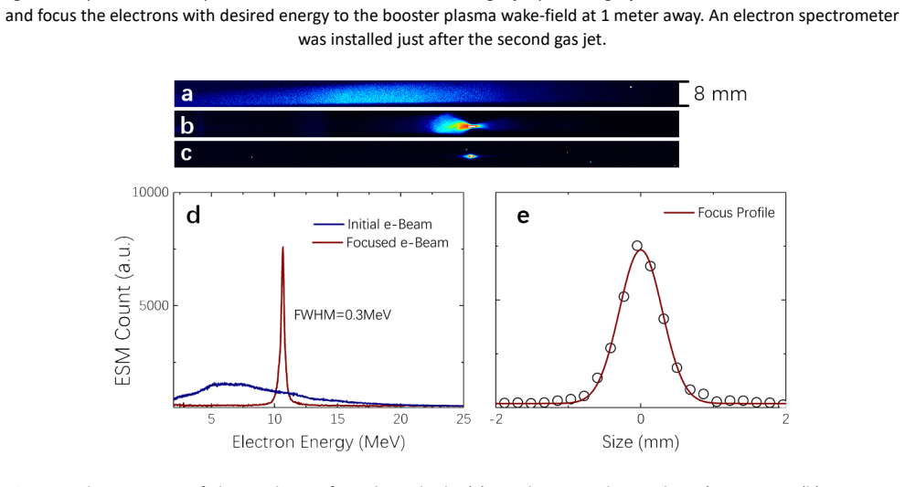
On the paper's own terms, the discovery is that temporal and spatial coupling between an injector stage and a booster stage in a laser wakefield accelerator is governed not by the geometric emittance of the injected bunch but by cumulative plasma self-focusing of the bunch in the low-density pre-plasma ahead of the booster. A 10 MeV, 1.6 pC bunch with ~3% energy spread and <0.7 mm transverse size enters a booster with a ~20 µm focal spot; despite the size mismatch, 10–90% of the electrons are captured and modulated by the wake. The explanation is the Budker–Bennett condition $(N_i-N_e)>N_B/\gamma_0^2$: with a beam density of roughly $6\times10^{16}$ cm$^{-3}$ and $\gamma_0\approx20$, an excess ion density of only about $10^{14}$ cm$^{-3}$ suffices to focus the beam, so even a dilute pre-plasma from the gas jet can compress the bunch to wake size. Multidimensional PIC simulations reproduce the focusing in uniform, convex, and concave plasma profiles and agree with the observed energy modulation of the beam.
Load-bearing premise
The explanation depends on an unmeasured assumption, from a private communication, that the gas in front of the booster forms a long low-density plasma that can squeeze the electron bunch from ~0.7 mm down to the ~20 µm wake size; the supporting simulations start from a 50 µm, 10 pC beam rather than the experimental 0.7 mm, 1.6 pC beam, so the compression across the full size gap is assumed rather than demonstrated.
Editorial extensions
If this is right
- If the claim is correct, multistage laser wakefield accelerators do not require sub-100 µm transverse focusing and transport of injected bunches; self-focusing in a pre-plasma can relax the beamline tolerances.
- Transverse coupling is not the limiting factor in staged schemes: the longitudinal bunch length, ~70–100 µm, still exceeds the ~10 µm wake wavelength, so most electrons sit near zero-field phases and gain little net energy.
- Injection-efficiency estimates based only on spot-size ratios should be replaced by models that include plasma-density-gradient self-focusing in the region before the booster.
- Because convex density channels give the strongest focusing in the simulations, shaping the pre-plasma profile offers a practical control knob for booster design.
- Marking beam electrons separately from plasma electrons in PIC simulations gives a workable method for isolating and predicting bunch dynamics in staged acceleration.
Reading between the lines
- The same self-focusing mechanism should scale to higher-charge, higher-energy bunches, which would let staged accelerators accept relatively large-emittance injector beams and still couple efficiently into small wakes.
- A direct experimental test would be to image the bunch transversely just before the booster, with and without the low-density gas present: observing no compression to near-wake size would falsify the paper's explanation.
- The effect probably applies to any dense relativistic bunch travelling through ambient plasma, including halo or dark-current electrons, so future beamlines may need to design for it rather than assume free-space transport.
Signed reviews
Editorial analysis
A structured set of objections, weighed in public.
Referee Report
Summary. The manuscript reports an experimental study of electron coupling between a laser-plasma-cathode injector and a booster stage in a two-stage laser wakefield accelerator. The injector produces ~1.6 pC, ~10 MeV electron bunches with energy spread <3%, focused to <0.7 mm at the booster position about 1.4 m downstream. The booster laser generates a wakefield with a spot size of ~20 µm and period ~10 µm. The authors observe that 10–90% of the injected electrons are modified by the booster, which they attribute to Budker–Bennett self-focusing of the bunch in a low-density pre-plasma (n_e ~ 10^17 cm^-3, several mm long) in front of the booster gas jet. They support this with PIC simulations of a 50 µm, 10 pC beam focusing in such a plasma and with simulations of the interaction of a 70 µm long bunch with the wakefield. The paper concludes that the measured coupling is caused by the Budker–Bennett effect and that the simulation results agree well with the measurements.
Significance. If the claimed mechanism is correct, the result would be significant for the practical design of staged LWFA, because it would show that beam self-focusing in a low-density pre-plasma can greatly relax the alignment and spot-size requirements for coupling between stages. The paper also demonstrates careful experimental characterization of the injector beam and a two-beam synchronization scheme with low jitter. However, the significance is conditional on the validity of the mechanism attribution, which, as detailed below, is not established by the presented evidence.
major comments (4)
- [Results, Fig. 4] The PIC simulation used to support the Budker–Bennett focusing mechanism uses an electron beam with 50 µm diameter and 10 pC total charge, whereas the experimental beam has <0.7 mm FWHM diameter and ~1.6 pC. For comparable bunch lengths, this corresponds to a beam density difference of approximately 10^3 (N_B ~ 5×10^14 cm^-3 for the simulated beam versus N_B ~ 3×10^11 cm^-3 for the experimental beam). Because the focusing force in Eq. (1) is proportional to N_B after plasma-electron evacuation, the focusing time scales roughly as 1/√N_B. The simulation shows focusing within 30 ps (about 9 mm of propagation), but for the experimental beam density the same mechanism would require about a factor of 30 longer time, i.e., ~1 ns, corresponding to ~30 cm of propagation at the speed of light, far exceeding the 'several mm' pre-plasma. No scaling argument or simulation with experimental parameters is provided to bridge this gap. The central attribution of the observed coupling to Budker–Bennett focusing is therefore not demonstrated.
- [Results, paragraph on pre-plasma; Ref. 27] The existence, density, and length of the pre-plasma are based on a private communication (Ref. 27) and are not independently verified. The entire mechanism relies on the assumption that the gas jet has a 'long, several mm front part with relatively low gas density N ~ 10^17 cm^-3'. Since the required focusing distance depends critically on both the beam density and the plasma density, the authors should either provide a direct measurement of the pre-plasma density profile or demonstrate that the conclusion is insensitive to plausible variations in these parameters. In its current form, the evidence for the mechanism rests on an unverified external input.
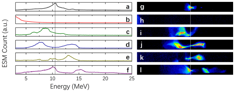
- [Discussion, Figs. 3 and 6] The text states that the number of electrons with modified energy after passing through the booster varied from 10% to 90% of the initial charge and attributes this to efficient coupling. However, the simulation in Fig. 6 and the accompanying text say that 'only small amount of electrons are further accelerated and, correspondingly, a small amount of electron are decelerated. Most of electrons have near the same energy as before the interaction.' These statements are not reconciled. If most electrons are unmodified, the measured 10–90% 'modified' fraction cannot be a straightforward measure of efficient coupling. The authors should define precisely what is counted as 'modified' in the experiment, how this fraction is extracted from the spectrometer images, and what the corresponding fraction in the simulation is.
- [Abstract, Results, Discussion] The abstract claims that 'measured characteristics of electron beams modified by the booster wake field agree well with those obtained by multidimensional particle-in-cell simulations,' but no quantitative comparison is shown. The simulations of the wakefield interaction (Fig. 6) are performed for plasma densities of 3×10^19 and 3×10^18 cm^-3, while the experimental booster density is not specified; the text says only that the lower density is closer to the measurement. No overlay of simulated and measured spectra, nor any statistical metric, is presented. The claim of agreement is therefore not supported.
minor comments (6)
- [Introduction, after Eq. (1)] The text says 'Poison equation'; this should be 'Poisson equation'.
- [Throughout] The spelling of the effect is inconsistent: 'Bennet-Budker' and 'Budker-Bennett' are both used. Please use one spelling consistently.
- [Results and Methods] The distance between injector and booster is given as L ~ 1.4 m in the Results section but as '1 meter away' in the Methods section. Please clarify the actual distance.
- [Abstract] The sentence 'characterization of the coupling is performed with dense, stable, a narrow energy band <3% and energy selectable electron beams' is grammatically incomplete and should be rewritten.
- [Fig. 2 caption] The caption says 'form the cathode'; this should be 'from the cathode'.
- [Discussion] The beam size at the booster is given as '<0.7 mm FWHM' in the Results and Methods, but 'less than 800 µm' in the Discussion. Please make these consistent.
Circularity Check
No significant circularity: the Budker–Bennett focusing argument is derived from a standard equation, and the experimental claims are compared against independent PIC simulations rather than being defined by the inputs.
full rationale
The paper's central derivation is the Budker–Bennett focusing condition, obtained from the Poisson equation in the beam frame (Eq. 1). This is a first-principles electrodynamic result, with no parameter fitted to the measured spectra. The measured 10–90% coupling efficiency is not used as an input to the model; instead, the paper attributes the observed coupling to the Budker–Bennett effect and supports this with multidimensional PIC simulations shown in Figs. 4–6. The PIC runs are presented in the paper, not imported solely through citations. The cited prior work by the same authors (Ref. 23 for the plasma-cathode beam characterization method and Ref. 29 for the PIC code FPlaser3D) is not load-bearing for the physical conclusion: the beam properties are measured in this experiment and the simulations are described and displayed directly. Ref. 27, a private communication, supplies the pre-plasma density/length parameters, but this is external information, not a self-citation, and it is not used to define the outcome. The main weakness is evidential mismatch: the PIC beam (50 µm, 10 pC) is much denser than the transported experimental bunch (0.7 mm, ~1.6 pC), so the extrapolation is not fully demonstrated. That is a correctness or evidence concern, not circularity. No equation or fitted parameter is reused as a 'prediction,' and no uniqueness claim is imported from the authors' prior work. Therefore the derivation chain is self-contained with respect to circularity.
Assumptions & free parameters
free parameters (3)
- PIC simulation beam diameter =
50 µm (vs ~0.7 mm experiment)
- PIC simulation beam charge =
10 pC (vs 1.6 pC experiment)
- Pre-plasma density =
~1e17 cm^-3 (simulations use 3e17 cm^-3)
assumptions (3)
- domain assumption Budker-Bennett focusing condition (Ni - Ne) > NB / gamma0^2 holds for the experimental beam and plasma parameters
- domain assumption The booster gas jet has a long, several-mm low-density front region
- ad hoc to paper PIC results obtained with a 50 µm, 10 pC beam extrapolate to the 0.7 mm, 1.6 pC experimental beam
Cite this review
Pith. "Pith review of Coupling Effects in Multi-Stage Laser Wake-field Acceleration of Electrons." pith.science (2026). https://pith.science/paper/J2BQLH3B
@misc{pith2026190801440,
  author       = {Pith},
  title        = {Pith review of: Coupling Effects in Multi-Stage Laser Wake-field Acceleration of Electrons},
  year         = {2026},
  howpublished = {\url{https://pith.science/paper/J2BQLH3B}},
  note         = {Machine review of arXiv:1908.01440}
}
read the original abstract
Staging laser wake-field acceleration is considered as a necessary technique for developing full-optical jitter-free electron accelerators. Splitting of the acceleration length into several technical parts with their lengths smaller than the dephasing length and with independent laser drivers allows generation of stable, reproducible acceleration fields. Temporal and spatial coupling of pre-accelerated electron bunches for their injection in the acceleration phase of a successive laser pulse wake field is the key part of the staging laser-driven acceleration. Here, characterization of the coupling is performed with dense, stable, a narrow energy band <3% and energy selectable electron beams with charges ~1.6 pC and energy ~10 MeV generated from a laser plasma cathode. Cumulative focusing of electron bunches in a low density pre-plasma, exhibiting the Budker- Bennett effect, is shown to result in the efficient injection of electrons even with a long distance between the injector and the booster in the laser pulse wake. Measured characteristics of electron beams modified by the booster wake field agree well with those obtained by multidimensional particle-in-cell simulations.
Figures

Figures from the paper (1 more)

Reference graph
Works this paper leans on
-
[1]
Tajima, T & Dawson, J. M. Laser Electron Accelerator. Phys. Rev. Lett. 43, 267, (1979)
work page 1979
-
[2]
Short pulse laser interaction with matter
Gibbon, P . Short pulse laser interaction with matter. (World Scientific, 2005)
work page 2005
-
[3]
Mangles, S. P . D., Murphy, C. D., Najmudin, Z., Thomas, A. G. R., Collier, J. L., Dangor, A. E., Divall, E. J., Foster, P . S., Gallacher, J. G., Hooker, C. J., Jaroszynski, D. A., Langley, A. J., Mori, W. B., Norreys, P . A., Tsung, F. S., Viskup, R., Walton, B. R. & Krushelnick, K. Monoenergetic beams of relativistic electrons from intense laser–plasma...
work page 2004
-
[4]
Geddes, C. G. R., Toth, Cs., Tilborg, J. van, Esarey, E., Schroeder, C. B., Bruhwiler, D., Nieter, C., Cary, J. & Leemans, W. P . High-quality electron beams from a laser wakefield accelerator using plasma-channel guiding. Nature 431, 538 (2004)
work page 2004
-
[5]
, Pukhov, A., Kiselev, S., Gordienko, S., Lefebvre, E., Rousseau, J.-P
Faure, J., Glinec, Y. , Pukhov, A., Kiselev, S., Gordienko, S., Lefebvre, E., Rousseau, J.-P. , Burgy, F., & Malka, V. A laser– plasma accelerator producing monoenergetic electron beams. Nature 431, 541 (2004)
work page 2004
-
[6]
Tokita, S., Hashida, M., Inoue, S., Nishoji, T., Otani, K. & Sakabe, S. Single-Shot Femtosecond Electron Diffraction with Laser-Accelerated Electrons: Experimental Demonstration of Electron Pulse Compression. Phys. Rev. Lett. 105, 215004 (2010)
work page 2010
-
[7]
He, Z. H., Thomas, A. G. R., Beaurepaire, B., Nees, J. A., Hou, B., Malka, V., Krushelnick, K. & Faure, J. Electron diffraction using ultrafast electron bunches from a laser-wakefield accelerator at kHz repetition rate. Appl. Phys. Lett. 102, 064104 (2013)
work page 2013
-
[8]
Cole, J. M., Wood, J. C., Lopes, N. C., Poder, K., Abel, R. L., Alatabi, S., Bryant, J. S. J., Jin, A., Kneip, S., Mecseki, K., Symes, D. R., Mangles, S. P . D. & Najmudin, Z. Laser-wakefield accelerators as hard x-ray sources for 3D medical imaging of human bone. Scientific Reports 5, 13244 (2015)
work page 2015
Show all 29 references
-
[9]
& Horioka, K., Optical guidance of terrawatt laser pulses by the implosion phase of a fast Z-pinch discharge in a gas-filled capillary
Hosokai, T., Kando, M., Dewa, H., Kotaki, H., Kondo, S., Hasegawa, N., Nakajima, K. & Horioka, K., Optical guidance of terrawatt laser pulses by the implosion phase of a fast Z-pinch discharge in a gas-filled capillary. Opt. Lett. 25, 10 (2000)
2000
-
[10]
& Uesaka, M
Hosokai, T., Kinoshita, K., Zhidkov, A., Maekawa, A., Yamazaki, A. & Uesaka, M. Effect of External Static Magnetic Field on the Emittance and Total Charge of Electron Beams Generated by Laser-Wakefield Acceleration. Phys. Rev. Lett. 97, 075004 (2006)
2006
-
[11]
P ., Nagler, B., Gonsalves, A
Leemans, W. P ., Nagler, B., Gonsalves, A. J., Toth, Cs., Nakamura, K., Geddes, C. G. R., Esarey, E., Schroeder, C. B. & Hooker, S. M. GeV electron beams from a centimetre-scale accelerator. Nat. Phys. 2, 696 (2006)
2006
-
[12]
M., Geissler, M., Shen, B., Krausz, F., Karsch, S
Buck, A., Wenz, J., Xu, J., Khrennikov, K., Schmid, K., Heigoldt, M., Mikhailova, J. M., Geissler, M., Shen, B., Krausz, F., Karsch, S. & Veisz, L. Shock-Front Injector for High-Quality Laser-Plasma Acceleration. Phys. Rev. Lett. 110, 185006 (2013)
2013
-
[13]
P ., Gonsalves, A
Leemans, W. P ., Gonsalves, A. J., Mao, H.-S., Nakamura, K., Benedetti, C., Schroeder, C. B., Toth, Cs., Daniels, J., Mittelberger, D. E., Bulanov, S. S., Vay, J.-L., Geddes, C. G. R. & Esarey, E. Multi-GeV Electron Beams from Capillary- Discharge-Guided Subpetawatt Laser Puls...
2014
-
[14]
& Kodama, R
Nakanii, N., Hosokai, T., Iwasa, K., Masuda, S., Zhidkov, A., Pathak, N., Nakahara, H., Mizuta, Y ., Takeguchi, N. & Kodama, R. Transient magnetized plasma as an optical element for high power laser pulses. Phys. Rev. ST Accel. Beams 18, 021303 (2015)
2015
-
[15]
& Tajima, T
Kando, M., Masuda, S., Zhidkov, A., Yamazaki, A., Kotaki, H., Kondo, S., Homma, T., Kanazawa, S., Nakajima, K., Hayashi, Y ., Mori, M., Kiriyama, H., Akahane, Y ., Inoue, N., Ueda, H., Nakai, Y ., Tsuji, K., Yamamoto, Y ., Yamakawa, K., Koga, J., Hosokai, T., Uesaka, M. & Taji...
2005
-
[16]
Weathersby, S. P . et al. Mega-electron-volt ultrafast electron diffraction at SLAC National Accelerator Laboratory. Rev. Sci. Inst. 86, 073702 (2015)
2015
-
[17]
& Umstadter, D
Golovin, G., Banerjee, S., Chen, S., Powers, N., Liu, C., Yan, W., Zhang, J., Zhang, P ., Zhao, B. & Umstadter, D. Control and optimization of a staged laser-wakefield accelerator. Nucl. Ins. Meth. A (NIMA) 830, 375 (2016)
2016
-
[18]
van, Benedetti, C., Geddes, C
Steinke, S., Tilborg, J. van, Benedetti, C., Geddes, C. G. R., Schroeder, C. B., Daniels, J., Swanson, K. K., Gonsalves, A. J., Nakamura, K., Matlis, N. H., Shaw, B. H., Esarey E. & Leemans, W. P . Multistage coupling of independent laser- plasma accelerators. Nature 530, 190 (2016)
2016
-
[19]
Siegman, A. E. Lasers. (University Science Books, Mill Valley, CA, 1986)
1986
-
[20]
Budker, G. I. Relativistic stabilized electron beam. The Soviet Journal of Atomic Energy 1, 673 (1956)
1956
-
[21]
Bennett, W. H. Self-Focusing Streams. Phys. Rev. 98, 1584 (1955)
1955
-
[22]
Plasma Science 24, 252 (1996)
Esarey, E., Sprangle, P ., IEEE Trans. Plasma Science 24, 252 (1996)
1996
-
[23]
& Hosokai, T
Sakai, Y ., Pathak, N., Jin, Z., Zhidkov, A., Sueda, K., Toran, H., Tanizawa, Y ., Otsuka, T., Ogino, J., Nakamura, H., Kodama, R. & Hosokai, T. Narrow band and energy selectable plasma cathode for multistage laser wakefield acceleration. Phys. Rev. Accel. Beams 21, 101301 (2018)
2018
-
[24]
Buck, A., Zeil, K., Popp, A. et al. Absolute charge calibration of scintillating screens for relativistic electron detection. Rev. Sci. Instrum. 81 033301 (2010)
2010
-
[25]
https://www.princetoninstruments.com/userfiles/files/assetLibrary/Datasheets/ProEM-HS1KBX3-10um-and-1024K-BX3- datasheet-P4-5-16-17.pdf
EMCCD chip size, quantum efficiency. https://www.princetoninstruments.com/userfiles/files/assetLibrary/Datasheets/ProEM-HS1KBX3-10um-and-1024K-BX3- datasheet-P4-5-16-17.pdf
-
[26]
https://www.m- chemical.co.jp/products/departments/mcc/ledmat/product/1200586_7352.html
DRZ-HIGH (the phosphor screen). https://www.m- chemical.co.jp/products/departments/mcc/ledmat/product/1200586_7352.html
-
[27]
Private communication with Smartshell Co. Ltd
-
[28]
Compression of amplified chirped optical pulses
Strickland, D., Mourou, G. Compression of amplified chirped optical pulses. Opt. Commun. 56, 219 (1985)
1985
-
[29]
Zhidkov, A., Fujii, T., Nemoto, K., Electron self-injection during interaction of tightly focused few-cycle laser pulses with underdense plasma, Phys. Rev. E 78, 036406 (2008). Acknowledgements This work was supported and funded by the ImPACT Program of Council for Science, Te...
2008
Reviewed August 14, 2026 · model on record in the stance chip above.
Discussion (0). Continue with ORCID to comment.