REVIEW 3 major objections 6 minor 45 references
Microscopic magnetic field imaging with hot atoms via single-pixel imaging
T0 review · 3 major / 6 minor · reviewed 2026-08-15 · deepseek-v4-flash
Pith's one-line read This paper demonstrates that a warm rubidium vapor cell, combined with single-pixel imaging, can produce microscopic magnetic field maps at about 62.5-micron resolution.
desk verdict A genuine first demonstration of single-pixel imaging for hot-vapor Faraday magnetometry, but the 62.5 μm magnetic resolution is inferred from an optical target, not measured on a magnetic structure. read the letter →
The pith
A machine-rendered reading of the paper's core claim, the machinery that carries it, and where it could break.
The reading
What carries the argument
The carrying mechanism is differential Hadamard single-pixel imaging coupled to a polarimetric Faraday readout. A digital micromirror device (an array of switchable micromirrors) projects positive and negative versions of each $H_{n^2}$ row; four photodetectors behind two polarizing beamsplitters record the horizontal, vertical, diagonal, and anti-diagonal intensities, and the image is recovered from the inverse Hadamard transform of the difference signals. At each pixel the rotation $\Phi = \frac{1}{2}\arctan\left(\frac{D-A}{H-V}\right)$ is converted to field via $\Phi = B L v$. This mechanism replaces the imaging array with a single spatial-light modulator and bucket detectors, which is what makes the compact hot-atom geometry work.
What would settle it
Image a well-characterized point-like magnetic dipole at several known positions near the cell and compare the SPI reconstruction to the line-of-sight integral of the dipole field using the paper's single Verdet constant; if the reconstructed field disagrees by more than the stated calibration uncertainty at any pixel, the uniform-Verdet assumption is violated.
Extended reading notes
Core claim
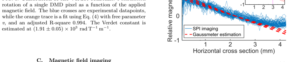
The central claim is that single-pixel polarimetric imaging can be grafted onto a hot-atom Faraday magnetometer to yield magnetic field maps at micrometer scale. The proof uses differential Hadamard patterns ($n=64$) imaged onto a 70 mm $^{87}$Rb cell at $70^\circ$C; the four measured polarization intensities give the rotation angle $\Phi = \frac{1}{2}\arctan\left(\frac{D-A}{H-V}\right)$, and after one-pixel calibration of the Verdet constant $v=(1.91\pm 0.05)\times10^3\ \mathrm{rad\,T^{-1}m^{-1}}$, the reconstructed image is a map of $B_z$ across the cell. The sample image shows the expected linear gradient along the horizontal axis, matching a gaussmeter reference within the $\pm2$ mm sample-position uncertainty, with a tail-off past $x=3.5$ mm attributed to the Verdet constant changing outside the linear bias regime. The authors present this as the first demonstration of magnetic field single-pixel imaging with a compact warm vapor setup.
Load-bearing premise
The measured Faraday rotation at each pixel is treated as a faithful line-integrated map of the local axial magnetic field with a single, spatially uniform Verdet constant that stays linear over the field range of the sample.
Editorial extensions
If this is right
- Hot-atom Faraday magnetometers can produce two-dimensional magnetic field maps with off-the-shelf DMD and photodetector components, removing the need for camera arrays or scanned probe beams.
- The resolution ceiling is technical, not fundamental: better DMD optics and more laser power should push the current $62.5\,\mu\mathrm{m}$ figure well below the demonstrated value.
- Because each image requires $2\times n^2$ differential Hadamard patterns, imaging time grows rapidly with resolution; compressive-sampling variants could cut the pattern count.
- The same single-pixel polarimetric readout is compatible with balanced photodetectors and squeezed light, offering a route to quantum-enhanced magnetic field imaging in a compact package.
Reading between the lines
- One consequence the paper leaves implicit is that the images are line-of-sight projections: the Faraday rotation integrates the field over the full 70 mm cell, so a compact image cannot, by itself, localize a field source along the beam axis; a thin cell or tomographic reconstruction would be needed for depth information.
- A direct testable extension would be to calibrate the Verdet constant pixel-by-pixel rather than once at the center; if $v$ varies across the 4 mm field from thermal gradients, beam nonuniformity, or local field shifts, the reconstructed field map would shift accordingly.
- The observed tail-off past $x = 3.5$ mm could be read as a map of where the linear-response assumption breaks down; characterizing it as a function of the bias field would turn a known artifact into a dynamic-range diagnostic.
Signed reviews
Editorial analysis
A structured set of objections, weighed in public.
Referee Report
Summary. The paper demonstrates a proof-of-principle magnetic field imaging system based on single-pixel imaging (SPI) of Faraday rotation in a hot 87Rb vapor cell. A DMD projects differential Hadamard patterns onto a ~4x4 mm region, and the transmitted light is analyzed with a four-detector polarimeter to reconstruct 64x64 pixel maps of the Faraday rotation. The Verdet constant is calibrated independently against a Helmholtz-coil field measured with a gaussmeter, and the resulting magnetic field image of a set of ten permanent bar magnets is compared with a gaussmeter-based sample calibration. The manuscript claims a spatial resolution of about 62.5 um for magnetic field imaging, limited by the DMD projection optics and laser power, and frames this as the first demonstration of magnetic field SPI with a compact warm-vapor setup.
Significance. If the resolution claim holds, this is a useful contribution: combining single-pixel techniques with hot-vapor Faraday magnetometry offers a route to high-resolution field imaging without camera arrays or scanned beams, with a compact and potentially quantum-enhanced architecture. The paper has notable strengths: the Verdet constant is calibrated with an independent coil/gaussmeter measurement rather than extracted from the final image, the sample field is benchmarked against a separate gaussmeter scan with a motorized stage, and the authors are candid about the nonlinear Verdet regime and the +-2 mm sample-position uncertainty. The central weakness is that the headline resolution of 62.5 um is inferred from an optical USAF target, not from a magnetic structure, and the magnetic sample is too smooth to constrain the magnetic point-spread function. The quantitative comparison to the gaussmeter is also visual and lacks error bars.
major comments (3)
- [Sec. IV.A and Sec. IV.C] The headline claim of approximately 62.5 um spatial resolution for magnetic field imaging is not established by the presented data. The USAF resolution test in Sec. IV.A characterizes only the optical point-spread function of the DMD projection and 4f system. The magnetic-field sample in Sec. IV.C produces a smooth, nearly linear gradient along x with no sharp magnetic features, so the cross-sections in Fig. 4(b) would remain essentially unchanged under any point-spread function whose width is small compared with the gradient length scale. Additionally, the sensor is a 70-degree-C vapor cell with a 600 us illumination time; thermal atomic motion can average the Faraday signal over a scale on the order of 0.1-0.2 mm, and spin-transport effects are not discussed. I request either a direct magnetic resolution test, such as imaging a sharp field step or a small current-carrying structure, or an explicit characterization and model-based upper bound on the magnetic point-spread function.
- [Sec. IV.C, Fig. 4(b)] The quantitative validation of the magnetic field image lacks a stated metric. No error bars or per-pixel uncertainties are given for the reconstructed field map, and the agreement with the gaussmeter reference is assessed visually while allowing the reference curve to shift by +-2 mm in x because the absolute sample-to-probe distance was measured with a ruler. The manuscript should report a quantitative residual or chi-squared measure that propagates the uncertainty in the Verdet fit, the averaging over approximately 220 detections, and the +-2 mm position uncertainty; this is required to substantiate the claim that the SPI measurement agrees with the gaussmeter reference.
- [Eq. (4) and Sec. IV.C] The conversion from Faraday rotation to a local field value assumes a single uniform Verdet constant and a uniform axial field over the full 70 mm optical path. The measured rotation is actually a line integral of B_z times v along the cell, whereas the gaussmeter reference is a point measurement at the cell centre. The manuscript does not quantify how B_z varies along the optical axis for the bar-magnet sample, nor how this variation affects the reconstructed values. Please state explicitly that the displayed values are line-averaged axial fields and estimate the associated systematic error, especially because the reconstructed field changes by roughly a factor related to the strongly varying magnet geometry across the image.
minor comments (6)
- [Sec. II, Eq. (3)] The reconstruction formula is written with the inverse of a difference of Hadamard matrices, but the normalization factor and the precise meaning of the inverse are not defined; please spell out the exact linear inversion used, including how the positive and negative pattern intensities are combined.
- [Sec. IV.A and abstract] The text states a spatial resolution 'between 62.5 um and 70 um' while the abstract and Sec. V state approximately 62.5 um; please make the reported value and its uncertainty consistent throughout.
- [Sec. V] The sentence 'this can be dramatically improved through the use of a magnetic shield ... as demonstrated in Refs. [27-29]' appears to cite squeezed-light magnetometry papers rather than magnetic-shielding demonstrations; please correct the reference or rephrase.
- [Sec. IV.B] The reported Verdet constant uncertainty of +-0.05 x 10^3 rad T^-1 m^-1 appears to be only the statistical fit error; please also give the systematic contribution from the gaussmeter calibration and from the single-point field measurement.
- [Sec. III.B] The statement 'an average of approximately 220 detections for each pattern' should clarify whether the averaging is over multiple repeats of each pattern or over time samples within the 400 us acquisition window, and how the averaging affects the noise floor.
- [Appendix B] The third-order polynomial fit is said to match the scaling predicted by a 3D COMSOL simulation, but the simulation is not described; either provide the model details or present the fit as purely empirical.
Circularity Check
No significant circularity: the Verdet constant is calibrated independently with a gaussmeter, and the final magnetic field image is compared against a separate gaussmeter reference.
full rationale
The derivation chain is self-contained and does not reduce to its own inputs. The SPI image is reconstructed from differential Hadamard patterns via the invertible linear relation in Eq. (3), with no fitted parameters. The Faraday rotation is converted to field via Eq. (4), Φ = B L v, and the Verdet constant v is calibrated in Sec. IV.B using a single-pixel rotation measurement while the applied Helmholtz-coil field is independently measured with a gaussmeter: 'The magnetic field generated by the coils is measured with a gaussmeter (MF100, FLIR Extech), at a single point between the two coils.' The resulting value, v = (1.91 ± 0.05) × 10^3 rad T^-1 m^-1, is a physical material constant and is not tuned to reproduce the magnetic image. The final magnetic field map in Sec. IV.C is then compared with an independent gaussmeter calibration of the sample described in Appendix B, so the predicted field values are not forced by the calibration fit. There is no load-bearing self-citation or imported uniqueness theorem: the cited works on SPI, Faraday rotation, and squeezed-light magnetometry are external prior literature, and none is used to forbid alternative explanations or to define the central measurement. The USAF-target resolution estimate is an optical calibration rather than a magnetic-field measurement, which may raise a question of whether it fully characterizes the magnetic point-spread function, but that is a validity or correctness concern, not a circularity in the derivation. Overall, the paper's 'prediction' is an independent measurement cross-checked against an external field reference, so no circular step is present.
Assumptions & free parameters
free parameters (1)
- Verdet constant v =
(1.91 ± 0.05) × 10^3 rad T^-1 m^-1
assumptions (5)
- domain assumption Faraday rotation is linear: Phi = B L v (Eq. 4)
- standard math Hadamard patterns form an orthogonal basis for image reconstruction (Eqs. 1-3)
- domain assumption The coil field is uniform across the vapor cell, so a single-point gaussmeter reading suffices for Verdet calibration
- domain assumption The sample field is uniform along the y-axis over the 4 mm imaged region
- domain assumption The Verdet constant is spatially uniform across the imaged region and set by the chosen bias field
Cite this review
Pith. "Pith review of Microscopic magnetic field imaging with hot atoms via single-pixel imaging." pith.science (2026). https://pith.science/paper/JK7WSOU3
@misc{pith2026250813869,
  author       = {Pith},
  title        = {Pith review of: Microscopic magnetic field imaging with hot atoms via single-pixel imaging},
  year         = {2026},
  howpublished = {\url{https://pith.science/paper/JK7WSOU3}},
  note         = {Machine review of arXiv:2508.13869}
}
abstract
In recent years, sensors based on hot atomic vapor cells have emerged as a compact and highly sensitive means of measuring magnetic fields. Such sensors have been deployed in the field for the measurement of, e.g. biological systems, representing a promising practical application of quantum technologies. However, it remains challenging to obtain high-resolution magnetic field images from these sensors, and in most cases the spatial resolution of the system is limited by the sensor size. Here, we demonstrate the combination of single-pixel imaging (SPI) techniques with an atom vapor. Faraday magnetometer to achieve microscopic magnetic field imaging. We demonstrate magnetic field imaging with a spatial resolution of $\approx~62.5\mu m$, limited only by the resolution of our DMD projection system and the absence of magnetic shielding in our experimental setup.
Figures


Figures from the paper (2 more)

Reference graph
Works this paper leans on
-
[1]
I. K. Kominis, T. W. Kornack, J. C. Allred, and M. V. Romalis. A subfemtotesla multichannel atomic magne- tometer. Nature, 422(6932):596–599, 2003
work page 2003
-
[2]
H. B. Dang, A. C. Maloof, and M. V. Romalis. Ultrahigh sensitivity magnetic field and magnetization measure- ments with an atomic magnetometer. Applied Physics Letters, 97(15), 2010
work page 2010
-
[3]
M. P. Ledbetter, I. M. Savukov, V. M. Acosta, D. Bud- ker, and M. V. Romalis. Spin-exchange-relaxation-free magnetometry with Cs vapor. Physical Review A , 77(3), 2008
work page 2008
-
[4]
S. Wildermuth, S. Hofferberth, I. Lesanovsky, E. Haller, L. M. Andersson, S. Groth, I. Bar-Joseph, P. Kr¨ uger, and J. Schmiedmayer. Bose-Einstein condensates: mi- croscopic magnetic-field imaging. Nature, 435(7041):440, 2005
work page 2005
-
[5]
V. Shah, S. Knappe, P. D. D. Schwindt, and J. Kitch- ing. Subpicotesla atomic magnetometry with a micro- fabricated vapour cell. Nat. Photonics , 1(11):649–652, 2007
work page 2007
-
[6]
V. Shah and M. V. Romalis. Spin-exchange relaxation- free magnetometry using elliptically polarized light. Phys. Rev. A , 80(1), 2009
work page 2009
-
[7]
W. C. Griffith, S. Knappe, and J. Kitching. Femtotesla atomic magnetometry in a microfabricated vapor cell. Opt. Express, 18(26):27167–27172, 2010
work page 2010
-
[8]
T. Pyragius, H. M. Florez, and T. Fernholz. Voigt-effect- based three-dimensional vector magnetometer. Phys. Rev. A, 100:023416, 2019
work page 2019
Show all 45 references
-
[9]
M. J. Brookes, J. Leggett, M. Rea, R. M. Hill, N. Holmes, El. Boto, and R. Bowtell. Magnetoencephalography with optically pumped magnetometers (opm-meg): the next generation of functional neuroimaging. Trends in Neuro- sciences, 45(8):621–634, 2022
2022
-
[10]
Dawson, Ca
R. Dawson, Ca. O’Dwyer, M. S. Mrozowski, E. Irwin, J. P. McGilligan, D. P. Burt, D. Hunter, S. Ingleby, M. Rea, N. Holmes, M. J. Brookes, P. F. Griffin, and E. Riis. Portable single-beam cesium zero-field magne- tometer for magnetocardiography. J. Optical Microsys- tems, 3(04), 2023
2023
-
[11]
B. U. Westner, J. I. Lubell, M. Jensen, S. Hokland, and S. S. Dalal. Contactless measurements of retinal activ- ity using optically pumped magnetometers. NeuroImage, 243:118528, 2021
2021
-
[12]
E. E. Mikhailov, I. Novikova, M. D. Havey, and F. A. Narducci. Magnetic field imaging with atomic Rb vapor. Opt. Lett., 34(22):3529–3531, 2009
2009
-
[13]
O. Alem, R. Mhaskar, Ricardo J., D. Sheng, J. LeBlanc, L. Trahms, T. Sander, J. Kitching, and S. Knappe. Magnetic field imaging with microfabricated optically- pumped magnetometers. Opt. Express, 25(7):7849–7858, 2017
2017
-
[14]
Hunter, C
D. Hunter, C. Perrella, A. McWilliam, J. P. McGilligan, M. Mrozowski, S. J. Ingleby, P. F. Griffin, D. Burt, A. N. Luiten, and E. Riis. Free-induction-decay magnetic field imaging with a microfabricated Cs vapor cell. Opt. Ex- press, 31(20):33582–33595, 2023
2023
-
[15]
B¨ ohi and P
P. B¨ ohi and P. Treutlein. Simple microwave field imaging technique using hot atomic vapor cells. Appl. Phys. Lett. , 101(18):181107, 2012
2012
-
[16]
Horsley, G
A. Horsley, G. Du, and P. Treutlein. Widefield microwave imaging in alkali vapor cells with sub-100 µm resolution. New J. Phys. , 17(11):112002, 2015
2015
-
[17]
Schlossberger, T
N. Schlossberger, T. McDonald, K. Su, R. Talashila, R. Behary, C. L. Patrick, D. Hammerland, E. E. Mikhailov, S. Aubin, I. Novikova, C. L. Holloway, and N. Prajapati. Two-dimensional imaging of electromag- netic fields via light sheet fluorescence imaging with Ry- dberg atoms, 2024
2024
-
[18]
Affolderbach, G
C. Affolderbach, G. Du, T. Bandi, A. Horsley, P. Treut- lein, and G. Mileti. Imaging microwave and DC magnetic fields in a vapor-cell Rb atomic clock. IEEE Trans. In- strum. Meas., 64(12):3629–3637, 2015
2015
-
[19]
M. F. Duarte, M. A. Davenport, D. Takhar, J. N. Laska, T. Sun, K. F. Kelly, and R. G. Baraniuk. Single-pixel imaging via compressive sampling. IEEE Signal Process- ing Magazine , 25(2):83–91, 2008
2008
-
[20]
P. N. Schatz and A. J. McCaffery. The Faraday effect. Quarterly Reviews, Chemical Society , 23(4):552, 1969
1969
-
[21]
Dur´ an, P
V. Dur´ an, P. Clemente, M. Fern´ andez-Alonso, E. Ta- jahuerce, and J. Lancis. Single-pixel polarimetric imag- ing. Opt. Lett., 37(5):824–826, 2012
2012
-
[22]
S. S. Welsh, M. P Edgar, R. Bowman, B. Sun, and M. J. Padgett. Near video-rate linear stokes imaging with single-pixel detectors. J. Opt. , 17(2):025705, 2015
2015
-
[23]
H. Wu, M. Zhao, F. Li, Z. Tian, and M. Zhao. Underwa- ter polarization-based single pixel imaging. J. Soc. Inf. Disp., 28(2):157–163, 2020
2020
-
[24]
K. L. C. Seow, P. T¨ or¨ ok, and M. R. Foreman. Sin- gle pixel polarimetric imaging through scattering media. Opt. Lett., 45(20):5740–5743, 2020
2020
-
[25]
Y. Chen, K. Yin, D. Shi, W. Yang, J. Huang, Z. Guo, 8 K. Yuan, and Y. Wang. Detection and imaging of dis- tant targets by near-infrared polarization single-pixel li- dar. Appl. Opt. , 61(23):6905–6914, 2022
2022
-
[26]
G. M. Gibson, S. D. Johnson, and M. J. Padgett. Single- pixel imaging 12 years on: a review. Optics Express , 28(19):28190, 2020
2020
-
[27]
Wolfgramm, A
F. Wolfgramm, A. Cer` e, F. A. Beduini, A. Predojevi´ c, M. Koschorreck, and M. W. Mitchell. Squeezed-light optical magnetometry. Physical Review Letters , 105(5), 2010
2010
-
[28]
Horrom, R
T. Horrom, R. Singh, J. P. Dowling, and E. E. Mikhailov. Quantum-enhanced magnetometer with low-frequency squeezing. Physical Review A , 86(2), 2012
2012
-
[29]
L. Bai, X. Wen, Y. Yang, L. Zhang, J. He, Y. Wang, and J. Wang. Quantum-enhanced rubidium atomic mag- netometer based on Faraday rotation via 795 nm Stokes operator squeezed light. Journal of Optics , 23(8):085202, 2021
2021
-
[30]
Zhang, X
Z. Zhang, X. Wang, G. Zheng, and J. Zhong. Hadamard single-pixel imaging versus Fourier single-pixel imaging. Opt. Express, 25(16):19619, 2017
2017
-
[31]
C. P. Pearman, C. S. Adams, S. G. Cox, P. F. Grif- fin, D. A. Smith, and I. G. Hughes. Polarization spec- troscopy of a closed atomic transition: applications to laser frequency locking. J. Phys. B At. Mol. Opt. Phys. , 35(24):5141–5151, 2002
2002
-
[32]
B. Gombala. STMSpeeduino, 2024
2024
-
[33]
E. B. Alexandrov. Recent progress in optically pumped magnetometers. Phys. Scr. , T105(1):27, 2003
2003
-
[34]
T. M. Tierney, N. Holmes, S. Mellor, Jos´ e D. L´ opez, G. Roberts, R. . Hill, E. Boto, J. Leggett, V. Shah, M. J. Brookes, R. Bowtell, and G. R. Barnes. Optically pumped magnetometers: From quantum origins to multi- channel magnetoencephalography. Neuroimage, 199:598– 608, 2019
2019
-
[35]
Zhang, J
Y. Zhang, J. Suo, Y. Wang, and Q. Dai. Doubling the pixel count limitation of single-pixel imaging via sinu- soidal amplitude modulation. Opt. Express , 26(6):6929, 2018
2018
-
[36]
M. Sun, L. Meng, M. P. Edgar, M. J. Padgett, and N. Radwell. A Russian Dolls ordering of the Hadamard basis for compressive single-pixel imaging. Sci. Rep. , 7(1):3464, 2017
2017
-
[37]
Kilcullen, T
P. Kilcullen, T. Ozaki, and J. Liang. Compressed ultrahigh-speed single-pixel imaging by swept aggregate patterns. Nat. Commun. , 13(1):7879, 2022
2022
-
[38]
E. E. Mikhailov and I. Novikova. Low-frequency vacuum squeezing via polarization self-rotation in Rb vapor. Op- tics Letters, 33(11):1213, 2008
2008
-
[39]
X. Wen, Y. Han, J. Liu, J. He, and J. Wang. Polarization squeezing at the audio frequency band for the Rubidium D1 line. Optics Express, 25(17):20737, 2017
2017
-
[40]
Zhang, M
M. Zhang, M. A. Guidry, R. N. Lanning, Z. Xiao, J. P. Dowling, I. Novikova, and E. E. Mikhailov. Multipass configuration for improved squeezed vacuum generation in hot Rb vapor. Physical Review A , 96(1), 2017
2017
-
[41]
J. Zhao, Z. Yu, X. Chen, Y. Wu, X. Liang, W. Huang, K. Zhang, C. Yuan, and L. Q. Chen. Ultra-stable and high-performance squeezed vacuum source enabled via artificial intelligence control. Science Advances, 11(18), 2025
2025
-
[42]
M. A. Taylor, J. Janousek, V. Daria, J. Knittel, B. Hage, H. Bachor, and W. P. Bowen. Biological measurement be- yond the quantum limit. Nature Photonics, 7(3):229–233, 2013
2013
-
[43]
Sabines-Chesterking, A
J. Sabines-Chesterking, A. R. McMillan, P. A. Moreau, S. K. Joshi, S. Knauer, E. Johnston, J. G. Rarity, and J. C. F. Matthews. Twin-beam sub-shot-noise raster- scanning microscope. Optics Express, 27(21):30810, 2019
2019
-
[44]
Atkinson, E.J
G.S. Atkinson, E.J. Allen, G. Ferranti, A.R. McMillan, and J.C.F. Matthews. Quantum enhanced precision esti- mation of transmission with bright squeezed light. Phys- ical Review Applied , 16(4), 2021
2021
-
[45]
B. J. Lawrie and R. C. Pooser. Toward real-time quan- tum imaging with a single pixel camera. Opt. Express , 21(6):7549–7559, 2013
2013
Reviewed August 15, 2026 · model on record in the stance chip above.
Discussion (0). Continue with ORCID to comment.