REVIEW 4 major objections 6 minor 31 references
RadarTrack: Enhancing Ego-Vehicle Speed Estimation with Single-chip mmWave Radar
T0 review · 4 major / 6 minor · reviewed 2026-08-16 · deepseek-v4-flash
Pith's one-line read RadarTrack recovers ego-vehicle speed from mmWave radar phase changes alone, solving a fourth-order kinematic equation and reaching about 2 cm/s median error without any neural network.
desk verdict The quartic phase-based speed estimator is a real idea, but the sub-doppler claim isn't self-contained: the pipeline still depends on Doppler-derived quantities that quantize to zero at the exact speeds the method targets. read the letter →
The pith
A machine-rendered reading of the paper's core claim, the machinery that carries it, and where it could break.
The reading
What carries the argument
The carrying object is the fourth-order kinematic phase equation, $a(t)v_b^4 + b(t,\alpha)v_b^3 + c(t,\alpha)v_b^2 + d(t,\alpha)v_b + e(t) = 0$, derived from the time-dependent range to a static reflector with coefficients $a(t)=t^2$, $b(t,\alpha)=-2K(\alpha)t$, and so on, where $K(\alpha)=Y_0\cos\alpha + X_0\sin\alpha$. It converts chirp-level phase changes into candidate speeds, and the mode of the candidate roots over static points and chirps is the advertised ego-speed. The supporting mechanism is a Doppler radial-velocity classifier that labels static versus dynamic points, plus phase unwrapping that keeps $\Delta\Phi < 2\pi$, bounding the unambiguous speed at about 7.75 m/s.
What would settle it
Mount the radar on a linear stage that moves at a constant 2 cm/s and carries a high-rate encoder as ground truth, with a single static reflector at 45 degrees; if the modal fourth-order root deviates systematically from the encoder speed once pitch oscillation is added, the constant-velocity phase model is disconfirmed.
Extended reading notes
Core claim
The paper's central claim is that the phase trace of static reflectors carries enough information to determine ego-speed exactly: differentiating $r(t)^2 = X(t)^2 + Y(t)^2$ under constant ego-velocity produces a fourth-order equation in $v_b$ whose coefficients involve the measured phase derivative $\Theta(t) = d\Phi/dt$ and the heading offset $\alpha$. Each static point and each chirp yields four candidate roots; since the physical speed is unique, the modal root across a frame is the estimate. Static points are selected by a mode-based threshold on Doppler radial speeds, under the assumption that static reflectors dominate the field of view. The paper reports about 2 cm/s median absolute error on a ground vehicle, up to 4x improvement over Doppler-based estimation, and larger errors on the drone and handheld setups, where the constant-velocity assumption is violated by vibration and rotation.
Load-bearing premise
The load-bearing premise is that the ego-vehicle's velocity magnitude and direction stay constant for the entire 150 ms frame, and that static reflectors outnumber dynamic ones in view; if a platform vibrates, pitches, or sees only moving objects, the kinematic equation and the mode vote lose their foundation.
Editorial extensions
If this is right
- Robots moving slower than the Doppler resolution (here 0.0496 m/s) can still get a continuous speed estimate, because phase tracking is not quantized to Doppler bins.
- Static reflectors no longer need to sit near the radar's boresight; oblique reflectors contribute through the heading angle $\alpha$ estimated from pairwise radial-velocity ratios.
- The approach is real-time on a low-power embedded board, with roughly 0.29 s latency and about 2.25 W power, compared with seconds and higher power for DNN baselines.
- In dynamic scenes, accuracy degrades gracefully with the number of moving reflectors, from 0.018 m/s MAE with three static objects to 0.054 m/s with two dynamic objects, and recovers when a wall enters view.
- The speed estimate is independent of IMU integration, so it avoids drift accumulation at constant and low speeds where accelerometers struggle.
Reading between the lines
- Editorial inference: the fourth-order polynomial models only the scalar speed magnitude; a two-frame or multi-static-point version of the same phase geometry could also estimate the heading direction $\alpha$ over time, turning the method into lightweight odometry rather than just speedometry.
- Editorial inference: the pattern of errors across platforms suggests the method's effective envelope is rigid translation with slow heading change; adding gyroscope-based rotation compensation should recover much of the 0.15-0.16 m/s error seen in handheld and drone runs.
- Editorial inference: because phase-based speed is absolute and drift-free, it could serve as an in-situ calibration signal for IMU bias or as a regularizer for visual-inertial odometry in dark and dusty conditions where cameras fail.
- Editorial inference: a controlled test with sinusoidal speed profiles would separate the constant-velocity assumption from the mode-voting machinery; the model predicts the modal root tracks the mean speed while the root spread grows with acceleration.
Signed reviews
Editorial analysis
A structured set of objections, weighed in public.
Referee Report
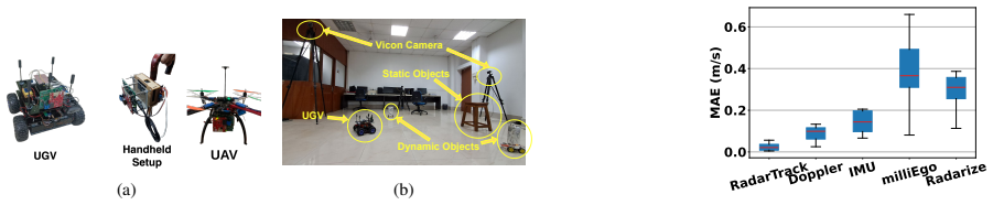
Summary. RadarTrack proposes to estimate ego-vehicle speed from a single-chip mmWave radar using the phase variations of static reflectors. The pipeline first separates static from dynamic radar points using Doppler radial velocities and an estimated angle alpha (Sec. III-C), selects the corresponding range bins, and then, for each static point and chirp, derives a fourth-order polynomial in ego-speed from the kinematics of the range evolution and takes the mode of the polynomial roots across the frame (Sec. III-D). The system is implemented on a TI IWR1843 radar with a Jetson Nano and evaluated on a UGV, a UAV, and a handheld stick against Vicon ground truth, with comparisons to Doppler-only, IMU, MilliEgo, and Radarize baselines, plus resource and latency measurements.
Significance. If the claims hold, RadarTrack would be a valuable lightweight, DNN-free radar-only speed estimator for micro-robots, AR, and other resource-constrained platforms, and its closed-form analytic model is a refreshing alternative to learned odometry. The paper's strengths include a transparent kinematic derivation in Sec. III-D, a real hardware prototype with Vicon ground truth across three platforms, direct comparison against four baselines, and explicit reporting of power, CPU, memory, and latency. The central derivation is almost correct, but the printed Eq. (4) contains a sign error, the sub-Doppler claim currently relies on an unstated source for the angle alpha, and the evaluation narrative contains internally inconsistent error numbers. These issues are addressable, which is why I recommend major revision rather than rejection.
major comments (4)
- [Sec. III-D, Eq. (4)] Eq. (4) prints r_t = sqrt(r_0^2 - 2 v_b t K(alpha) - v_b^2 t^2), but expanding r(t)^2 = (X_0 - v_b cos(alpha) t)^2 + (Y_0 - v_b sin(alpha) t)^2 gives a + v_b^2 t^2 term, not a minus term. The coefficients of Eq. (5) correspond to the corrected plus sign; with the printed minus sign, differentiating Eq. (4) would give different coefficients, including a v^2 coefficient of K^2 + t^2 c^2 Theta^2 instead of the stated K^2 - t^2 c^2 Theta^2. Please correct Eq. (4) and add a sentence showing the consistency check that leads to Eq. (5), since this is the load-bearing derivation of the paper.
- [Sec. III-C and Sec. III-D, Doppler dependence at sub-Doppler speeds] The static/dynamic segmentation in Eq. (1) and the angle alpha in Eq. (2) both use the PCD radial velocities v_ri. With the stated radial-speed resolution of 0.0496 m/s, the paper's headline low-speed demonstration at about 1.5 cm/s (Fig. 8(b)) is below one Doppler bin, so v_ri values are quantized to zero or plus/minus one bin. At v_ri = 0, the ratio in Eq. (2) is undefined and Eq. (1) cannot separate static from dynamic points; at plus/minus one bin, the ratio is noise-dominated. The paper does not state how alpha is initialized or maintained during the 1.5 cm/s trial. If alpha is fixed to a known mounting direction or taken from previous high-speed frames, that is an unstated input; if it is estimated per-frame from Doppler, the sub-Doppler result does not have a reliable alpha. In either case, the abstract's claim of a phase-based method 'solely based on signal processing' is not established for the regime that motivates the paper. Please specify the source of alpha in each experiment and add an ablation that runs the estimator without Doppler-based alpha.
- [Sec. V-A, error summary] The text says that RadarTrack achieves 'approx 5% of the base speed, on average', but the numbers reported in Sec. V-B and Fig. 6 are inconsistent with that claim. The UGV MAE of 0.02 m/s at a 0.25 m/s baseline is 8%, the UAV MAE of 0.15 m/s at a 0.21 m/s baseline is 71%, and the handheld MAE of 0.16 m/s at a 0.35 m/s baseline is 46%. The median MAE of about 2 cm/s in Fig. 6 also does not correspond to a single 'base speed'. Please report relative errors with a clearly defined denominator, or remove the '5%' claim.
- [Sec. III-D, root-mode selection] Eq. (5) is a quartic, so for each static point and chirp it can produce up to four roots, and some roots may be complex or negative. The paper does not state how complex or nonphysical roots are filtered before the mode is taken, nor whether the mode is computed over all N x N_c x 4 roots or only over the real, positive subset. Without this rule, a single spurious repeated root could dominate the mode. Please specify the root-filtering procedure and report the distribution of root multiplicities across a representative frame.
minor comments (6)
- [Sec. III-D, Eq. (4)] The sentence describing the integration is imprecise: Eq. (4) follows by directly expanding r(t)^2 and then taking the square root, not by integrating Eq. (3) from t = 0 to t and from r_0 to r_t. Please rephrase.
- [Sec. III-C, Eq. (1)] The 'mode' is used for continuous quantities in Eqs. (1) and (2) and in the final root mode; please specify the bin width or kernel used to compute the mode in each case.
- [Fig. 8 caption] The caption says that negative speed represents the ego-vehicle approaching a target, but the vertical axis in both panels is labeled with positive velocity values from 0 to 0.4 m/s. Please reconcile the sign convention with the plotted data.
- [Sec. V-E, resource consumption] The statement that RadarTrack 'utilizes only 84% of CPU' is surprising for a method presented as lightweight; please clarify whether this is single-core utilization, how it is measured, and whether the comparison with Radarize and MilliEgo was made on the same hardware with the same measurement period.
- [Sec. V-E, latency] At 10 frames per second the frame time is 100 ms, yet the reported latency is about 0.29 s. Please clarify whether this includes the 150 ms frame accumulation, the processing time, or both, and how the baseline latencies of 3 s and 5 s were measured.
- [Table II] Please report the number of trials, standard deviations, and trajectory lengths for each reflector configuration, since the MAE differences in Table II are small and may not be statistically significant.
Circularity Check
No significant circularity: the quartic phase-derived speed estimate is a kinematic root solve with no ground-truth fit, and prior self-citation is motivational only.
full rationale
RadarTrack's central claim—ego-speed from the fourth-order phase equation—is not circular. Eq. (5) is obtained from the kinematics of r(t) in Eq. (4) and the measured phase derivative Θ(t)=dΦ/dt, with v_b as an algebraic unknown; the root-mode selection is a deterministic post-processing step rather than a regression against Vicon ground truth. The method is evaluated against an external Vicon tracker and compared with several baselines, so the reported accuracy is externally checkable. The only self-citation, [17], is used to motivate extending an earlier single-static-object phase method and is not needed to justify the present derivation. A genuine limitation, though not a circularity, is that static/dynamic segmentation and the angle α in Eqs. (1)-(2) are computed from Doppler radial velocities v_ri, so the "phase-based" claim is narrower than stated; at the 1.5 cm/s sub-Doppler trial in Fig. 8(b), v_ri may be zero or one bin, making α and the static set S underdetermined. The paper also does not specify how X0 and Y0 entering K(α) are obtained. These are input-completeness and correctness concerns, not reductions of the predicted speed to a fitted input. Accordingly, no circular step is identified.
Assumptions & free parameters
free parameters (3)
- k in Eq (1) =
1
- SNR percentile threshold =
95th percentile
- Range-bin association tolerance =
±3 bins
assumptions (6)
- domain assumption Ego-velocity magnitude and direction remain constant during a radar frame (150 ms)
- domain assumption Static points outnumber dynamic points in the radar FoV
- domain assumption Phase unwrapping is valid, so consecutive phase change is less than 2π, giving a 7.75 m/s maximum
- domain assumption The resultant phasor of multiple objects in a range bin is dominated by a single phasor (A1 >> A2)
- domain assumption Static targets' radial speeds follow v_r = v_b cos(theta - alpha)
- standard math FMCW phase-range relation Phi = Phi_0 + 4*pi*r/lambda
Cite this review
Pith. "Pith review of RadarTrack: Enhancing Ego-Vehicle Speed Estimation with Single-chip mmWave Radar." pith.science (2026). https://pith.science/paper/K3P52S32
@misc{pith2026250414495,
  author       = {Pith},
  title        = {Pith review of: RadarTrack: Enhancing Ego-Vehicle Speed Estimation with Single-chip mmWave Radar},
  year         = {2026},
  howpublished = {\url{https://pith.science/paper/K3P52S32}},
  note         = {Machine review of arXiv:2504.14495}
}
read the original abstract
In this work, we introduce RadarTrack, an innovative ego-speed estimation framework utilizing a single-chip millimeter-wave (mmWave) radar to deliver robust speed estimation for mobile platforms. Unlike previous methods that depend on cross-modal learning and computationally intensive Deep Neural Networks (DNNs), RadarTrack utilizes a novel phase-based speed estimation approach. This method effectively overcomes the limitations of conventional ego-speed estimation approaches which rely on doppler measurements and static surrondings. RadarTrack is designed for low-latency operation on embedded platforms, making it suitable for real-time applications where speed and efficiency are critical. Our key contributions include the introduction of a novel phase-based speed estimation technique solely based on signal processing and the implementation of a real-time prototype validated through extensive real-world evaluations. By providing a reliable and lightweight solution for ego-speed estimation, RadarTrack holds significant potential for a wide range of applications, including micro-robotics, augmented reality, and autonomous navigation.
Figures


Figures from the paper (4 more)



Reference graph
Works this paper leans on
-
[17]
Poster: Dynamic ego-velocity estimation using moving mmwave radar: A phase- based approach,
A. Sen, S. Chakraborty, S. Tripathy, and S. Chakraborty, “Poster: Dynamic ego-velocity estimation using moving mmwave radar: A phase- based approach,” in ACM MobiSys Posters, 2024, pp. 692–693
work page 2024
-
[1]
Closing the gaps in inertial motion tracking,
S. Shen, M. Gowda, and R. Roy Choudhury, “Closing the gaps in inertial motion tracking,” in ACM MobiCom, 2018, pp. 429–444
work page 2018
-
[2]
Visual- inertial-wheel odometry with online calibration,
W. Lee, K. Eckenhoff, Y . Yang, P. Geneva, and G. Huang, “Visual- inertial-wheel odometry with online calibration,” in IEEE/RSJ IROS , 2020, pp. 4559–4566
work page 2020
-
[3]
Online imu intrinsic calibration: Is it necessary?
Y . Yang, P. Geneva, X. Zuo, and G. Huang, “Online imu intrinsic calibration: Is it necessary?” 2020 Robotics: Science and Systems , 2020
work page 2020
-
[4]
Vinet: Visual- inertial odometry as a sequence-to-sequence learning problem,
R. Clark, S. Wang, H. Wen, A. Markham, and N. Trigoni, “Vinet: Visual- inertial odometry as a sequence-to-sequence learning problem,” in AAAI, vol. 31, no. 1, 2017
work page 2017
-
[5]
Vins-mono: A robust and versatile monocular visual-inertial state estimator,
T. Qin, P. Li, and S. Shen, “Vins-mono: A robust and versatile monocular visual-inertial state estimator,” IEEE T-RO, vol. 34, no. 4, pp. 1004– 1020, 2018
work page 2018
-
[6]
Soli: Ubiquitous gesture sensing with millimeter wave radar,
J. Lien, N. Gillian, M. E. Karagozler, P. Amihood, C. Schwesig, E. Olson, H. Raja, and I. Poupyrev, “Soli: Ubiquitous gesture sensing with millimeter wave radar,” ACM TOG, vol. 35, no. 4, pp. 1–19, 2016
work page 2016
-
[7]
Autonomous obstacle avoidance for uav based on fusion of radar and monocular camera,
H. Yu, F. Zhang, P. Huang, C. Wang, and L. Yuanhao, “Autonomous obstacle avoidance for uav based on fusion of radar and monocular camera,” in IEEE/RSJ IROS, 2020, pp. 5954–5961
work page 2020
Show all 31 references
-
[8]
Geryon: Edge assisted real-time and robust object detection on drones via mmwave radar and camera fusion,
K. Deng, D. Zhao, Q. Han, S. Wang, Z. Zhang, A. Zhou, and H. Ma, “Geryon: Edge assisted real-time and robust object detection on drones via mmwave radar and camera fusion,” ACM IMWUT, vol. 6, no. 3, pp. 1–27, 2022
2022
-
[9]
Introduction to mmwave sensing: Fmcw radars,
S. Rao, “Introduction to mmwave sensing: Fmcw radars,” Texas Instru- ments (TI) mmWave Training Series , pp. 1–11, 2017
2017
-
[10]
Icp-flow: Lidar scene flow estimation with ICP,
Y . Lin and H. Caesar, “Icp-flow: Lidar scene flow estimation with ICP,” in IEEE/CVF CVPR, 2024, pp. 15 501–15 511
2024
-
[11]
milliego: single-chip mmwave radar aided egomotion estimation via deep sensor fusion,
C. X. Lu, M. R. U. Saputra, P. Zhao, Y . Almalioglu, P. P. De Gusmao, C. Chen, K. Sun, N. Trigoni, and A. Markham, “milliego: single-chip mmwave radar aided egomotion estimation via deep sensor fusion,” in ACM SenSys, 2020, pp. 109–122
2020
-
[12]
Radar-inertial ego-velocity estimation for visually degraded environments,
A. Kramer, C. Stahoviak, A. Santamaria-Navarro, A.-A. Agha- Mohammadi, and C. Heckman, “Radar-inertial ego-velocity estimation for visually degraded environments,” in IEEE ICRA , 2020, pp. 5739– 5746
2020
-
[13]
Milli- rio: Ego-motion estimation with low-cost millimetre-wave radar,
Y . Almalioglu, M. Turan, C. X. Lu, N. Trigoni, and A. Markham, “Milli- rio: Ego-motion estimation with low-cost millimetre-wave radar,” IEEE Sensors Journal, vol. 21, no. 3, pp. 3314–3323, 2020
2020
-
[14]
Less is more: Physical-enhanced radar-inertial odometry,
Q. Huang, Y . Liang, Z. Qiao, S. Shen, and H. Yin, “Less is more: Physical-enhanced radar-inertial odometry,” in IEEE ICRA, 2024
2024
-
[15]
Precise ego-motion estimation with millimeter-wave radar under diverse and challenging conditions,
S. H. Cen and P. Newman, “Precise ego-motion estimation with millimeter-wave radar under diverse and challenging conditions,” in IEEE ICRA, 2018, pp. 6045–6052
2018
-
[16]
Radarize: Enhancing radar slam with generalizable doppler-based odometry,
E. Sie, X. Wu, H. Guo, and D. Vasisht, “Radarize: Enhancing radar slam with generalizable doppler-based odometry,” inACM MobiSys, 2024, pp. 331–344
2024
-
[18]
Deepvo: Towards end-to- end visual odometry with deep recurrent convolutional neural networks,
S. Wang, R. Clark, H. Wen, and N. Trigoni, “Deepvo: Towards end-to- end visual odometry with deep recurrent convolutional neural networks,” in IEEE ICRA, 2017, pp. 2043–2050
2017
-
[19]
Demon: Depth and motion network for learning monocular stereo,
B. Ummenhofer, H. Zhou, J. Uhrig, N. Mayer, E. Ilg, A. Dosovitskiy, and T. Brox, “Demon: Depth and motion network for learning monocular stereo,” in IEEE CVPR, 2017, pp. 5038–5047
2017
-
[20]
Deep virtual stereo odometry: Leveraging deep depth prediction for monocular direct sparse odometry,
N. Yang, R. Wang, J. Stuckler, and D. Cremers, “Deep virtual stereo odometry: Leveraging deep depth prediction for monocular direct sparse odometry,” in ECCV, 2018, pp. 817–833
2018
-
[21]
Ionet: Learning to cure the curse of drift in inertial odometry,
C. Chen, X. Lu, A. Markham, and N. Trigoni, “Ionet: Learning to cure the curse of drift in inertial odometry,” in AAAI, vol. 32, no. 1, 2018
2018
-
[22]
Deep neural network based inertial odometry using low-cost inertial measurement units,
C. Chen, C. X. Lu, J. Wahlström, A. Markham, and N. Trigoni, “Deep neural network based inertial odometry using low-cost inertial measurement units,” IEEE TMC, vol. 20, no. 4, pp. 1351–1364, 2019
2019
-
[23]
Push the limit of single-chip mmwave radar-based egomotion estimation with moving objects in fov,
R. Ding, H. Jin, J. Ding, X. Wang, G. Fan, F. Zhu, X. Tian, and L. Kong, “Push the limit of single-chip mmwave radar-based egomotion estimation with moving objects in fov,” in ACM SenSys, 2023, pp. 417– 430
2023
-
[24]
4d iriom: 4d imaging radar inertial odometry and mapping,
Y . Zhuang, B. Wang, J. Huai, and M. Li, “4d iriom: 4d imaging radar inertial odometry and mapping,” IEEE Robotics and Automation Letters, vol. 8, no. 6, pp. 3246–3253, 2023
2023
-
[25]
See through smoke: robust indoor mapping with low-cost mmwave radar,
C. X. Lu, S. Rosa, P. Zhao, B. Wang, C. Chen, J. A. Stankovic, N. Trigoni, and A. Markham, “See through smoke: robust indoor mapping with low-cost mmwave radar,” in ACM MobiSys , 2020, pp. 14–27
2020
-
[26]
High resolution point clouds from mmwave radar,
A. Prabhakara, T. Jin, A. Das, G. Bhatt, L. Kumari, E. Soltanaghai, J. Bilmes, S. Kumar, and A. Rowe, “High resolution point clouds from mmwave radar,” in IEEE ICRA, 2023, pp. 4135–4142
2023
-
[27]
Continuous multi-user activity tracking via room-scale mmwave sensing,
A. Sen, A. Das, S. Pradhan, and S. Chakraborty, “Continuous multi-user activity tracking via room-scale mmwave sensing,” in 2024 ACM/IEEE IPSN, 2024, pp. 163–175
2024
-
[28]
Batmobility: Towards flying without seeing for autonomous drones,
E. Sie, Z. Liu, and D. Vasisht, “Batmobility: Towards flying without seeing for autonomous drones,” in ACM MobiCom, 2023, pp. 1–16
2023
-
[29]
Iwr1843boost,
“Iwr1843boost,” https://www.ti.com/tool/IWR1843BOOST, Aug. 2019, accessed April 22, 2025
2019
-
[30]
An imu-based traffic and road condition monitoring system,
T. Lei, A. A. Mohamed, and C. Claudel, “An imu-based traffic and road condition monitoring system,” HardwareX, vol. 4, p. e00045, 2018
2018
-
[31]
mmspy: Spying phone calls using mmwave radars,
S. Basak and M. Gowda, “mmspy: Spying phone calls using mmwave radars,” in IEEE SP, 2022, pp. 1211–1228
2022
Reviewed August 16, 2026 · model on record in the stance chip above.
Discussion (0). Continue with ORCID to comment.