Design and Implementation of an Automatic Synchronizing and Protection Relay through Power-Hardware-in-the-Loop (PHIL) Simulation
Pith reviewed 2026-05-25 12:47 UTC · model grok-4.3
The pith
An automatic relay synchronizes a distributed generator to the grid from black-start by controlling voltage and frequency on a lab-scale synchronous generator.
A machine-rendered reading of the paper's core claim, the machinery that carries it, and where it could break.
Core claim
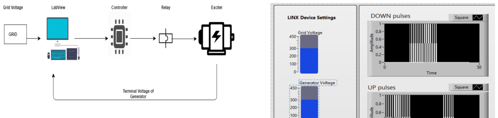
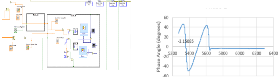
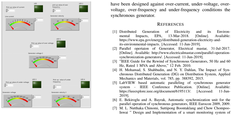
The paper claims that a synchronizing relay built from Arduino data acquisition and LabVIEW software can automatically bring a lab-scale synchronous generator from black-start into synchronism with the utility grid by simultaneously regulating frequency via stepper-motor speed and voltage via excitation control inside a PHIL simulation, while also supplying grid-connected power control and protection, and that the resulting relay satisfies the utility-imposed synchronization requirements.
What carries the argument
The multi-purpose synchronizing relay implemented with Arduino data acquisition and LabVIEW software that performs frequency synchronization via stepper-motor speed control and voltage synchronization via excitation control inside a PHIL simulation.
If this is right
- The relay can perform synchronization from a black-start condition.
- Once connected, the same relay implements active and reactive power control for the generator.
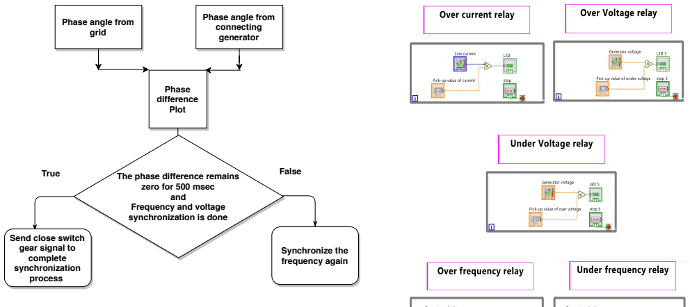
- Protection schemes for the synchronous generator operate in grid-connected mode.
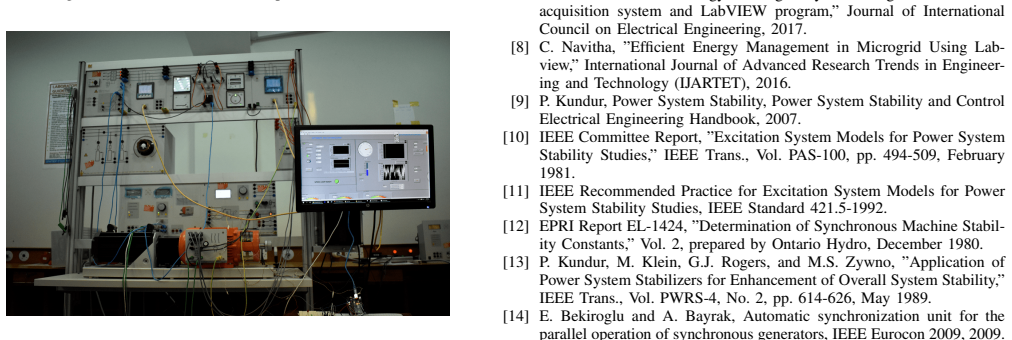
- The complete design was validated on a physical lab-scale test bed.
Where Pith is reading between the lines
- Low-cost microcontroller and software combinations may allow similar relays to be replicated for small distributed resources without custom hardware.
- The PHIL approach could be extended to test synchronization logic against recorded utility disturbance waveforms before field deployment.
- Adding communication interfaces to the relay would enable coordinated synchronization of multiple generators in a microgrid.
Load-bearing premise
The lab-scale test bed and PHIL simulation accurately represent real utility grid conditions and requirements.
What would settle it
A direct connection test on an actual utility feeder in which the relay either fails to achieve voltage and frequency match within the utility limits or trips the protection during the synchronization sequence.
Figures
read the original abstract
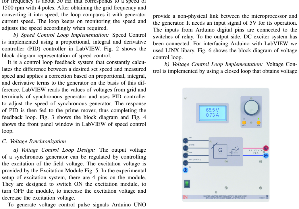
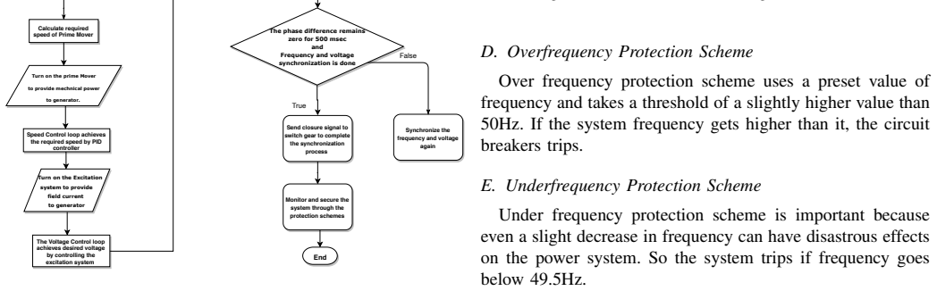
This paper focuses on the design and implementation of an automatic synchronizing and protection relay to automate the synchronization process of a Distributed Energy Resource (DER) to the Main Grid. The proposed design utilize a cost-effective data acquisition using arduino in combination with LabVIEW software to implement the multi-purpose synchronizing relay. The proposed synchronizing relay is capable of synchronizing a Distributed Generator (DG) to the power grid from black-start and fulfills the requirements imposed by the utility. The synchronizing relay is implemented through voltage and frequency control of an actual lab-scale synchronous generator. In the synchronization process, frequency synchronization is done using speed control of the stepper motor as prime mover and voltage synchronization is accomplished using Excitation Control module through Power-Hardware-in-the-Loop (PHIL) simulation. In grid-connected mode, active and reactive power controls and protection schemes for the synchronous generator have also been implemented. The proposed multi-function relay has been deployed and tested on a lab-scale test bed to validate the proposed design and functionality.
Editorial analysis
A structured set of objections, weighed in public.
Referee Report
Summary. The paper describes the design and implementation of a cost-effective automatic synchronizing and protection relay for a distributed generator (DG) using Arduino-based data acquisition combined with LabVIEW. Frequency synchronization is achieved via stepper-motor speed control of the prime mover and voltage synchronization via an excitation control module in a Power-Hardware-in-the-Loop (PHIL) setup on a lab-scale synchronous generator. The work claims that the relay successfully synchronizes the DG from black-start, fulfills utility requirements, and additionally implements active/reactive power control and protection functions in grid-connected mode; the design is stated to have been deployed and tested on a lab-scale test bed.
Significance. If quantitative validation data were supplied, the work would demonstrate a practical, low-cost hardware implementation of a multi-function relay suitable for DER integration. The PHIL-based excitation control provides a realistic test environment that could be of interest for control-hardware validation studies. At present the absence of performance metrics prevents assessment of whether the claimed utility compliance has been achieved.
major comments (2)
- [Abstract] Abstract: the central claim that 'the proposed synchronizing relay ... fulfills the requirements imposed by the utility' is unsupported by any reported measurements of voltage difference, frequency difference, phase-angle difference at breaker closure, synchronization success rate, or direct comparison against IEEE 1547 or utility tolerances.
- [Abstract / validation description] The manuscript states that the relay 'has been deployed and tested on a lab-scale test bed to validate the proposed design and functionality,' yet no tables, figures, or numerical results (e.g., ΔV, Δf, Δθ statistics, protection trip times, or black-start test outcomes) are supplied to substantiate this validation.
minor comments (2)
- Clarify the exact utility standards or numerical tolerances referenced (voltage, frequency, phase-angle windows) so that readers can judge compliance.
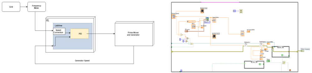
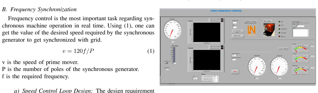
- The description of the PHIL interface and stepper-motor control loop would benefit from a block diagram or timing diagram showing signal flow between Arduino, LabVIEW, and the generator.
Simulated Author's Rebuttal
We thank the referee for the constructive feedback highlighting the need for quantitative validation metrics. We agree that the current manuscript does not include the requested performance data and will revise it accordingly to strengthen the claims.
read point-by-point responses
-
Referee: [Abstract] Abstract: the central claim that 'the proposed synchronizing relay ... fulfills the requirements imposed by the utility' is unsupported by any reported measurements of voltage difference, frequency difference, phase-angle difference at breaker closure, synchronization success rate, or direct comparison against IEEE 1547 or utility tolerances.
Authors: We acknowledge that the abstract's claim regarding utility compliance lacks supporting quantitative evidence in the submitted version. In the revised manuscript, we will add specific measured values for ΔV, Δf, and Δθ at the moment of breaker closure, synchronization success rates from multiple trials, and direct comparisons against IEEE 1547 tolerances and typical utility requirements. These will be drawn from the existing experimental records of the PHIL-based tests. revision: yes
-
Referee: [Abstract / validation description] The manuscript states that the relay 'has been deployed and tested on a lab-scale test bed to validate the proposed design and functionality,' yet no tables, figures, or numerical results (e.g., ΔV, Δf, Δθ statistics, protection trip times, or black-start test outcomes) are supplied to substantiate this validation.
Authors: We agree that the validation description is not supported by numerical results or figures in the current manuscript. The revised version will include new tables and figures presenting ΔV, Δf, Δθ statistics, protection trip times, and black-start synchronization outcomes from the lab-scale PHIL experiments to substantiate the deployment and testing claims. revision: yes
Circularity Check
No circularity: hardware implementation paper without derivations or self-referential predictions
full rationale
The paper is a descriptive account of designing and testing a synchronizing relay on a lab-scale synchronous generator using Arduino/LabVIEW and PHIL simulation. No equations, parameter fitting, predictions, or derivation chains appear in the provided text. The central claim rests on the physical implementation and qualitative validation on the test bed rather than any reduction of outputs to inputs by construction. Self-citations, if present, are not load-bearing for any mathematical result. This is a standard non-circular engineering implementation report.
Axiom & Free-Parameter Ledger
Reference graph
Works this paper leans on
- [1]
- [2]
-
[3]
”IEEE Guide for the Rewind of Synchronous Generators, 50 Hz and 60 Hz, Rated 1 MV A and Above,” 12 Feb. 2010
work page 2010
-
[4]
H. Mohamad, S. Shahbudin, and N. Y . Dahlan, The Impact of Syn- chronous Distributed Generation (DG) on Distribution System, Applied Mechanics and Materials, vol. 785, pp. 388392, 2015
work page 2015
- [5]
-
[7]
M. L. Nutthaka Chinomi, Suttipong Boontaklang and Chow Chompoo- Inwai ” Design and Implementation of a smart monitoring system of a modern renewable energy micro-grid system using a low-cost data acquisition system and LabVIEW program,” Journal of International Council on Electrical Engineering, 2017
work page 2017
-
[8]
C. Navitha, ”Efficient Energy Management in Microgrid Using Lab- view,” International Journal of Advanced Research Trends in Engineer- ing and Technology (IJARTET), 2016
work page 2016
-
[9]
P. Kundur, Power System Stability, Power System Stability and Control Electrical Engineering Handbook, 2007
work page 2007
-
[10]
IEEE Committee Report, ”Excitation System Models for Power System Stability Studies,” IEEE Trans., V ol. PAS-100, pp. 494-509, February 1981
work page 1981
-
[11]
IEEE Recommended Practice for Excitation System Models for Power System Stability Studies, IEEE Standard 421.5-1992
work page 1992
-
[12]
2, prepared by Ontario Hydro, December 1980
EPRI Report EL-1424, ”Determination of Synchronous Machine Stabil- ity Constants,” V ol. 2, prepared by Ontario Hydro, December 1980
work page 1980
- [13]
-
[14]
E. Bekiroglu and A. Bayrak, Automatic synchronization unit for the parallel operation of synchronous generators, IEEE Eurocon 2009, 2009
work page 2009
-
[15]
1, 2 and 3, prepared by General Electric Company, 1984
EPRI Report EL-3359, ”Improvement in Accuracy of Prediction of Elec- trical Constants, and Generator Model for Subsynchronous Resonance Conditions,” Final Report of EPRI Projects RP 1288-1 and RP, V ols. 1, 2 and 3, prepared by General Electric Company, 1984
work page 1984
-
[16]
P.M. Anderson and A.A Fouad, Power System Control and Stability, Iowa State University Press, Ames, Iowa, 1977
work page 1977
-
[17]
Paithankar, Yeshwant G., and S. R. Bhide. Fundamentals of power system protection. PHI Learning Pvt. Ltd., 2011
work page 2011
-
[18]
C. J. Mozina, Coordination of generator protection with generator exci- tation control and generator capability, 2009 62nd Annual Conference for Protective Relay Engineers, 2009
work page 2009
-
[19]
E. Pajuelo, R. Gokaraju, and M. S. Sachdev, Coordination of overexci- tation limiter, field overcurrent protection and generator control, IEEE PES General Meeting, 2010
work page 2010
discussion (0)
Sign in with ORCID, Apple, or X to comment. Anyone can read and Pith papers without signing in.