Simulation Study of Coupling Effects Between a Hall Thruster and a Power Processing Unit
Pith reviewed 2026-06-30 08:58 UTC · model grok-4.3
The pith
Co-simulation of Hall thruster and power unit produces sustained 11 kHz current oscillation
A machine-rendered reading of the paper's core claim, the machinery that carries it, and where it could break.
Core claim
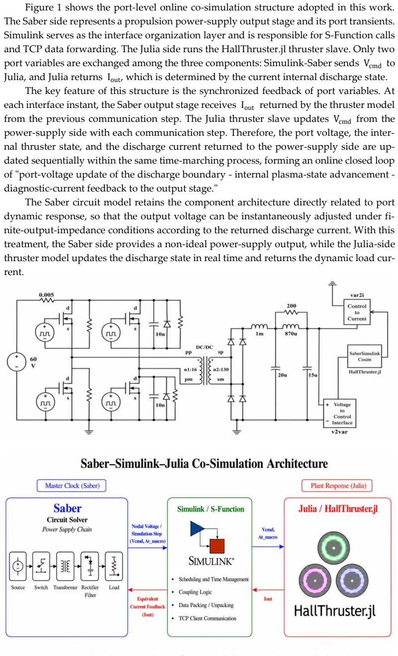
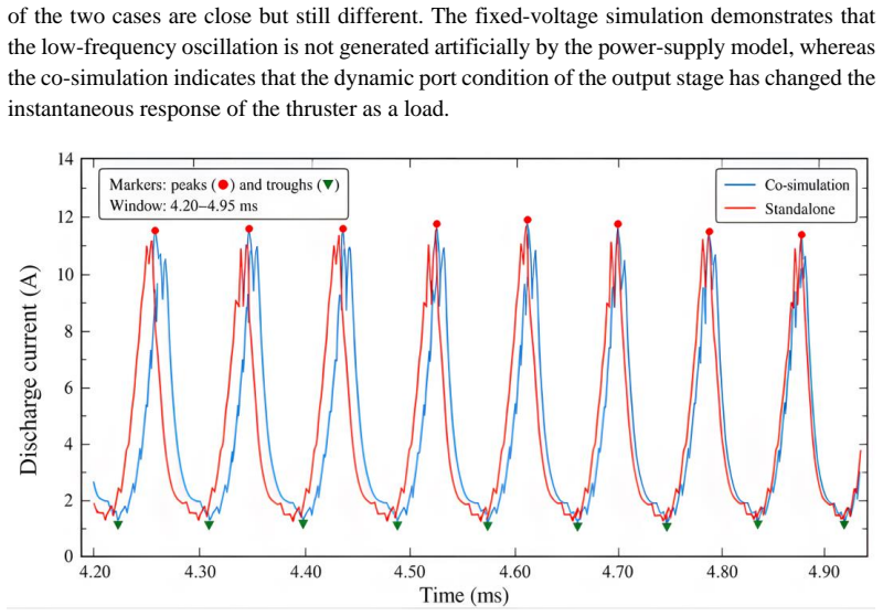
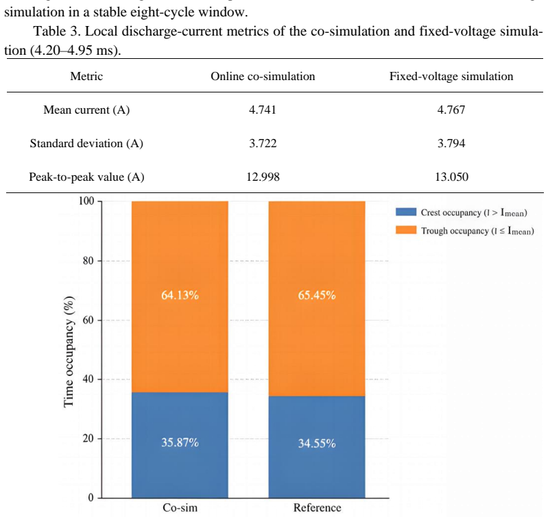
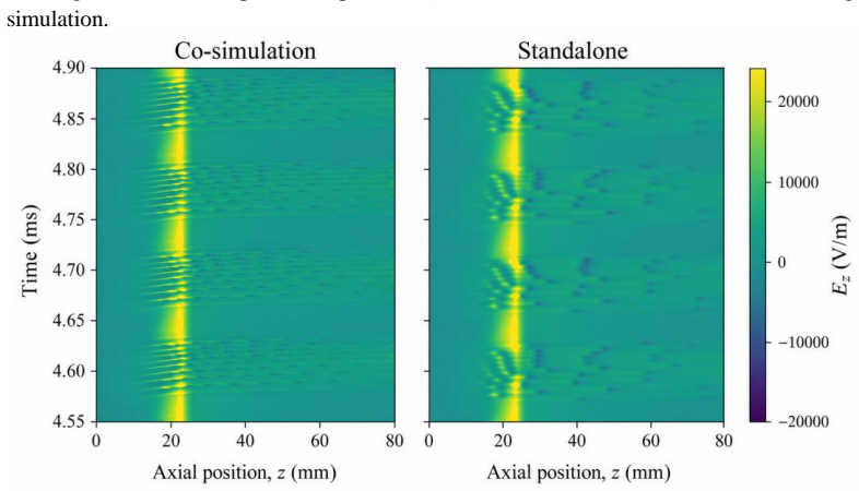
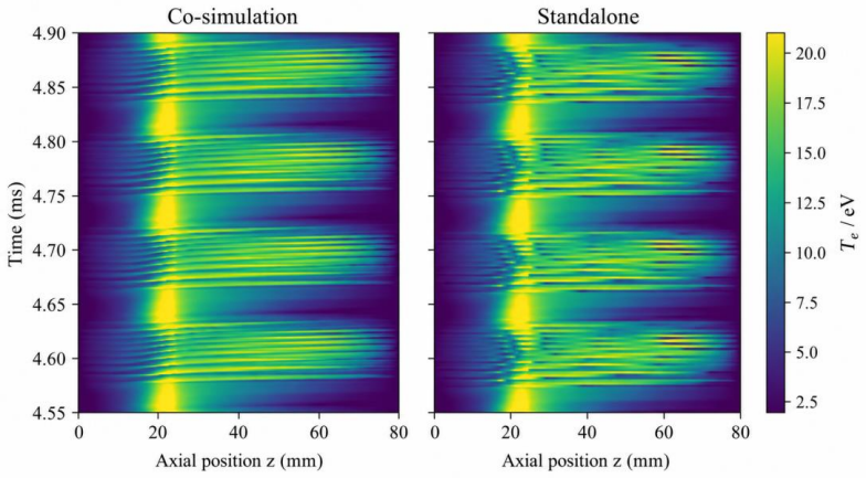
Encapsulating the one-dimensional discharge model as an externally callable slave enables synchronized closed-loop exchange between power-port voltage Vcmd and thruster discharge current Iout. This produces a sustained low-frequency response at approximately 11 kHz and observable differences in port waveforms, spectral characteristics, and internal field distributions compared with fixed-voltage standalone simulation.
What carries the argument
HallThruster.jl-Saber-Simulink co-simulation treating the thruster discharge model as an externally callable slave for closed-loop voltage-current interaction
If this is right
- The discharge current under co-simulation exhibits a sustained low-frequency response at approximately 11 kHz.
- Port waveforms and spectral characteristics differ from those in fixed-voltage standalone runs.
- Internal field distributions inside the thruster change when the power unit responds dynamically.
- The method supplies a basis for realistic load analysis of propulsion power supplies and component stress evaluation.
Where Pith is reading between the lines
- Power supply topologies could be tested for stability against this feedback-induced oscillation before hardware construction.
- The 11 kHz mode may arise from interaction between plasma dynamics and supply control loops rather than from the thruster alone.
- Adding multi-dimensional thruster models to the same co-simulation framework could expose additional coupling frequencies.
Load-bearing premise
The one-dimensional discharge model accurately represents the nonlinear real-time load behavior of the physical Hall thruster when voltage and current vary together.
What would settle it
A spectrum measurement of discharge current from a real Hall thruster connected to its power processing unit that shows or lacks a clear peak near 11 kHz.
Figures
read the original abstract
The complex and nonlinear load characteristics of Hall thrusters remain a key challenge in the design of propulsion power-supply output stages. In existing power-supply simu-lations for electric propulsion systems, the Hall thruster is often simplified as a fixed im-pedance or a prescribed current source, which makes it difficult to capture the real-time interaction between the power-supply output stage and the thruster discharge process. To address this issue, this study encapsulates a one-dimensional discharge model as an externally callable thruster slave and proposes a HallThruster.jl-Saber-Simulink co-simu-lation method. The proposed method enables synchronized closed-loop exchange be-tween the power-port voltage Vcmd and the thruster discharge current Iout . The results show that the discharge current under the co-simulation condition exhibits a sustained low-frequency response at approximately 11 kHz. Compared with a fixed-voltage standalone simulation, the co-simulation shows observable differences in port waveforms, spectral characteristics, and internal field distributions. This method provides a co-simu-lation basis for realistic load analysis of propulsion power supplies and subsequent stress evaluation of key components.
Editorial analysis
A structured set of objections, weighed in public.
Referee Report
Summary. The manuscript presents a co-simulation framework that encapsulates a one-dimensional Hall thruster discharge model (HallThruster.jl) as an externally callable slave for synchronized closed-loop exchange of power-port voltage Vcmd and discharge current Iout with a PPU model in Saber-Simulink. It reports that the co-simulation produces a sustained low-frequency oscillation at approximately 11 kHz in the discharge current, together with observable differences in port waveforms, spectral content, and internal field distributions relative to fixed-voltage standalone runs.
Significance. If the 1D model is shown to faithfully reproduce the nonlinear, real-time load dynamics of a physical Hall thruster under variable-voltage drive, the method would supply a practical tool for coupled PPU-thruster analysis and component stress evaluation in electric propulsion systems. The work correctly identifies the limitation of fixed-impedance or current-source approximations in existing PPU simulations.
major comments (2)
- [Abstract] Abstract: The headline claim of a sustained ~11 kHz response and coupling-induced differences rests entirely on internal simulation-to-simulation comparisons; no quantitative validation of the encapsulated 1D discharge model against experimental discharge-current waveforms, breathing-mode frequencies, or higher-fidelity (2-D/3-D) codes is provided, so the observed feature could be an artifact of the 1-D closure or the co-simulation interface.
- [Results] Results section (implied by abstract description): No error bars, convergence checks, or analysis of numerical stability and interface artifacts are reported for the closed-loop Vcmd–Iout exchange, which directly undermines the assertion that the co-simulation produces physically meaningful differences in waveforms and internal fields.
minor comments (1)
- [Abstract] Abstract contains line-break artifacts ('simu-lations', 'im-pedance') that should be corrected in the final version.
Simulated Author's Rebuttal
We thank the referee for the constructive comments. We address each major point below, clarifying the scope of the work as a demonstration of the co-simulation framework.
read point-by-point responses
-
Referee: [Abstract] Abstract: The headline claim of a sustained ~11 kHz response and coupling-induced differences rests entirely on internal simulation-to-simulation comparisons; no quantitative validation of the encapsulated 1D discharge model against experimental discharge-current waveforms, breathing-mode frequencies, or higher-fidelity (2-D/3-D) codes is provided, so the observed feature could be an artifact of the 1-D closure or the co-simulation interface.
Authors: We agree that the study does not include new quantitative validation of the 1D model (HallThruster.jl) against experiments or higher-fidelity codes; that validation is assumed from prior literature on the model. The manuscript's contribution is the closed-loop co-simulation framework and the demonstration that coupling produces differences relative to fixed-voltage runs. We will revise the abstract and conclusions to explicitly state that the 11 kHz feature and waveform differences are obtained within this 1D modeling framework and to note the model-dependent nature of the results. revision: partial
-
Referee: [Results] Results section (implied by abstract description): No error bars, convergence checks, or analysis of numerical stability and interface artifacts are reported for the closed-loop Vcmd–Iout exchange, which directly undermines the assertion that the co-simulation produces physically meaningful differences in waveforms and internal fields.
Authors: We will add a dedicated subsection on numerical implementation in the revised manuscript. This will include description of the synchronization protocol for the Vcmd–Iout interface, time-step selection criteria, and results of convergence tests with respect to simulation parameters and interface tolerances to demonstrate that the reported differences are robust. revision: yes
Circularity Check
No circularity: simulation outputs from encapsulated 1D model
full rationale
The manuscript describes a co-simulation architecture in which a pre-existing one-dimensional discharge model is wrapped as an externally callable slave and driven by time-varying voltage from the PPU simulator. The reported 11 kHz response and waveform differences are direct numerical outputs of that coupled integration; no parameter is fitted to the target result, no equation is defined in terms of its own output, and no self-citation chain is invoked to justify a uniqueness or closure assumption. The derivation chain therefore terminates at the numerical solution of the supplied model equations rather than looping back to its own inputs.
Axiom & Free-Parameter Ledger
axioms (1)
- domain assumption The one-dimensional discharge model sufficiently captures the nonlinear load dynamics of the Hall thruster for the purpose of closed-loop power-supply interaction studies.
Reference graph
Works this paper leans on
-
[1]
On -orbit mission over- view of the low power Hall thruster propulsion system aboard Venμs satellite,
D. Katz Franco, B. Shoor, A. Davidson, R. Zimmerman, L. Appel, V. Rinski, D. Lev, and J. Herscovitz, “On -orbit mission over- view of the low power Hall thruster propulsion system aboard Venμs satellite,” Journal of Electric Propulsion, vol. 3, Art. n o. 15, 2024
2024
-
[2]
2023 Small Satellite Propulsion Technologies Survey,
The Aerospace Corporation, “2023 Small Satellite Propulsion Technologies Survey,” Tech. Rep., 2023
2023
-
[3]
D. M. Goebel and I. Katz, Fundamentals of Electric Propulsion: Ion and Hall Thrusters. Hoboken, NJ, USA: Wiley, 2008
2008
-
[4]
Power processing and control unit of the electric propulsion system,
O. Petrenko, O. Alekseenko, and V. Tolmachov, “Power processing and control unit of the electric propulsion system,” Journal of Rocket-Space Technology, vol. 32, no. 4, pp. 15–22, 2023
2023
-
[5]
A novel power processing unit (PPU) system architecture based on HFAC bus for electric propulsion spacecraft,
M. Fang, D. Zhang, and X. Qi, “A novel power processing unit (PPU) system architecture based on HFAC bus for electric propulsion spacecraft,” IEEE Journal of Emerging and Selected Topics in Power Electronics, vol. 10, no. 5, pp. 5381–5391, 2022
2022
-
[6]
Sub-kW class Hall-effect thruster power processing unit for wide output range applications,
C. R. Rhodes, G. F. Benavides, and L. R. Piñero, “Sub-kW class Hall-effect thruster power processing unit for wide output range applications,” in Proc. 38th International Electric Propulsion Conference, Toulouse, France, 2024, IEPC-2024-331
2024
-
[7]
Plasma oscillations in Hall thrusters,
E. Y. Choueiri, “Plasma oscillations in Hall thrusters,” Physics of Plasmas, vol. 8, no. 4, pp. 1411–1426, 2001
2001
-
[8]
Low frequency oscillations in a stationary plasma thruster,
J.-P. Boeuf and L. Garrigues, “Low frequency oscillations in a stationary plasma thruster,” Journal of Applied Physics, vol. 84, no. 7, pp. 3541–3554, 1998
1998
-
[9]
The origin of the breathing mode in Hall thrusters and its stabilization,
T. Lafleur, P. Chabert, and A. Bourdon, “The origin of the breathing mode in Hall thrusters and its stabilization,” Journal o f Applied Physics, vol. 130, no. 5, Art. no. 053305, 2021
2021
-
[10]
Experimental characterization of Hall thruster breathing mode dynamics,
E. T. Dale and B. A. Jorns, “Experimental characterization of Hall thruster breathing mode dynamics,” Journal of Applied Phys- ics, vol. 130, no. 13, Art. no. 133302, 2021
2021
-
[11]
On the mechanism of ionization oscillations in Hall thrusters,
O. Chapurin, A. Smolyakov, G. J. M. Hagelaar, and Y. Raitses, “On the mechanism of ionization oscillations in Hall thrusters,” Journal of Applied Physics, vol. 129, no. 23, Art. no. 233307, 2021
2021
-
[12]
Fluid and hybrid simulati ons of the ionization instabilities in Hall thrusters,
O. Chapurin, A. Smolyakov, G. J. M. Hagelaar, J. -P. Boeuf, and Y. Raitses, “Fluid and hybrid simulati ons of the ionization instabilities in Hall thrusters,” Journal of Applied Physics, vol. 132, no. 5, Art. no. 053301, 2022
2022
-
[13]
Study of the breathing mode development in Hall thrusters using hybrid simulations,
F. Petronio, A. Alvarez Laguna, A. Bourdon, and P. Chabert, “Study of the breathing mode development in Hall thrusters using hybrid simulations,” Journal of Applied Physics, vol. 135, no. 7, Art. no. 073301, 2024
2024
-
[14]
On the onset of breathing mode in Hall thrusters and the role of electron mobility fluctuations,
L. Leporini, V. Giannetti, M. M. Saravia, F. Califano, S. Camarri, and T. Andreussi, “On the onset of breathing mode in Hall thrusters and the role of electron mobility fluctuations,” Frontiers in Physics, vol. 10, Art. no. 951960, 2022
2022
-
[15]
An unstable 0D model of ionization osci l- lations in Hall thrusters,
L. Leporini, V. Giannetti, M. M. Saravia, F. Califano, S. Camarri, and T. Andreussi, “An unstable 0D model of ionization osci l- lations in Hall thrusters,” Frontiers in Physics, vol. 10, Art. no. 1097813, 2023
2023
-
[16]
Temporally resolved relative kryp ton neutral density during breathing mode of a Hall effect thruster recorded by TALIF,
J. A. Gottfried, S. Antozzi, J. Stienike, S. J. Thompson, J. D. Williams, and A. P. Yalin, “Temporally resolved relative kryp ton neutral density during breathing mode of a Hall effect thruster recorded by TALIF,” Journal of Electric Propul sion, vol. 3, Art. no. 9, 2024
2024
-
[17]
Influence of a power supply model on simulated Hall thruster discharge voltage oscillations,
L. Brieda, J. Koo, and M. Scharfe, “Influence of a power supply model on simulated Hall thruster discharge voltage oscillations,” AIP Advances, vol. 9, no. 2, Art. no. 025320, 2019
2019
-
[18]
Studies of a modulated Hall thruster,
J. Simmonds, Y. Raitses, A. Smolyakov, and O. Chapurin, “Studies of a modulated Hall thruster,” Plasma Sources Science and Technology, vol. 30, no. 5, Art. no. 055011, 2021
2021
-
[19]
Hall effect thruster impedance characterization in ground -based vacuum test facilities,
D. R. Jovel, J. D. Cabrera, and M. L. R. Walker, “Hall effect thruster impedance characterization in ground -based vacuum test facilities,” Journal of Electric Propulsion, vol. 3, Art. no. 31, 2024
2024
-
[20]
Mode transitions in a magnetically shielded Hall thruster. I. Experimentally informed model,
B. A. Jorns, E. Dale, and R. R. Hofer, “Mode transitions in a magnetically shielded Hall thruster. I. Experimentally informed model,” Journal of Applied Physics, vol. 136, no. 5, Art. no. 053301, 2024
2024
-
[21]
HallThruster.jl: a Julia package for 1D Hall thruster discharge simulation,
T. Marks, P. Schedler, and B. Jorns, “HallThruster.jl: a Julia package for 1D Hall thruster discharge simulation,” Journal of Open Source Software, vol. 8, no. 86, Art. no. 4672, 2023
2023
-
[22]
Simulink,
The MathWorks, Inc., “Simulink,” version 8.6 (R2015b), Natick, MA, USA, 2015
2015
-
[23]
Synopsys Saber,
Synopsys, Inc., “Synopsys Saber,” version 2016, Mountain View, CA, USA, 2016. Disclaimer/Publisher’s Note: The statements, opinions and data contained in all publications are solely those of the individual au- thor(s) and contributor(s) and not of MDPI and/or the editor(s). MDPI and/or the editor(s) disclaim responsibility for any injury to people or prop...
2016
discussion (0)
Sign in with ORCID, Apple, or X to comment. Anyone can read and Pith papers without signing in.