REVIEW 4 major objections 5 minor 24 references
Circuit-Based Modeling Approach for Channel Estimation in RIS-Assisted Communications
T0 review · 4 major / 5 minor · reviewed 2026-08-07 · deepseek-v4-flash
Pith's one-line read A circuit-based RIS phase shift matrix, derived from a parallel resonant impedance model, degrades channel estimation relative to the ideal DFT design, but the gap narrows as training duration grows.
desk verdict A plausible incremental study whose main 'training time mitigates circuit loss' claim is likely noise averaging from a circulant S design, not a property of the circuit model. read the letter →
The pith
A machine-rendered reading of the paper's core claim, the machinery that carries it, and where it could break.
The reading
What carries the argument
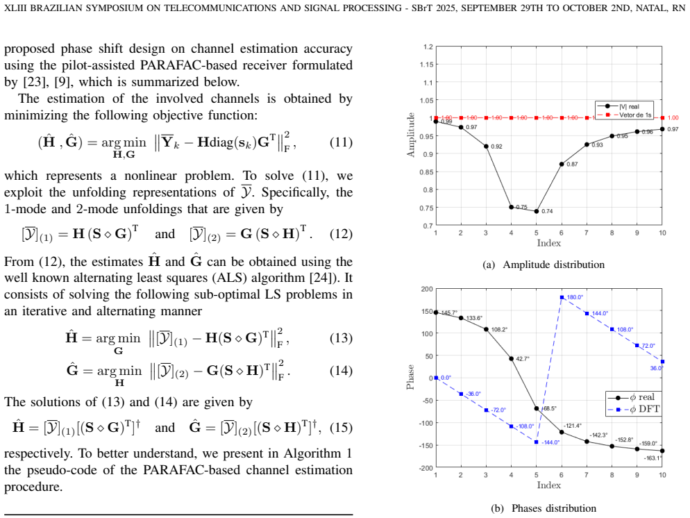
The load-bearing object is the impedance matrix of Eq. (8), whose $(k,n)$-th entry follows the parallel resonant circuit model $Z_{kn}(C,R)=\frac{j\omega L_1\left(j\omega L_2+\frac{1}{j\omega C_{kn}}+R_{kn}\right)}{j\omega L_1+\left(j\omega L_2+\frac{1}{j\omega C_{kn}}+R_{kn}\right)}$. The reflection coefficient $v_{kn}=\frac{Z_{kn}-Z_0}{Z_{kn}+Z_0}$ maps impedance to a complex amplitude-phase pair, and the proposed phase shift matrix $\mathbf{S}\in\mathbb{C}^{K\times N}$ collects these responses over $K$ circular shifts of the resistance and capacitance vectors. The received signal is modeled as the third-order PARAFAC tensor $\mathcal{Y}=\mathcal{I}_{3,N}\times_1\mathbf{H}\times_2\mathbf{G}\times_3\mathbf{S}$, and alternating least squares on the 1-mode and 2-mode unfoldings recovers $\mathbf{H}$ and $\mathbf{G}$. The coupling of amplitude and phase in $\mathbf{S}$, absent in DFT designs, is what degrades estimation and what additional training blocks compensate for.
What would settle it
Measure the complex reflection coefficient of a fabricated varactor-based RIS element across the stated capacitance and resistance ranges at 2.4 GHz, and compare the measured amplitude and phase to the predictions of Eqs. (5)--(6) using $L_1=2.5$ nH, $L_2=0.7$ nH, $Z_0=377\,\Omega$. Significant deviations would invalidate the proposed phase shift matrix and the simulated NMSE curves.
Extended reading notes
Core claim
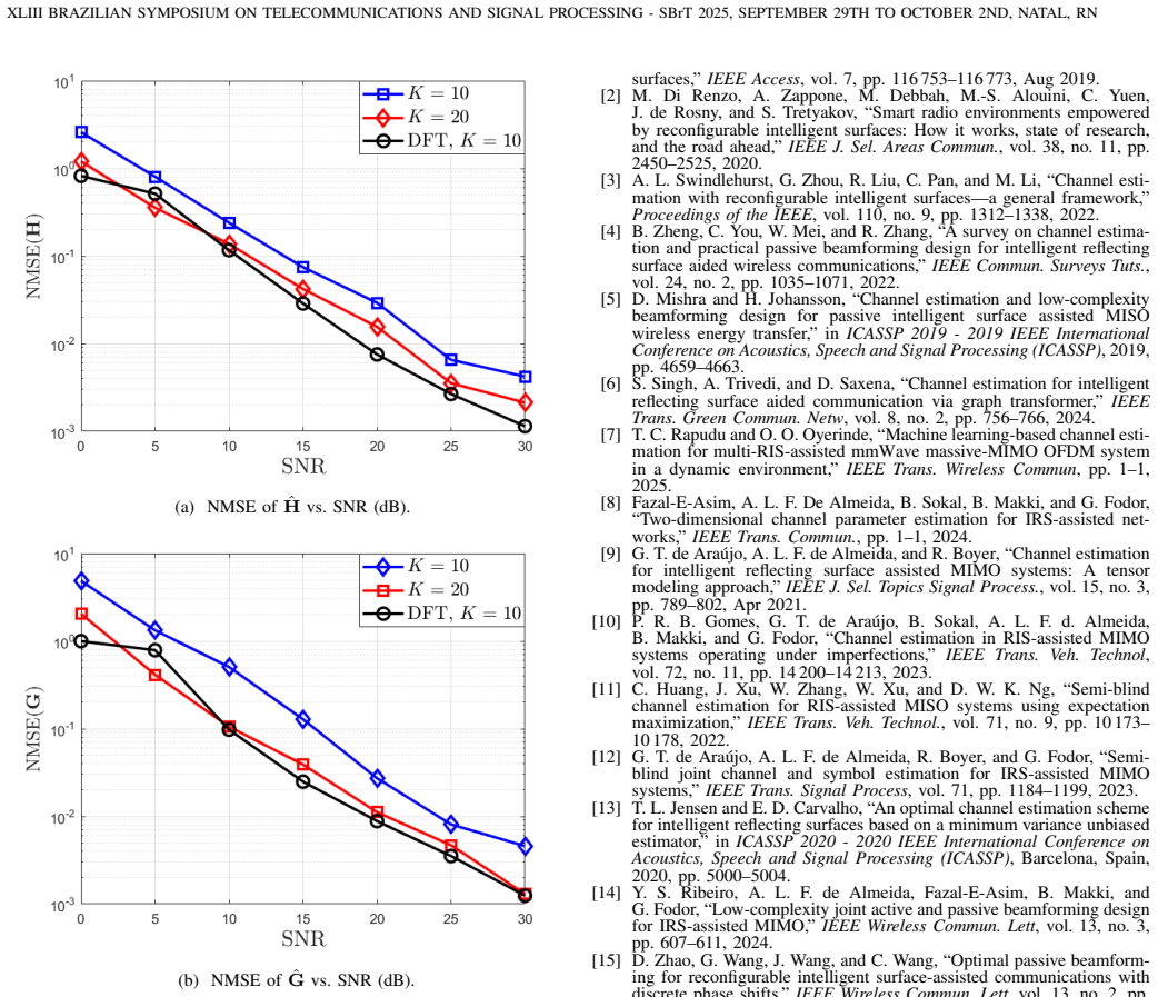
The paper's central claim is that a phase shift matrix built from the parallel-resonant impedance model of Eq. (5) and the reflection coefficient of Eq. (6) is a workable, though suboptimal, design for tensor-based channel estimation. In the proposed design, each entry $S_{kn}$ is the complex reflection coefficient $v_{kn}$ computed from a capacitance $C_{kn}$ and resistance $R_{kn}$, so amplitude and phase are coupled and the matrix departs from the idealized DFT design. Simulations with $M_t=M_r=N=T=10$ and $K\in\{10,20\}$ show an NMSE increase for both estimated channels $\hat{H}$ and $\hat{G}$ relative to the DFT baseline, but the gap shrinks when $K$ grows from 10 to 20. The authors conclude that increasing training duration mitigates the loss, making the circuit-based design viable when enough training blocks are allocated.
Load-bearing premise
If the parallel resonant circuit impedance of Eq. (5) and the reflection coefficient of Eq. (6) do not match the real behavior of a varactor-based RIS element, then the generated phase shift matrix $\mathbf{S}$ will not describe the hardware, and the reported performance loss and its compensation by longer training would not carry over to practice.
Editorial extensions
If this is right
- Any downstream phase-shift design or receiver that assumes an ideal DFT matrix will need to account for the amplitude-phase coupling present in this circuit-based model.
- Allocating more training blocks (larger $K$) is a concrete way to bring circuit-based channel estimation accuracy close to the DFT baseline, at the cost of longer training overhead.
- The proposed phase shift matrix fits the same rank-$N$ PARAFAC structure, so the identifiability and uniqueness conditions for the tensor-based estimator remain applicable.
- The operating region for $R_n$ and $C_n$, chosen to avoid strong attenuation while keeping phase range wide, is itself a tunable system parameter that affects the estimation-quality versus dissipation trade-off.
Reading between the lines
- If measured hardware later confirms Eqs. (5)--(6), the same circuit-derived $\mathbf{S}$ construction could be applied to semi-blind receivers or joint beamforming optimization, where the training-loss trade-off may behave differently.
- The heatmap-based region selection could be replaced by an explicit optimization of the $R$ and $C$ ranges, potentially yielding phase shift matrices that reduce the gap to DFT without extra training.
- For larger arrays the circular-shift construction may not supply enough phase diversity; randomized or optimized resistance and capacitance assignments would be a natural extension to test.
- The finding that training time compensates for hardware non-idealities suggests an adaptive training protocol: measure the operating region first, then choose $K$ accordingly.
Editorial analysis
A structured set of objections, weighed in public.
Referee Report
Summary. This paper studies channel estimation in RIS-assisted MIMO when the RIS phase-shift matrix is generated from a physical resonant-circuit model rather than from the idealized DFT design. Each RIS element's impedance and reflection coefficient are computed via Eqs. (5)-(6), and the paper constructs the training phase-shift matrix S by uniformly sampling resistance and capacitance values and applying circular shifts (Eq. (7)). The resulting S is used with the PARAFAC/ALS channel estimator of [9]. Simulations with Mt=Mr=N=T=10 and K=10,20 report NMSE versus SNR, comparing the circuit-based design with the DFT design. The main empirical claim is that the circuit-based design degrades estimation accuracy relative to the DFT design, but that the degradation is reduced when the training duration K is increased.
Significance. If the claimed effect is real, the paper would provide a useful practical message: circuit-constrained RIS phase patterns can still be used with tensor-based channel estimation, provided the training phase is long enough. The paper is also valuable for making the construction of S from physical component values explicit and for reusing a well-established estimator, which keeps the comparison transparent. The central qualitative finding is plausible and the simulations are consistent with the stated equations. However, the support is not yet complete: the construction of S needs a correctness check, the identifiability/conditioning of the proposed S is not examined, and the K=10 versus K=20 comparison is confounded because the same N=10 patterns are repeated. These issues affect the load-bearing interpretation of Fig. 5 and the conclusion drawn from it.
major comments (4)
- [Section III-A, Eq. (7)] The construction as written sets every row of R and C to the same vector: circshift(rn,N) with N equal to the vector length returns the original vector. If taken literally, the phase-shift matrix S would have identical rows, providing no phase diversity across the K training blocks and calling into question the identifiability of the PARAFAC model. Please define the intended shift amount (e.g., circshift(rn,k-1)), state whether K is allowed to exceed N or whether row patterns repeat, and confirm that the simulations use the corrected construction.
- [Section III-A (Eq. (9)) and Section IV (Eq. (15))] The paper does not verify that the proposed S satisfies the identifiability or conditioning requirements of the PARAFAC estimator. The alternating least-squares updates in Eq. (15) require the Khatri-Rao products (S diamond G) and (S diamond H) to have full column rank, and the noise sensitivity is controlled by the conditioning of these products. Since S is built by circularly shifting a single vector, it is a circulant matrix whose singular values are the magnitudes of the DFT of that vector; no rank, Kruskal-rank, or condition-number check is reported for the selected R and C ranges. If a DFT coefficient is small, the pseudoinverse in Eq. (15) will amplify noise, producing an NMSE gap that reflects the particular phase pattern rather than the physical circuit-model amplitude loss. Please report these quantities for the chosen parameter ranges and compare them with the DFT case.
- [Section V, Fig. 5] The claim that increasing training time mitigates the circuit-model loss is confounded. With N=10 and K=20, any cyclic shift by k-1 modulo 10 repeats each phase pattern twice, so the improvement from K=10 to K=20 can be attributed largely to averaging independent noise over twice as many pilot blocks, not to the circuit model or to the number of distinct phase patterns. To support the stated trade-off, either compare K=10 with K=20 distinct patterns (e.g., by increasing N or using non-cyclic construction) or hold the total training energy fixed and report NMSE versus K at a fixed SNR. Without such an experiment, the conclusion in Section VI is not uniquely supported.
- [Section III-A and Section V, Fig. 5] No ablation is performed to isolate the effect of the amplitude response from the effect of the phase pattern. Fig. 5 compares the proposed circuit-based S, which has coupled amplitude and phase, with an ideal DFT S that has unit amplitude and orthogonal phases. To attribute the observed degradation to the circuit model, the paper should include additional configurations: (i) |v|=1 with the practical phases arg(v), and (ii) practical |v| with DFT phases. Without these curves, the NMSE gap could be caused by the specific non-orthogonal or correlated phase pattern produced by the design rather than by the physical amplitude attenuation |v|<1.
minor comments (5)
- [Section II, Eq. (3)] The filtered noise term should be Z_k X^H rather than Z_k X^T if the pilots are complex and X is semi-unitary; please clarify the convention.
- [Section III-A, Eq. (7)] The symbol C is used for the capacitance matrix but also denotes the field of complex numbers in the notation section; please use a different symbol (e.g., bold C) for the capacitance matrix.
- [Section V] The paper does not report the number of Monte Carlo runs or error bars for the NMSE curves. Adding this information would materially strengthen the comparison between K=10 and K=20.
- [Section I and Section V] Reference [16] appears closely related to the proposed practical-circuit scenario, yet it is neither compared numerically nor discussed in detail. Please clarify the distinction from [16] and, ideally, include a simulation comparison.
- [Section III-A] The choice of the operating ranges Rn in [0.5,1] ohm and Cn in [1,2] pF is justified only by the heatmaps in Figs. 2 and 3. A sensitivity analysis with respect to the endpoints of these ranges would help establish that the reported behavior is not an artifact of this particular hand-picked window.
Circularity Check
No circularity: the circuit-based S matrix is generated from an external physical model and fed into a fully specified estimator; the reported NMSE curves are simulation outputs, not fitted parameters.
full rationale
The paper's claimed result is that a circuit-model-derived phase shift matrix degrades channel-estimation NMSE relative to an ideal DFT design, and that increasing the training duration mitigates this degradation. This claim is not circular. The phase shift matrix S is constructed by mapping hand-picked R and C vectors through the external impedance and reflection-coefficient model of [18], as given in Eqs. (5)-(10); it is not defined in terms of the channels H and G or in terms of the estimator output. The PARAFAC-based channel estimator is fully specified in Algorithm 1, and the ALS updates in Eq. (15) are standard least-squares steps. Although the estimator is reused from the authors' own prior work [9], the algorithm is reproduced in the paper and the cited work provides supporting uniqueness/complexity analysis rather than importing the target conclusion. The NMSE curves in Fig. 5 are produced by Monte Carlo simulation over Rayleigh channels with fixed operating ranges, not by fitting any parameter to the output. The only substantive concerns—that the impedance model is unvalidated and that the conditioning of the circulant S is not checked—are correctness/confound issues, not circular reductions of the derivation to its inputs.
Assumptions & free parameters
free parameters (2)
- Resistance range [0.5, 1] ohm =
uniformly distributed over [0.5, 1] ohm
- Capacitance range [1, 2] pF =
uniformly distributed over [1, 2] pF
assumptions (4)
- domain assumption Each RIS element is modeled by the parallel resonant circuit impedance of Eq. (5) from [18] with fixed L1, L2 and tunable Rn, Cn.
- domain assumption The reflection coefficient vn = (Zn - Z0)/(Zn + Z0) from Eq. (6) maps circuit impedance to phase and amplitude response.
- standard math The received signal tensor obeys the rank-N PARAFAC model of Eq. (4), whose identifiability conditions are inherited from [9].
- domain assumption Rayleigh fading and a semi-unitary pilot matrix X are assumed.
Cite this review
Pith. "Pith review of Circuit-Based Modeling Approach for Channel Estimation in RIS-Assisted Communications." pith.science (2026). https://pith.science/paper/LESF2FV2
@misc{pith2026250607124,
  author       = {Pith},
  title        = {Pith review of: Circuit-Based Modeling Approach for Channel Estimation in RIS-Assisted Communications},
  year         = {2026},
  howpublished = {\url{https://pith.science/paper/LESF2FV2}},
  note         = {Machine review of arXiv:2506.07124}
}
read the original abstract
Reconfigurable intelligent surface (RIS) has been explored as a supportive technology for wireless communication since around 2019. While the literature highlights the potential of RIS in different modern applications, two key issues have gained significant attention from the research community: channel estimation and phase shift optimization. The performance gains of RIS-assisted systems rely heavily on optimal phase shifts, which, in turn, depend on accurate channel estimation. Several studies have addressed these challenges under different assumptions. Some works consider a range of continuous phase shifts, while others propose a limited number of discrete phase values for the RIS elements. Many studies present an idealized perspective, whereas others aim to approximate more practical aspects by considering circuit system responses and employing phase shifts derived from a Discrete Fourier Transform (DFT) or other lookup tables. However, to our knowledge, no study has examined the influence of circuit system parameters on channel estimation and subsequent phase shift optimization. This paper models each RIS element as an equivalent resonant circuit composed of resistance, capacitance, and inductance. We propose that resistance and capacitance parameters can be dynamically and independently configured, leading to the formulation of an impedance matrix. Furthermore, we construct a circuit-based RIS phase shift matrix that accounts for the response of the resonant circuit, which changes with variations in the physical parameters of resistance and capacitance. We investigate the impact of this circuit-based RIS phase shift within a tensor-based channel estimation approach. Our results indicate a performance loss compared to ideal scenarios, such as those using the DFT design. However, we found that increasing the training time can mitigate this performance degradation.
Figures


Figures from the paper (2 more)
Reference graph
Works this paper leans on
-
[18]
Intelligent reflecting surface: Practical phase shift model and beamforming optimization,
S. Abeywickrama, R. Zhang, Q. Wu, and C. Yuen, “Intelligent reflecting surface: Practical phase shift model and beamforming optimization,” IEEE Trans. Commun. , vol. 68, no. 9, pp. 5849–5863, 2020
work page 2020
-
[9]
G. T. de Araújo, A. L. F. de Almeida, and R. Boyer, “Channel estimation for intelligent reflecting surface assisted MIMO systems: A tensor modeling approach,” IEEE J. Sel. Topics Signal Process. , vol. 15, no. 3, pp. 789–802, Apr 2021
work page 2021
-
[16]
IRS-assisted communications under practical channel esti- mation and hardware model,
L. C. d. P. Pessoa, G. T. de Araújo, P. R. B. Gomes, and A. L. F. de Almeida, “IRS-assisted communications under practical channel esti- mation and hardware model,” in SBrT 2021- XXXIX Simpósio Brasileiro de Telecomunicações e Processamento de Sinais, Fortaleza, Brazil, 2021
work page 2021
-
[1]
Wireless communications through reconfigurable intelligent surfaces,
E. Basar, M. D. Renzo, J. D. Rosny, M. Debbah, M. S. Alouini, and R. Zhang, “Wireless communications through reconfigurable intelligent surfaces,” IEEE Access , vol. 7, pp. 116 753–116 773, Aug 2019
work page 2019
-
[2]
M. Di Renzo, A. Zappone, M. Debbah, M.-S. Alouini, C. Yuen, J. de Rosny, and S. Tretyakov, “Smart radio environments empowered by reconfigurable intelligent surfaces: How it works, state of research, and the road ahead,” IEEE J. Sel. Areas Commun. , vol. 38, no. 11, pp. 2450–2525, 2020
work page 2020
-
[3]
Channel esti- mation with reconfigurable intelligent surfaces—a general framework,
A. L. Swindlehurst, G. Zhou, R. Liu, C. Pan, and M. Li, “Channel esti- mation with reconfigurable intelligent surfaces—a general framework,” Proceedings of the IEEE , vol. 110, no. 9, pp. 1312–1338, 2022
2022
-
[4]
B. Zheng, C. You, W. Mei, and R. Zhang, “A survey on channel estima- tion and practical passive beamforming design for intelligent reflecting surface aided wireless communications,” IEEE Commun. Surveys Tuts. , vol. 24, no. 2, pp. 1035–1071, 2022
work page 2022
-
[5]
Channel estimation and low-complexity beamforming design for passive intelligent surface assisted MISO wireless energy transfer,
D. Mishra and H. Johansson, “Channel estimation and low-complexity beamforming design for passive intelligent surface assisted MISO wireless energy transfer,” in ICASSP 2019 - 2019 IEEE International Conference on Acoustics, Speech and Signal Processing (ICASSP) , 2019, pp. 4659–4663
2019
Show all 24 references
-
[6]
Channel estimation for intelligent reflecting surface aided communication via graph transformer,
S. Singh, A. Trivedi, and D. Saxena, “Channel estimation for intelligent reflecting surface aided communication via graph transformer,” IEEE Trans. Green Commun. Netw , vol. 8, no. 2, pp. 756–766, 2024
2024
-
[7]
Machine learning-based channel esti- mation for multi-RIS-assisted mmWave massive-MIMO OFDM system in a dynamic environment,
T. C. Rapudu and O. O. Oyerinde, “Machine learning-based channel esti- mation for multi-RIS-assisted mmWave massive-MIMO OFDM system in a dynamic environment,” IEEE Trans. Wireless Commun , pp. 1–1, 2025
2025
-
[8]
Two-dimensional channel parameter estimation for IRS-assisted net- works,
Fazal-E-Asim, A. L. F. De Almeida, B. Sokal, B. Makki, and G. Fodor, “Two-dimensional channel parameter estimation for IRS-assisted net- works,” IEEE Trans. Commun. , pp. 1–1, 2024
2024
-
[10]
Channel estimation in RIS-assisted MIMO systems operating under imperfections,
P. R. B. Gomes, G. T. de Araújo, B. Sokal, A. L. F. d. Almeida, B. Makki, and G. Fodor, “Channel estimation in RIS-assisted MIMO systems operating under imperfections,” IEEE Trans. V eh. Technol , vol. 72, no. 11, pp. 14 200–14 213, 2023
2023
-
[11]
Semi-blind channel estimation for RIS-assisted MISO systems using expectation maximization,
C. Huang, J. Xu, W. Zhang, W. Xu, and D. W. K. Ng, “Semi-blind channel estimation for RIS-assisted MISO systems using expectation maximization,” IEEE Trans. V eh. Technol., vol. 71, no. 9, pp. 10 173– 10 178, 2022
2022
-
[12]
Semi- blind joint channel and symbol estimation for IRS-assisted MIMO systems,
G. T. de Araújo, A. L. F. de Almeida, R. Boyer, and G. Fodor, “Semi- blind joint channel and symbol estimation for IRS-assisted MIMO systems,” IEEE Trans. Signal Process , vol. 71, pp. 1184–1199, 2023
2023
-
[13]
An optimal channel estimation scheme for intelligent reflecting surfaces based on a minimum variance unbiased estimator,
T. L. Jensen and E. D. Carvalho, “An optimal channel estimation scheme for intelligent reflecting surfaces based on a minimum variance unbiased estimator,” in ICASSP 2020 - 2020 IEEE International Conference on Acoustics, Speech and Signal Processing (ICASSP) , Barcelona, Spai...
2020
-
[14]
Low-complexity joint active and passive beamforming design for IRS-assisted MIMO,
Y . S. Ribeiro, A. L. F. de Almeida, Fazal-E-Asim, B. Makki, and G. Fodor, “Low-complexity joint active and passive beamforming design for IRS-assisted MIMO,” IEEE Wireless Commun. Lett , vol. 13, no. 3, pp. 607–611, 2024
2024
-
[15]
Optimal passive beamform- ing for reconfigurable intelligent surface-assisted communications with discrete phase shifts,
D. Zhao, G. Wang, J. Wang, and C. Wang, “Optimal passive beamform- ing for reconfigurable intelligent surface-assisted communications with discrete phase shifts,” IEEE Wireless Commun. Lett , vol. 13, no. 2, pp. 427–431, 2024
2024
-
[17]
Tensor decompositions and applications,
T. G. Kolda and B. W. Bader, “Tensor decompositions and applications,” SIAM Review, vol. 51, no. 3, pp. 455–500, 2009
2009
-
[19]
Intelligent metasurfaces with continuously tunable local surface impedance for multiple reconfigurable functions,
F. Liu, O. Tsilipakos, A. Pitilakis, A. C. Tasolamprou, M. S. Mir- moosa, N. V . Kantartzis, D.-H. Kwon, J. Georgiou, K. Kossifos, M. A. Antoniades et al. , “Intelligent metasurfaces with continuously tunable local surface impedance for multiple reconfigurable functions,” Phys...
2019
-
[20]
PARAFAC-PARATUCK semi-blind receivers for two-hop cooperative MIMO relay systems,
L. R. Ximenes, G. Favier, A. L. F. de Almeida, and Y . C. B. Silva, “PARAFAC-PARATUCK semi-blind receivers for two-hop cooperative MIMO relay systems,” IEEE Trans. Signal Process , vol. 62, no. 14, pp. 3604–3615, 2014
2014
-
[21]
Tensor space-time-frequency coding with semi-blind receivers for MIMO wireless communication systems,
G. Favier and A. L. F. de Almeida, “Tensor space-time-frequency coding with semi-blind receivers for MIMO wireless communication systems,” IEEE Trans. Signal Process , vol. 62, no. 22, pp. 5987–6002, 2014
2014
-
[22]
PARAFAC-based unified tensor modeling for wireless communication systems with application to blind multiuser equalization,
A. L. de Almeida, G. Favier, and J. C. M. Mota, “PARAFAC-based unified tensor modeling for wireless communication systems with application to blind multiuser equalization,” Signal Processing, vol. 87, no. 2, pp. 337–351, 2007, tensor Signal Processing. [Online]. Available: htt...
2007
-
[23]
PARAFAC-based channel estimation for intelligent reflective surface assisted MIMO system,
G. T. de Araújo and A. L. F. de Almeida, “PARAFAC-based channel estimation for intelligent reflective surface assisted MIMO system,” in 2020 IEEE 11th Sensor Array and Multichannel Signal Processing Workshop (SAM), 2020, pp. 1–5
2020
-
[24]
Tensor decompositions, alternating least squares and other tales,
P. Comon, X. Luciani, and A. L. F. de Almeida, “Tensor decompositions, alternating least squares and other tales,” Journal of Chemometrics , vol. 23, no. 7-8, pp. 393–405, 2009
2009
Reviewed August 7, 2026 · model on record in the stance chip above.
Discussion (0). Continue with ORCID to comment.