REVIEW 4 major objections 5 minor 60 references
A modified Coulomb's law for the tangential debonding of osseointegrated implants
T0 review · 4 major / 5 minor · reviewed 2026-08-14 · deepseek-v4-flash
Pith's one-line read This paper proposes a modified Coulomb friction law whose coefficient decays with sliding distance, and shows it reproduces measured torque-versus-angle curves for osseointegrated implant debonding within 2.25% error.
desk verdict The state-variable friction law for implant debonding is a useful idea and the FE implementation fits the data well, but the analytical model in Appendix B contains a clear kinematic error that invalidates the reported analytical torque curves. read the letter →
The pith
A machine-rendered reading of the paper's core claim, the machinery that carries it, and where it could break.
The reading
What carries the argument
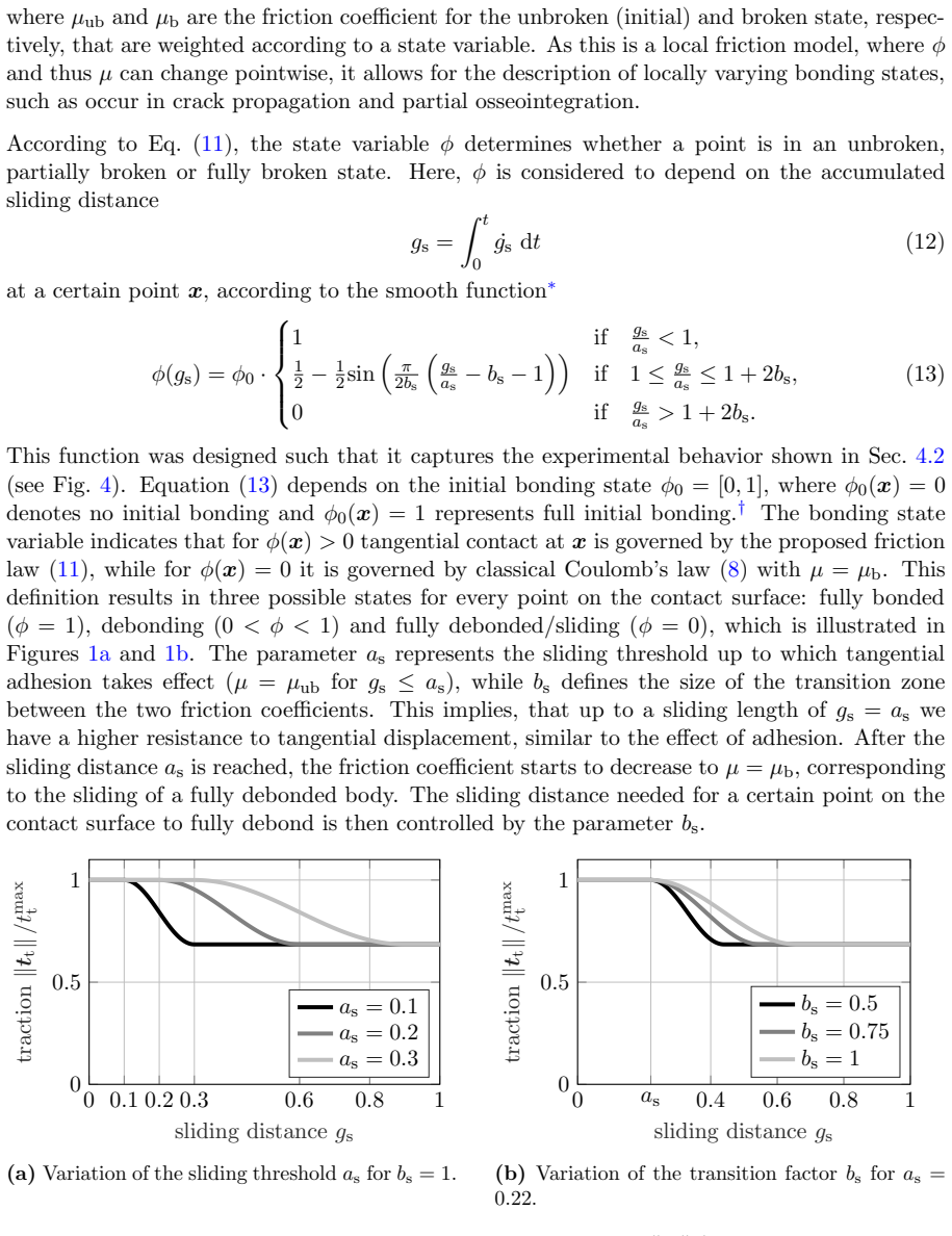
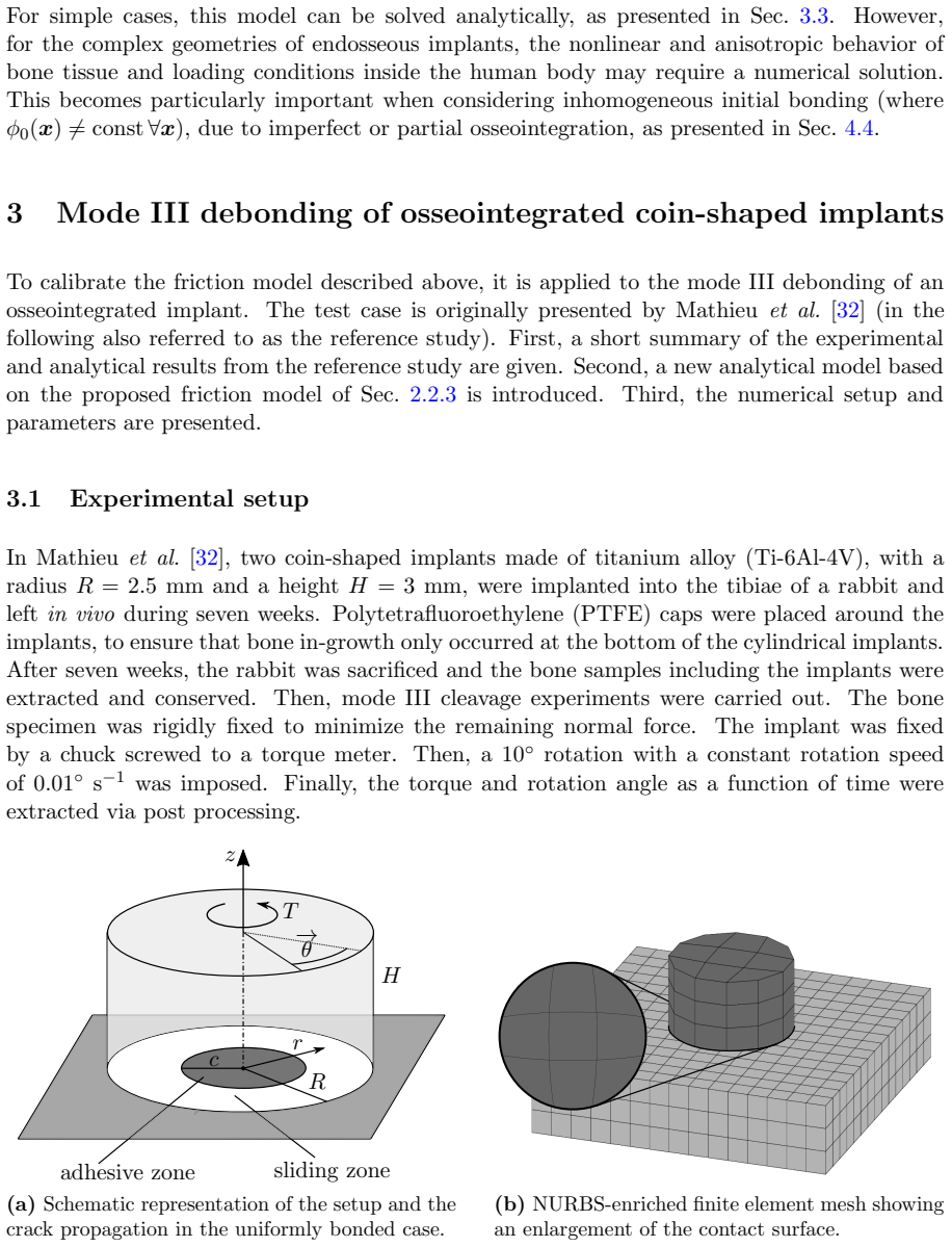
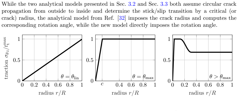
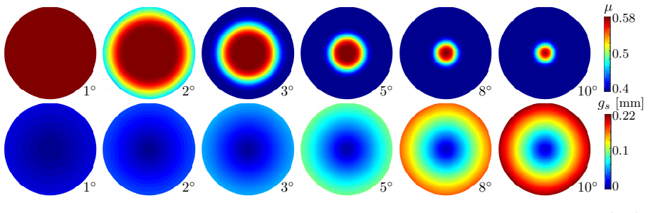
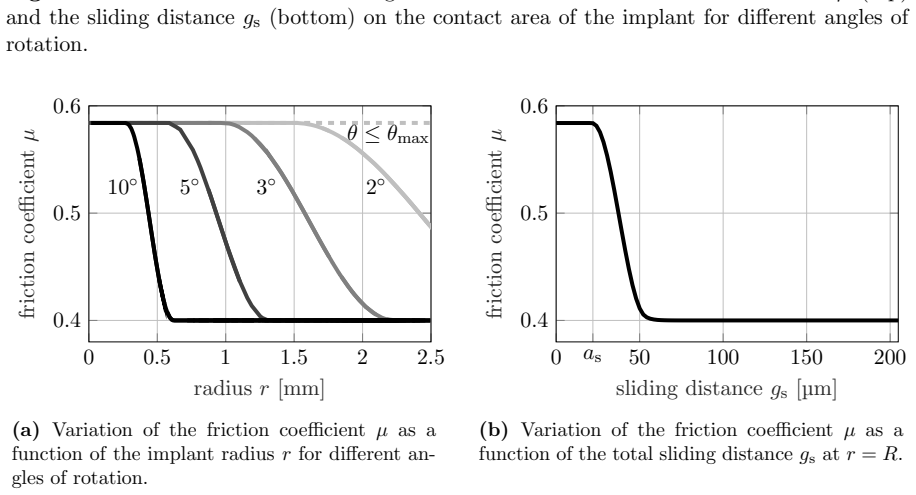
The central object is the modified Coulomb law with a state-dependent friction coefficient, defined by $\mu(\varphi) = \varphi \mu_{\mathrm{ub}} + (1-\varphi)\mu_{\mathrm{b}}$ and the smooth state function $\varphi(g_s) = \varphi_0$ times a sinusoidal plateau–transition–zero profile in the normalized sliding distance $g_s/a_s$. This law converts Coulomb's friction into a local, history-dependent model that can represent a moving crack front and nonuniform bonding. It is implemented in a 3D nonlinear finite element framework with NURBS-enriched contact surfaces and also solved analytically for a radially symmetric mode III debonding, giving the traction distribution $\sigma_{\theta z} = t_{\max}^t r/c(\theta)$ in the sticking region and $\sigma_{\theta z} = \mu p$ in the sliding region.
What would settle it
Measure the normal contact pressure independently during a torsion debonding test, or run the test under controlled zero normal load, and check whether the fully debonded torque equals $T_\infty = \frac{2}{3}\pi R^3 \mu_b p$ with the calibrated friction coefficient; a mismatch, or a nonzero peak under zero pressure, would indicate that the interface resistance is not purely Coulomb-type friction with the proposed sliding-distance decay.
Extended reading notes
Core claim
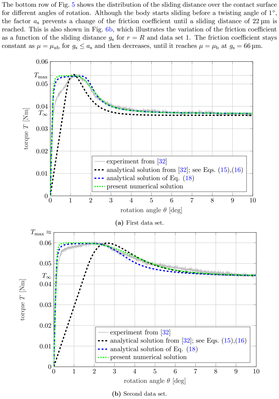
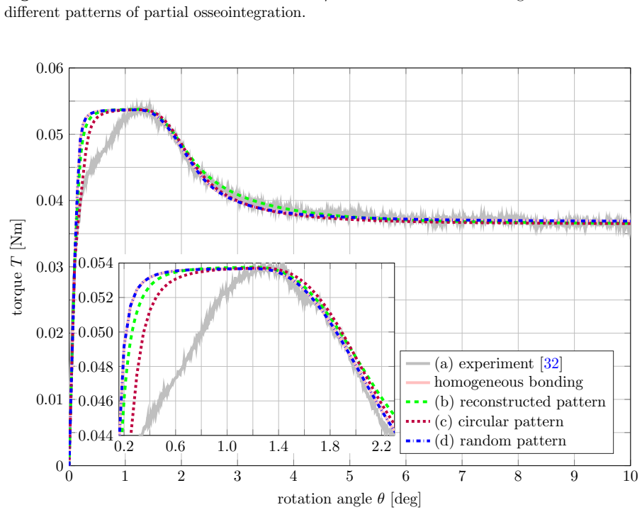
The central claim is that a state-variable friction law of the form $\mu(\varphi) = \varphi \mu_{\mathrm{ub}} + (1-\varphi)\mu_{\mathrm{b}}$, with $\varphi$ a smooth function of the accumulated sliding distance $g_s$, reproduces the full torque-angle response of an osseointegrated implant undergoing torsional debonding. The state function $\varphi(g_s)$ stays at 1 up to a sliding threshold $a_s$, then decays sinusoidally to 0 over a transition zone set by $b_s$. This turns the friction coefficient into a local, history-dependent quantity that describes the progressive loss of bonding. Calibrated against two experimental data sets, the model matches the initial stiffness, peak torque, softening branch, and residual torque, with mean relative errors below 2.25%, and yields bone shear moduli of 7–8 GPa and Young's moduli of 18–21 GPa, which are consistent with literature values, unlike the reference analytical model. The model also shows that partial osseointegration changes the extracted parameters but that the torque curve alone cannot uniquely determine the degree or distribution of osseointegration without knowing the friction coefficients.
Load-bearing premise
The model assumes that the resistance of the osseointegrated interface is governed by Coulomb friction with a decaying friction coefficient, and that the normal pressure $p$ entering that law is real and identifiable from the torque data—but the experiments could not measure or eliminate $p$, and the intact state is treated as high-friction rather than as an adhesive or cohesive interface.
Editorial extensions
If this is right
- The same set of four calibrated parameters ($\mu_{\mathrm{ub}}$, $p$, $a_s$, $b_s$) together with a literature value of $\mu_{\mathrm{b}}$ reproduces the entire torque curve, so the model can serve as a predictive tool for torsional debonding of planar implants.
- The model extracts bone shear modulus and adhesion energy more accurately than the previous analytical model, giving values consistent with independent measurements of cortical bone.
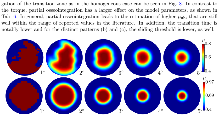
- Because the state variable is local, the model naturally handles partial and inhomogeneous osseointegration, which is common after short healing times.
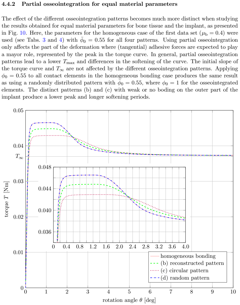
- The torque-angle curve alone does not uniquely determine the distribution of osseointegration when friction coefficients are unknown, implying that additional measurements are needed for full characterization.
- Under perfect twisting, the sliding distance at the center of the implant remains zero, so that point never debonds; this is a prediction about the crack-front arrest that could be checked experimentally.
Reading between the lines
- The sliding threshold $a_s$ (about 22–26 µm here) may correspond to the clinically reported micro-motion tolerance of the bone–implant interface, suggesting a direct link between the friction-state parameter and biological tolerance limits.
- The same state-variable philosophy could be extended to other loading modes such as pull-out or push-in, where the accumulated sliding distance would again drive the transition from bonded to frictional response.
- Since the pressure $p$ is inferred but not measured, a natural testable extension is to design an experiment with independently measured normal force; such a test would either validate the identified pressure or reveal that the unbroken resistance is dominated by adhesion rather than friction.
- The success of a single scalar state variable suggests that complex micro-mechanical adhesion and interlocking processes can be effectively coarse-grained into a history-dependent friction coefficient, which could simplify patient-specific implant stability simulations.
Signed reviews
Editorial analysis
A structured set of objections, weighed in public.
Referee Report
Summary. The paper proposes a Modified Coulomb's law with a state-variable friction coefficient that decays as a function of accumulated sliding distance (Eqs. (11)-(13)) to describe the tangential debonding of osseointegrated implants. The law is implemented in a 3D nonlinear finite element framework and in a new analytical model (Sec. 3.3, Appendix B) for mode III cleavage of a coin-shaped titanium implant, and is calibrated against two experimental torque-angle datasets from Mathieu et al. [32]. The numerical results reproduce the experimental curves with a mean relative error below 2.25% (Table 4), and the paper reports improved estimates of the bone shear modulus and adhesion energy compared with the reference analytical model.
Significance. If the proposed law is accepted, it offers a simple and computationally efficient way to model the transition from intact osseointegration to frictional sliding, and the FE implementation naturally handles partial osseointegration patterns. The paper is thorough in its parameter studies and mesh convergence analysis, and it explicitly lists the limitations of the experimental data. However, the central claim is weakened by the fact that the reported errors are in-sample calibration errors and by an error in the analytical derivation that calls the analytical torque curves into question.
major comments (4)
- [Appendix B, Eq. (49)] The accumulated sliding distance in the sliding region is incorrect. For a point at radius r, sliding begins at θ_start = θlin R/r, so the physical sliding distance is g_s = r(θ - θ_start) = rθ - θlin R. The paper's expression g_s = r(θ - θmax + θlin) is negative for a significant range of θ (for data set 1, for θ between 0.13° and 1.0° at r = R) and yields zero at θ = 1.0°, whereas the correct value is approximately 38 μm at θ = 1.0°. Since Eq. (18) places all points with r ≥ c(θ) in the sliding region, the analytical torque curves in Fig. 4 labeled 'ana. Eq. (18)' are not valid consequences of the proposed friction law. The analytical errors of 2.18% and 2.83% are therefore expressed relative to a model that is inconsistently derived.
- [Sec. 4.1, Eq. (19), Table 4] The parameters μub, as, bs, d, and Gb are determined by minimizing the mean relative error defined in Eq. (19) on the very same experimental curves that are later used to report the error values. The statement that the model reproduces the experimental curves 'with a relative error of less than 2.25%' is thus an in-sample calibration error, not a measure of predictive accuracy. With approximately five free parameters fitted to a single torque curve per data set, the close agreement is to be expected. The paper should state this explicitly and, if possible, provide a validation on an independent data set (e.g., one of the two datasets held out during calibration) to support the claim of predictive power.
- [Sec. 4.5, Table 4] Because the contact pressure p is not measured and is instead generated by an imposed displacement d that is itself calibrated from the same torque data, the friction coefficients μub and μb are not individually identifiable; only the products μub p and μb p are determined. The paper acknowledges that no statement can be made about the accuracy of p, but it still reports μub values with three significant digits and interprets them as physiological parameters. The authors should discuss the non-identifiability more explicitly and perhaps report the results in terms of μ p or provide bounds on p from independent measurements.
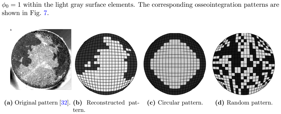
- [Sec. 4.3 vs. Sec. 4.4] The average initial osseointegration fraction for the first data set is given as φ̄0 = 0.73 in Sec. 4.3 (and used in Eq. (21) and Table 5), while Sec. 4.4 states that 'the sample in Fig. 7a is considered to have average osseointegration φ̄0 = 0.55' for the reconstructed pattern. This discrepancy is not explained and changes the computed values of the area-specific work of adhesion substantially. The authors need to clarify which value is used and why the same photograph yields two different estimates.
minor comments (5)
- [Sec. 4.5] 'Circular friction law' is a typo; it should likely read 'Coulomb friction law' or 'state-variable friction law'.
- [Sec. 3.3] The statement 'c≥r≥R denotes the sliding region' contains a reversed inequality; it should read 'c ≤ r ≤ R' since the critical radius c separates the sticking region r < c from the sliding region r ≥ c.
- [Abstract] The phrase 'relative error of less than 2.25%' should specify that this applies to the numerical solution; the analytical solution errors are 2.18% and 2.83%.
- [Table 4] The rows labeled 'ana. [32]' report errors for the reference analytical model; clarifying this in the caption would avoid confusion with the new analytical model.
- [Sec. 4.4] The sentence 'The model only depends on four physiological parameters (µub, p, as, and bs)' treats the contact pressure p as a parameter; p is a mechanical field rather than a physiological parameter, and µb is also fixed from literature.
Circularity Check
The headline <2.25% agreement is an in-sample error on the same torque curves used to fit all friction parameters; the reported shear modulus and adhesion energy are derived from the same fitted curve.
-
fitted input called prediction
[Sec. 4.1, Eq. (19); Sec. 4.2, Fig. 4 and Tab. 4]
"The remaining parameters Gb, d, µub, as, bs are determined by minimizing the mean relative error emp T = mean θ∈[0◦,10◦] (|Texp(θ)−T(θ)|/Texp(θ)) (19) ... Finally, the parameters as and bs are then determined by minimizing Eq. (19) for the whole torque-per-angle curve."
The reported peak/softening agreement (<2.25%, Tab. 4) is the value of the same objective function (19) that is minimized to select d, µub, as, and bs. The torque curves in Fig. 4 are therefore least-squares fits to the very experimental curves they are claimed to 'reproduce'. No hold-out data or cross-validation is used, so the residual is a training error, not an independent prediction.
-
self definitional
[Sec. 2.2.3, Eq. (13)]
"This function was designed such that it captures the experimental behavior shown in Sec. 4.2 (see Fig. 4)."
The smooth state function φ(gs) in Eq. (13) controls the entire shape of the torque peak and softening. It is explicitly designed to match the experimental torque behavior that is later presented as the model's successful reproduction of the experiments. The target behavior is thereby built into the model definition rather than derived from independent first principles.
2 more flagged steps
-
fitted input called prediction
[Sec. 4.3, Eqs. (20)-(21), Tab. 5]
"Edeb = ∫_{θ=0◦}^{10◦} T(θ) dθ, E fric = ∫_{θ=θmax}^{10◦} T∞ dθ, W adh = Edeb−Efric. (20) ... The area-specific average work of adhesion ¯wadh is then given by ¯wadh = Wadh/(πR² ¯φ0). (21)"
The 'very good agreement' for the adhesion energy (e.g. 98 N/m for data set 1) is obtained by integrating the torque curve T(θ) produced with parameters fitted to minimize Eq. (19) on the same experimental curve. Wadh is therefore a functional of the fitted curve, and ¯φ0 is taken from the same post-test implant images, so the agreement is inherited from the calibration rather than being an independent estimate.
-
fitted input called prediction
[Sec. 4.1; Sec. 4.2, Tab. 3]
"The shear modulus Gb is calibrated using the initial slope of the linear part of the torque-per-angle curve (i.e. T (θ ≤ θlin)) ... The estimated shear moduli of 7 and 8 GPa are higher than the reported values of 2–6 GPa [48, 53]), while the corresponding Young’s moduli of 18 and 21 GPa are in good agreement with experimental data from the literature."
The bone shear modulus is read off from the slope of the same experimental torque curve that the model is said to reproduce. Comparing this fitted value with literature values and calling it a 'better estimate' than Ref. [32] is a statement about the calibration, not an independent validation of the friction model, since the initial stiffness is enforced by the fit.
full rationale
The central derivation is a parameter-calibration exercise rather than an independent prediction. Every input of the modified Coulomb model (d, µub, as, bs) is chosen by minimizing Eq. (19) on the full experimental torque curve, and the reported errors are the minimized values of that same objective; the shear modulus is taken from the initial slope of the same curve and the adhesion energy is the integral of the fitted curve. These are standard identifiability and calibration statements, but presenting them as 'predictions' or 'better estimates' reduces the claimed verification to in-sample fit quality. The paper itself concedes that 'no a-priori determination of the input parameters can be made yet' and that the contact pressure required by the Coulomb law could not be measured or eliminated (Sec. 4.5), which reinforces that the extracted parameters are not independently identifiable. The self-citations to Duong/Sauer and Corbett/Sauer concern the contact finite-element machinery and are not load-bearing for the debonding claim. A separate correctness risk is the apparent kinematic inconsistency in Appendix B Eq. (49) for the analytical sliding distance, but that is an error concern, not a circularity, so it is not scored here. Overall, the paper contains several fitted-inputs-called-predictions, giving partial circularity with score 6.
Assumptions & free parameters
free parameters (7)
- mu_b (broken-state friction coefficient) =
0.4 (chosen from literature range 0.2-0.5)
- d (imposed vertical displacement generating contact pressure) =
4.9 um (data set 1), 5.1 um (data set 2) at mu_b=0.4
- mu_ub (unbroken-state friction coefficient) =
0.58 (data set 1), 0.55 (data set 2) at mu_b=0.4
- a_s (sliding threshold) =
22 um (data set 1), 26 um (data set 2)
- b_s (transition zone factor) =
0.74 (data set 1), 1.86 (data set 2)
- G_b (bone shear modulus) =
7 GPa (data set 1), 8 GPa (data set 2)
- phi0_bar (average initial osseointegration fraction) =
0.73 (data set 1), 0.72 (data set 2), 0.55 in partial cases
assumptions (9)
- domain assumption Bone and implant are hyperelastic Neo-Hookean with isotropic response (Eq. (1)).
- domain assumption In the analytical model, bone and implant are linear elastic.
- domain assumption Normal contact pressure is homogeneous in the analytical model.
- domain assumption In the numerical model, a uniform vertical displacement d creates a normal pressure p that is sufficient for friction.
- ad hoc to paper The state variable phi depends only on accumulated sliding distance, not on slip rate or pressure.
- domain assumption Crack and debonding front propagates circularly from the outer radius toward the center.
- domain assumption Main calibration assumes full initial bonding phi0=1.
- domain assumption The fully debonded torque T_infinity is reached at 10 degrees.
- domain assumption Poisson ratio of bone is fixed to nu=0.3.
Cite this review
Pith. "Pith review of A modified Coulomb's law for the tangential debonding of osseointegrated implants." pith.science (2026). https://pith.science/paper/MFBA744Q
@misc{pith2026190804739,
  author       = {Pith},
  title        = {Pith review of: A modified Coulomb's law for the tangential debonding of osseointegrated implants},
  year         = {2026},
  howpublished = {\url{https://pith.science/paper/MFBA744Q}},
  note         = {Machine review of arXiv:1908.04739}
}
read the original abstract
Cementless implants are widely used in orthopedic and oral surgery. However, debonding-related failure still occurs at the bone-implant interface. It remains difficult to predict such implant failure since the underlying osseointegration phenomena are still poorly understood. Especially in terms of friction and adhesion at the macro-scale, there is a lack of data and reliable models. The aim of this work is to present a new friction formulation that can model the tangential contact behavior between osseointegrated implants and bone tissue, with focus on debonding. The classical Coulomb's law is combined with a state variable friction law to model a displacement-dependent friction coefficient. A smooth state function, based on the sliding distance, is used to model implant debonding. The formulation is implemented in a 3D nonlinear finite element framework, and it is calibrated with experimental data and compared to an analytical model for mode III cleavage of a coin-shaped, titanium implant (Mathieu et al. 2012). Overall, the results show close agreement with the experimental data, especially the peak and the softening part of the torque curve with a relative error of less than 2.25 %. In addition, better estimates of the bone's shear modulus and the adhesion energy are obtained. The proposed model is particularly suitable to account for partial osseointegration, as is also shown.
Figures
Figures from the paper (10 more)

Reference graph
Works this paper leans on
-
[32]
V. Mathieu, R. Vayron, E. Barthel, D. Dalmas, E. Soffer, F. Anagnostou, and G. Ha¨ ıat. Mode III cleavage of a coin–shaped titanium implant in bone: Effect of friction and crack propagation. Journal of the Mechanical Behavior of Biomedical Materials , 8(1):194–203, 2012
work page 2012
-
[1]
T. Albrektsson, P. Br˚ anemark, H. Hansson, and J. Lindstr¨ om. Osseointegrated titanium implants: requirements for ensuring a long-lasting, direct bone-to-implant anchorage in man. Acta Orthopaedica Scandinavica, 52(2):155–170, 1981
work page 1981
-
[2]
S. Berahmani, D. Janssen, S. van Kessel, D. Wolfson, M. de Waal Malefijt, P. Buma, and N. Verdonschot. An experimental study to investigate biomechanical aspects of the initial 24 stability of press-fit implants. Journal of the Mechanical Behavior of Biomedical Materials , 42:177–185, 2015
work page 2015
-
[3]
J. E. Biemond, R. Aquarius, N. Verdonschot, and P. Buma. Frictional and bone in- growth properties of engineered surface topographies produced by electron beam tech- nology. Archives of Orthopaedic and Trauma Surgery , 131(5):711–718, 2011
work page 2011
-
[4]
N. E. Bishop, J.-C. H¨ ohn, S. Rothstock, N. B. Damm, and M. M. Morlock. The influence of bone damage on press-fit mechanics. Journal of Biomechanics , 47(6):1472–1478, 2014
work page 2014
-
[5]
M. J. Borden, M. A. Scott, J. A. Evans, and T. J. R. Hughes. Isogeometric finite element data structures based on Bezier extraction of NURBS. International Journal of Numerical Methods in Engineering, 85(1):15–47, 2011
work page 2011
-
[6]
C. Bragdon, D. Burke, J. Lowenstein, D. O’Connor, B. Ramamurti, M. Jasty, and W. Har- ris. Differences in stiffness of the interface between a cementless porous implant and can- cellous bone in vivo in dogs due to varying amounts of implant motion. The Journal of Arthroplasty, 11(8):945–951, 1996
work page 1996
-
[7]
R. Br˚ anemark, L. O. Ohrnell, P. Nilsson, and P. Thomsen. Biomechanical characterization of osseointegrazion during healing: an experimental in vitro study in the rat. Biomaterials, 18:969–978, 1997
work page 1997
Show all 60 references
-
[8]
Br˚ anemark, L.-O.¨Ohrnell, R
R. Br˚ anemark, L.-O.¨Ohrnell, R. Skalak, L. Carlsson, and P.-I. Br˚ anemark. Biomechanical characterization of osseointegration: an experimental in vivo investigation in the beagle dog. Journal of Orthopaedic Research, 16(1):61–69, 1998
1998
-
[9]
Castellani, R
C. Castellani, R. A. Lindtner, P. Hausbrandt, E. Tschegg, S. E. Stanzl-Tschegg, G. Zanoni, S. Beck, and A.-M. Weinberg. Bone–implant interface strength and osseointegration: Biodegradable magnesium alloy versus standard titanium control. Acta Biomaterialia , 7(1):432–440, 2011
2011
-
[10]
Chateauminois, C
A. Chateauminois, C. Fretigny, and L. Olanier. Friction and shear fracture of an adhesive contact under torsion. Physical Review E, 81(2):026106, 2010
2010
-
[11]
Chong, U
D. Chong, U. Hansen, and A. Amis. Analysis of bone–prosthesis interface micromotion for cementless tibial prosthesis fixation and the influence of loading conditions. Journal of Biomechanics, 43(6):1074–1080, 2010
2010
-
[12]
C. J. Corbett and R. A. Sauer. NURBS-enriched contact finite elements.Computer Methods in Applied Mechanics and Engineering , 275:55–75, 2014
2014
-
[13]
C. J. Corbett and R. A. Sauer. Three-dimensional isogeometrically enriched finite elements for frictional contact and mixed-mode debonding. Computer Methods in Applied Mechanics and Engineering, 284:781–806, 2015
2015
-
[14]
N. Damm, M. Morlock, and N. Bishop. Friction coefficient and effective interference at the implant-bone interface. Journal of Biomechanics , 48(12):3517–3521, 2015
2015
-
[15]
Dammak, A
M. Dammak, A. Shirazi-Adl, and D. Zukor. Analysis of cementless implants using inter- face nonlinear friction–experimental and finite element studies. Journal of Biomechanics , 30(2):121–129, 1997
1997
-
[16]
J. H. Dieterich. Time-dependent friction and the mechanics of stick-slip. In Rock Friction and Earthquake Prediction, pages 790–806. Springer, 1978. 25
1978
-
[17]
J. H. Dieterich. Modeling of rock friction: 1. experimental results and constitutive equa- tions. Journal of Geophysical Research: Solid Earth , 84(B5):2161–2168, 1979a
-
[18]
T. X. Duong and R. A. Sauer. A concise frictional contact formulation based on surface potentials and isogeometric discretization. Computational Mechanics, 64(4):951–970, 2019
2019
-
[19]
Fitzpatrick, P
C. Fitzpatrick, P. Hemelaar, and M. Taylor. Computationally efficient prediction of bone– implant interface micromotion of a cementless tibial tray during gait. Journal of Biome- chanics, 47(7):1718–1726, 2014
2014
-
[20]
X. Gao, M. Fraulob, and G. Haiat. Biomechanical behaviours of the boneimplant interface: a review. Journal of the Royal Society Interface , 16(156):20190259, 2019
2019
-
[21]
Ghosh and S
R. Ghosh and S. Gupta. Bone remodelling around cementless composite acetabular com- ponents: The effects of implant geometry and implant–bone interfacial conditions. Journal of the Mechanical Behavior of Biomedical materials , 32:257–269, 2014
2014
-
[22]
J. A. Grant, N. E. Bishop, N. G¨ otzen, C. Sprecher, M. Honl, and M. M. Morlock. Artificial composite bone as a model of human trabecular bone: the implant–bone interface. Journal of Bomechanics, 40(5):1158–1164, 2007
2007
-
[23]
Ha¨ ıat, H.-L
G. Ha¨ ıat, H.-L. Wang, and J. Brunski. Effects of biomechanical properties of the bone– implant interface on dental implant stability: from in silico approaches to the patient’s mouth. Annual Review of Biomedical Engineering , 16:187–213, 2014
2014
-
[24]
T. J. R. Hughes, J. A. Cottrell, and Y. Bazilevs. Isogeometric analysis: CAD, finite elements, NURBS, exact geometry and mesh refinement. Computer Methods in Applied Mechanics and Engineering, 194(1):4135–4195, 2005
2005
-
[25]
Jasty, C
M. Jasty, C. Bragdon, D. Burke, D. O’connor, J. Lowenstein, and W. Harris. In vivo skeletal responses to porous-surfaced implants subjected to small induced motions. Journal of Bone and Joint Surgery , 79(5):707–14, 1997
1997
-
[26]
Kim, J.-H
S.-H. Kim, J.-H. Cho, K.-R. Chung, Y.-A. Kook, and G. Nelson. Removal torque val- ues of surface-treated mini-implants after loading. American Journal of Orthodontics and Dentofacial Orthopedics, 134(1):36–43, 2008
2008
-
[27]
T. A. Laursen. Computational contact and impact mechanics: fundamentals of modeling interfacial phenomena in nonlinear finite element analysis . Springer Science & Business Media, 2013
2013
-
[28]
T. A. Laursen and J. C. Simo. A continuum-based finite element formulation for the implicit solution of multibody, large deformation frictional contact problems. International Journal for Numerical Methods in Engineering , 36(1):3451–3485, 1993
1993
-
[29]
Marin, R
C. Marin, R. Granato, M. Suzuki, M. N. Janal, et al. Biomechanical and histomorphometric analysis of etched and non-etched resorbable blasting media processed implant surfaces: an experimental study in dogs. Journal of the Mechanical Behavior of Biomedical Materials , 3(5):382...
2010
-
[30]
Mathieu, F
V. Mathieu, F. Anagnostou, E. Soffer, and G. Ha¨ ıat. Ultrasonic evaluation of dental implant biomechanical stability: an in vitro study. Ultrasound in Medicine & Biology , 37(2):262–270, 2011a. 26
-
[31]
Mathieu, F
V. Mathieu, F. Anagnostou, E. Soffer, and G. Ha¨ ıat. Numerical simulation of ultrasonic wave propagation for the evaluation of dental implant biomechanical stability.The Journal of the Acoustical Society of America , 129(6):4062–4072, 2011b
-
[33]
Mathieu, R
V. Mathieu, R. Vayron, G. Richard, G. Lambert, S. Naili, J. Meningaud, and G. Ha¨ ıat. Biomechanical determinants of the stability of dental implants: Influence of the bone– implant interface properties. Journal of Biomechanics , 47(1):3–13, 2014
2014
-
[34]
J. C. Mergel, R. Sahli, J. Scheibert, and R. A. Sauer. Continuum contact models for coupled adhesion and friction. The Journal of Adhesion , 95(12):1101–1133, 2019
2019
-
[35]
Novitskaya, P
E. Novitskaya, P. Chen, E. Hamed, L. Jun, V. A. Lubarda, I. Jasiuk, and J. McKittrick. Recent advances on the measurement and calculation of the elastic moduli of cortical and trabecular bone: a review. Theoretical and Applied Mechanics, 38(3):209–297, 2011
2011
-
[36]
S. H. Pettersen, T. S. Wik, and B. Skallerud. Subject specific finite element analysis of implant stability for a cementless femoral stem. Clinical Biomechanics, 24(6):480–487, 2009
2009
-
[37]
Pilliar, J
R. Pilliar, J. Lee, and C. Maniatopoulos. Observations on the effect of movement on bone ingrowth into porous-surfaced implants. Clinical Orthopaedics and Related Research, 208:108–113, 1986
1986
-
[38]
Rancourt, A
D. Rancourt, A. Shirazi-Adl, G. Drouin, and G. Paiement. Friction properties of the interface between porous-surfaced metals and tibial cancellous bone. Journal of Biomedical Materials Research Part A , 24(11):1503–1519, 1990
1990
-
[39]
J. Y. Rho, R. B. Ashman, and C. H. Turner. Young’s modulus of trabecular and corti- cal bone material: ultrasonic and microtensile measurements. Journal of Biomechanics , 26(2):111–119, 1993
1993
-
[40]
Rice and A
J. Rice and A. L. Ruina. Stability of steady frictional slipping. Journal of Applied Me- chanics, 50(2):343–349, 1983
1983
-
[41]
Rittel, A
D. Rittel, A. Dorogoy, and K. Shemtov-Yona. Modeling the effect of osseointegration on dental implant pullout and torque removal tests. Clinical Implant Dentistry and Related Research, 20(5):683–691, 2018
2018
-
[42]
H. J. Rønold and J. E. Ellingsen. The use of a coin shaped implant for direct in situ mea- surement of attachment strength for osseointegrating biomaterial surfaces. Biomaterials, 23(10):2201–2209, 2002
2002
-
[43]
H. J. Rønold, S. P. Lyngstadaas, and J. E. Ellingsen. Analysing the optimal value for tita- nium implant roughness in bone attachment using a tensile test.Biomaterials, 24(25):4559– 4564, 2003
2003
-
[44]
A. Ruina. Slip instability and state variable friction laws. Journal of Geophysical Research: Solid Earth, 88(B12):10359–10370, 1983
1983
-
[45]
R. A. Sauer. Enriched contact finite elements for stable peeling computations. International Journal for Numerical Methods in Engineering , 87(6):593–616, 2011. 27
2011
-
[46]
R. A. Sauer and L. D. Lorenzis. A computational contact formulation based on surface potentials. Computer Methods in Applied Mechanics and Engineering , 253:369–395, 2013
2013
-
[47]
R. A. Sauer and L. D. Lorenzis. An unbiased computational contact formulation for 3d friction. International Journal for Numerical Methods in Engineering , 101(4):251–280, 2015
2015
-
[48]
N. K. Sharma, D. K. Sehgal, and R. K. Pandey. Comparative study of locational variation in shear and transverse elastic modulus of buffalo cortical bone. IERI Procedia, 1:205–210, 2012
2012
-
[49]
Shirazi-Adl
A. Shirazi-Adl. Finite element stress analysis of a push-out test part 1: fixed interface using stress compatible elements. Journal of Biomechanical Engineering , 114(1):111–118, 1992
1992
-
[50]
Shirazi-Adl, M
A. Shirazi-Adl, M. Dammak, and G. Paiement. Experimental determination of friction characteristics at the trabecular bone and porous-coated metal interface in cementless implants. Journal of Biomedical Materials Research Part A , 27(2):167–175, 1993
1993
-
[51]
Skripitz and P
R. Skripitz and P. Aspenberg. Attachment of PMMA cement to bone: force measurements in rats. Biomaterials, 20(4):351–356, 1999
1999
-
[52]
Y. Sul, C. Johansson, Y. Jeong, K. R¨ oser, A. Wennerberg, and T. Albrektsson. Oxidized implants and their influence on the bone response. Journal of Materials Science: Materials in Medicine, 12(10-12):1025–1031, 2001
2001
-
[53]
T. Tang, V. Ebacher, P. Cripton, P. Guy, H. McKay, and R. Wang. Shear deformation and fracture of human cortical bone. Bone, 71:25–35, 2015
2015
-
[54]
Tschegg, R
E. Tschegg, R. Lindtner, V. Doblhoff-Dier, S. Stanzl-Tschegg, G. Holzlechner, C. Castel- lani, T. Imwinkelried, and A. Weinberg. Characterization methods of bone–implant- interfaces of bioresorbable and titanium implants by fracture mechanical means. Journal of the Mechanical B...
2011
-
[55]
Vayron, E
R. Vayron, E. Barthel, V. Mathieu, E. Soffer, F. Anagnostou, and G. Ha¨ ıat. Variation of biomechanical properties of newly formed bone tissue determined by nanoindentation as a function of healing time. Computer Methods in Biomechanics and Biomedical Engineering, 14(sup1):139–...
2011
-
[56]
Vayron, E
R. Vayron, E. Barthel, V. Mathieu, E. Soffer, F. Anagnostou, and G. Ha¨ ıat. Nanoinden- tation measurements of biomechanical properties in mature and newly formed bone tissue surrounding an implant. Journal of Biomechanical Engineering , 134(2):021007, 2012
2012
-
[57]
Wennerberg, R
A. Wennerberg, R. Jimbo, S. St¨ ubinger, M. Obrecht, M. Dard, and S. Berner. Nanostruc- tures and hydrophilicity influence osseointegration: a biomechanical study in the rabbit tibia. Clinical Oral Implants Research, 25(9):1041–1050, 2014
2014
-
[58]
Wriggers
P. Wriggers. Computational contact mechanics. Springer Science & Business Media, 2006
2006
-
[59]
Zhang, P
Y. Zhang, P. B. Ahn, D. C. Fitzpatrick, A. D. Heiner, R. A. Poggie, and T. D. Brown. Interfacial frictional behavior: cancellous bone, cortical bone, and a novel porous tantalum biomaterial. Journal of Musculoskeletal Research , 3(04):245–251, 1999
1999
-
[60]
Zienkiewicz and R
O. Zienkiewicz and R. Taylor. The finite element method for solid and structural mechanics. Butterworth–Heinemann, 2005. 28
2005
Reviewed August 14, 2026 · model on record in the stance chip above.
Discussion (0). Continue with ORCID to comment.