REVIEW 5 minor 1 cited by
A Multi-Frequency Input-Admittance Model of Locomotive Rectifier Considering PWM Sideband Harmonic Coupling in Electrical Railways
T0 review · 0 major / 5 minor · reviewed 2026-07-13 · grok-4.5
Pith's one-line read PWM sideband harmonics, not the usual average model, set locomotive rectifier admittance above half the switching frequency, and a converted SISO model captures that coupling for railway stability checks.
desk verdict Solid, measurement-backed multi-frequency admittance for locomotive rectifiers that correctly shows sidebands dominate above half fsw; incremental but clean and useful for railway HIS work. read the letter →
The pith
A machine-rendered reading of the paper's core claim, the machinery that carries it, and where it could break.
The reading
What carries the argument
The three-order PWM transfer-function matrix (G0, G1, G2) that maps a perturbation and its two sideband tones through the digital comparator, together with the subsequent multi-to-SISO admittance conversion that preserves those sideband couplings.
What would settle it
Measure the rectifier input admittance above half the switching frequency with the PLL and voltage loop both closed and both open; if the measured curves diverge significantly from the SISO prediction only when the loops are closed, the omission assumption fails.
Extended reading notes
Core claim
PWM sideband harmonics dominate a locomotive rectifier’s input admittance once the perturbation frequency exceeds half the switching frequency; a three-order multi-frequency admittance that keeps those couplings, when converted to SISO form, is measurably more accurate than the classical averaging model in that range and correctly predicts the onset of high-frequency harmonic instability under changes in switching frequency, control bandwidth, and network impedance.
Load-bearing premise
The phase-locked loop and dc-voltage controller can be left out of the high-frequency model because their bandwidths are low enough that they do not affect the sideband couplings of interest.
Signed reviews
Editorial analysis
A structured set of objections, weighed in public.
Referee Report
Summary. The paper derives a multi-frequency input-admittance model of a locomotive rectifier that accounts for PWM sideband harmonic coupling, then converts it to an equivalent SISO admittance that retains those couplings. Starting from a three-order PWM transfer-function matrix (G0, G1, G2) obtained via 1-D spectrum analysis and harmonic balance, the authors form a closed-loop multi-frequency admittance matrix (Eqs. 19–21) and apply a conversion technique (Eq. 22) to obtain a SISO model usable with classical Nyquist/Bode criteria. Frequency-scan measurements confirm that the sideband terms dominate above half the switching frequency and that the SISO model matches measured admittance better than the classical averaging model in that range. HIL experiments then show how switching frequency, ACC bandwidth, and traction-network impedance shift the L–N stability boundary, with predicted critical frequencies matching observed harmonic content.
Significance. High-frequency harmonic instability is a practical problem in modern electrified railways, and classical averaging models lose validity above half the switching frequency. By retaining PWM sideband couplings in a usable SISO form, the work supplies a concrete, experimentally corroborated tool for stability assessment and parameter design (fsw, control bandwidth, network impedance). The derivation is first-principles, the G0/G1/G2 and Yrec predictions are validated against independent frequency scans, and the HIL results provide falsifiable stability-boundary predictions. These elements make the contribution useful for both analysis and design of L–N systems.
minor comments (5)
- In §III the authors correctly note that PLL and DVC are omitted because of their low bandwidth; a short quantitative remark (e.g., typical bandwidth values relative to the frequencies of interest) would make the approximation’s domain of validity more transparent to readers who may not be railway specialists.
- Equation numbering jumps from (4) to (6); the missing (5) appears to be the sideband-frequency definitions later labeled (6). Renumbering would avoid confusion when citing the sideband relations.
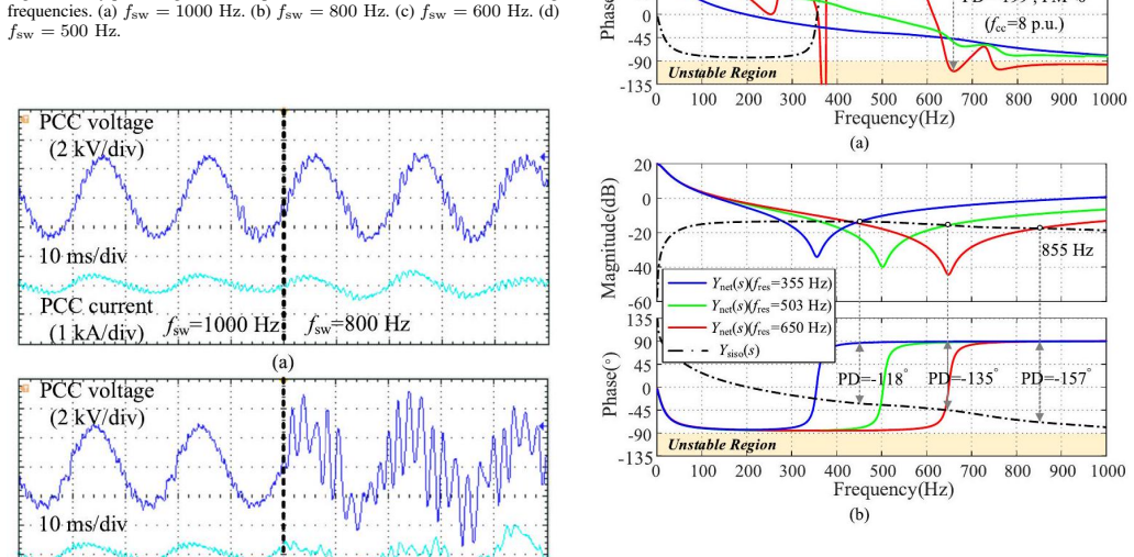
- Fig. 9 and Fig. 10 captions and axis labels would benefit from explicit units (Hz, dB, deg) and a clearer indication of the 1/2-fsw separatrix so that the dominance claim is immediately readable.
- A few typographical inconsistencies remain (e.g., “inputadmittance”, “highfrequency”, “allparallel”, “Zoomedin”). A final copy-edit pass would improve readability.
- Table III lists phase differences and margins; adding a brief note on how the phase margin is computed from the multi-frequency-to-SISO conversion would help readers reproduce the stability conclusions.
Circularity Check
No significant circularity: multi-frequency PWM admittance and SISO conversion are derived from spectrum analysis plus closed-loop equations and validated against independent measurements/HIL.
full rationale
The load-bearing chain begins with the 1-D Fourier/Bessel expansion of the digital PWM process (Eqs. 8–11, Fig. 6), constructs the three-order transfer-function matrix G_pwm (Eqs. 12–14), inserts it into the rectifier closed-loop equations to obtain the multi-frequency admittance matrix Y_rec (Eqs. 19–21), and applies an external MIMO-to-SISO conversion (Eq. 22, citing [21]) that retains the sideband couplings. The resulting SISO model is then compared directly to frequency-response measurements (Figs. 9–10) and used for Nyquist/HIL stability checks under parameter sweeps; none of these steps fit a free parameter to the target data and then re-predict it, nor do they rest on a uniqueness theorem or ansatz imported solely from the authors’ prior papers. Self-citations ([5], [14]–[16]) supply only background low-frequency control bandwidth arguments and traction-network impedance formulas; they are not required for the high-frequency sideband claim that constitutes the paper’s central result. The derivation is therefore self-contained against external benchmarks and exhibits only the ordinary, non-load-bearing self-citation common in the field.
Assumptions & free parameters
assumptions (4)
- domain assumption PLL and DVC dynamics may be neglected for frequencies of interest (above ~250 Hz) because their bandwidths are low.
- domain assumption Only the two sidebands fpwmb1 = fsw – fp – f0 and fpwmb2 = fsw – fp + f0 need be retained; higher-order sidebands and aliasing above Nyquist are negligible.
- standard math The MIMO-to-SISO conversion of Zhang et al. (ref. [21]) preserves the relevant sideband couplings for stability analysis.
- domain assumption Bipolar asymmetric regular sampling with sampling at carrier peaks (fsa = 2 fsw) accurately describes the digital PWM process used on the locomotive.
Cite this review
Pith. "Pith review of A Multi-Frequency Input-Admittance Model of Locomotive Rectifier Considering PWM Sideband Harmonic Coupling in Electrical Railways." pith.science (2026). https://pith.science/paper/MUOSTZIV
@misc{pith2026260709275,
  author       = {Pith},
  title        = {Pith review of: A Multi-Frequency Input-Admittance Model of Locomotive Rectifier Considering PWM Sideband Harmonic Coupling in Electrical Railways},
  year         = {2026},
  howpublished = {\url{https://pith.science/paper/MUOSTZIV}},
  note         = {Machine review of arXiv:2607.09275}
}
read the original abstract
Electrical railway harmonic instability issues are common in the high-frequency range. The effective frequency of the traditional converter's small-signal averaging model is below 1/2 switching frequency since the pulse width modulation (PWM) sideband harmonic components are ignored. In this article, the dynamic propagations of perturbation frequency and the generated PWM sideband components are constructed first. Then the locomotive rectifier's multi-frequency input-admittance model is derived appropriately. Afterward, an admittance conversion approach is used to convert the multi-frequency model into the single-input-single-output (SISO) model whereas retaining the sideband frequency couplings. The proposed SISO model is more accurate than the traditional small-signal averaging model in the frequency range higher than 1 / 2 switching frequency. It is found that PWM sideband harmonics dominate the locomotive rectifier's input-admittance characteristic higher than 1 / 2 switching frequency. Finally, based on the proposed model, the influence of different switching frequencies, control bandwidths, and traction network impedance on system harmonic stability is revealed by the hardware-in-the-loop (HIL) results.
Figures


Figures from the paper (12 more)




Forward citations
Cited by 1 Pith paper
-
High-Resolution Imaging of Plant Delayed Luminescence
A qCMOS camera achieves megapixel imaging of plant delayed luminescence and reveals species-specific spatial patterns, stress responses, and wavelength-dependent kinetics.
Reference graph
Works this paper leans on
-
[1]
High-order harmonic resonances in traction power supplies: A review based on railway operational data, measurements, and experience,
K. Song, W. Mingli, S. Yang, Q. Liu, V . G. Agelidis, and G. Konstantinou, "High-order harmonic resonances in traction power supplies: A review based on railway operational data, measurements, and experience," IEEE Trans. Power Electron., vol. 35, no. 3, pp. 2501-2518, Mar. 2020
2020
-
[2]
Overview of harmonic and resonance in railway electrification systems,
H. Hu, Y . Shao, L. Tang, J. Ma, Z. He, and S. Gao, "Overview of harmonic and resonance in railway electrification systems," IEEE Trans. Ind. Appl., vol. 54, no. 5, pp. 5227-5245, Sep. 2018
2018
-
[3]
Railway Applications-Power Supply and Rolling Stock Technical Criteria for the Coordination Between Power Supply (Substation) and Rolling Stock to Achieve Interoperability," Cenelec Standard EN 50388 Ed.2, 2012
2012
-
[4]
Impedance-based stability criterion for grid- connected inverters,
J. Sun, "Impedance-based stability criterion for grid- connected inverters," IEEE Trans. Power Electron., vol. 26, no. 11, pp. 3075-3078, Nov. 2011
2011
-
[5]
Low-frequency stability analysis of vehiclegrid system with active power filter based ondq-frame impedance,
S. Wu and Z. Liu, "Low-frequency stability analysis of vehiclegrid system with active power filter based ondq-frame impedance," IEEE Trans. Power Electron., vol. 36, no. 8, pp. 9027-9040, Aug. 2021
2021
-
[6]
Multifrequency small-signal model for buck and multiphase buck converters,
Y . Qiu, M. Xu, K. Yao, J. Sun, and F. C. Lee, "Multifrequency small-signal model for buck and multiphase buck converters," IEEE Trans. Power Electron., vol. 21, no. 5, pp. 1185-1192, Sep. 2006
2006
-
[7]
A generic high- frequency model for the nonlinearities in buck converters,
Y . Qiu, M. Xu, J. Sun, and F. C. Lee, "A generic high- frequency model for the nonlinearities in buck converters," IEEE Trans. Power Electron., vol. 22, no. 5, pp. 1970-1977, Sep. 2007
1970
-
[8]
VSC input-admittance modeling and analysis above the Nyquist frequency for passivity-based stability assessment,
L. Harnefors, R. Finger, X. Wang, H. Bai, and F. Blaabjerg, "VSC input-admittance modeling and analysis above the Nyquist frequency for passivity-based stability assessment," IEEE Trans. Ind. Electron., vol. 64, no. 8, pp. 6362-6370, Aug. 2017
2017
Show all 22 references
-
[9]
Multivariable high-frequency input-admittance of grid-connected converters: Modeling, validation, and implications on stability,
F. D. Freijedo, M. Ferrer, and D. Dujic, "Multivariable high-frequency input-admittance of grid-connected converters: Modeling, validation, and implications on stability," IEEE Trans. Ind. Electron., vol. 66, no. 8, pp. 6505-6515, Aug. 2019
2019
-
[10]
Sideband harmonic instability of paralleled inverters with asynchronous carriers,
D. Yang, X. Wang, and F. Blaabjerg, "Sideband harmonic instability of paralleled inverters with asynchronous carriers," IEEE Trans. Power Electron., vol. 33, no. 6, pp. 4571-4577, Jun. 2018
2018
-
[11]
A multifrequency model of electric locomotive for high- frequency instability assessment,
H. Tao, H. Hu, X. Zhu, K. Lei, and Z. He, "A multifrequency model of electric locomotive for high- frequency instability assessment," IEEE Trans. Transport. Electrific., vol. 6, no. 1, pp. 241-256, Mar. 2020
2020
-
[12]
Impact of PWM switching on modeling of low frequency power oscillation in electrical rail vehicle,
H. Y . Assefa, S. Danielsen, and M. Molinas, "Impact of PWM switching on modeling of low frequency power oscillation in electrical rail vehicle," in Proc. 13th Eur. Conf. Power Electron. Appl., Barcelona, Spain, Sep. 2009, pp. 1-9
2009
-
[13]
A matrix-based multifrequency output impedance model for beat frequency oscillation analysis in distributed power systems,
X. Yue, F. Zhuo, S. Yang, Y . Pei, and H. Yi, "A matrix-based multifrequency output impedance model for beat frequency oscillation analysis in distributed power systems," IEEE J. Emerg. Sel. Topics Power Electron., vol. 4, no. 1, pp. 80-92, Mar. 2016
2016
-
[14]
Stability research of high-speed railway EMUs and traction network cascade system considering impedance matching,
Z. Liu, G. Zhang, and Y . Liao, "Stability research of high-speed railway EMUs and traction network cascade system considering impedance matching," IEEE Trans. Ind. Appl., vol. 52, no. 5, pp. 4315-4326, Sep. 2016
2016
-
[15]
A spatial coupling model to study dynamic performance of pantograph- catenary with vehicletrack excitation,
Y . Song, Z. Wang, Z. Liu, and R. Wang, "A spatial coupling model to study dynamic performance of pantograph- catenary with vehicletrack excitation," Mech. Syst. Signal Process., vol. 151, Apr. 2021, Art. no. 107336
2021
-
[16]
Contact wire irregularity stochastics and effect on high- speed railway pantograph-catenary interactions,
Y . Song, Z. Liu, A. Rønnquist, P. Navik, and Z. Liu, "Contact wire irregularity stochastics and effect on high- speed railway pantograph-catenary interactions," IEEE Trans. Instrum. Meas., vol. 69, no. 10, pp. 8196-8206, Oct. 2020. 11
2020
-
[17]
Study on some problems of traction power supply systems in high-speed railway,
Q. Ma, "Study on some problems of traction power supply systems in high-speed railway," Ph.D. dissertation, School Elect. Eng., Southwest Jiaotong Univ., Chengdu, China, 2013
2013
-
[18]
D. G. Holmes and T. A. Lipo, Pulse Width Modulation for Power Converters: Principles and Practice. Hoboken, NJ, USA: Wiley, 2003
2003
-
[19]
One-dimensional spectral analysis of complex PWM waveforms using superposition,
H. D. T. Mouton, B. McGrath, D. G. Holmes, and R. H. Wilkinson, "One-dimensional spectral analysis of complex PWM waveforms using superposition," IEEE Trans. Power Electron., vol. 29, no. 12, pp. 6762-6778, Dec. 2014
2014
-
[20]
A harmonic balance methodology for circuits with fractional and nonlinear elements,
M. Sowa, "A harmonic balance methodology for circuits with fractional and nonlinear elements," Circuits, Syst., Signal Process., vol. 37, no. 11, pp. 4695-4727, Nov. 2018
2018
-
[21]
Harmonicdomain SISO equivalent impedance modeling and stability analysis of a single-phase grid-connected VSC,
C. Zhang, M. Molinas, S. Foyen, J. A. Suul, and T. Isobe, "Harmonicdomain SISO equivalent impedance modeling and stability analysis of a single-phase grid-connected VSC," IEEE Trans. Power Electron., vol. 35, no. 9, pp. 9770-9783, Sep. 2020
2020
-
[22]
Train-network interactions and stability evaluation in high- speed railways-Part II: Influential factors and verifications,
H. Hu, H. Tao, X. Wang, F. Blaabjerg, Z. He, and S. Gao, "Train-network interactions and stability evaluation in high- speed railways-Part II: Influential factors and verifications," IEEE Trans. Power Electron., vol. 33, no. 6, pp. 4643-4659, Jun. 2018
2018
Reviewed July 13, 2026 · model on record in the stance chip above.
Discussion (0). Continue with ORCID to comment.