REVIEW 3 major objections 5 minor 34 references
Design, Modeling, and Control of Norma: a Slider & Pendulum-Driven Spherical Robot
T0 review · 3 major / 5 minor · reviewed 2026-08-14 · deepseek-v4-flash
Pith's one-line read This paper derives the full dynamics of a two-actuator spherical robot and shows, in simulation, that it can roll, turn, and track a smooth path.
desk verdict A novel slider-pendulum spherical robot with a careful EL derivation, but the turning model is imposed kinematically and the validation is self-referential. read the letter →
The pith
A machine-rendered reading of the paper's core claim, the machinery that carries it, and where it could break.
The reading
What carries the argument
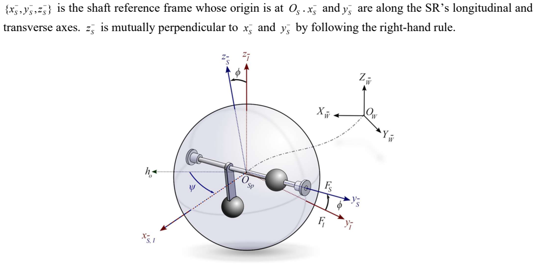
The load-bearing object is the four-coordinate Euler-Lagrange dynamics written in the standard second-order form, together with the rolling-cone kinematic constraint used for turning. The generalized coordinates are $\theta$ (sphere roll about the transverse shaft), $\alpha$ (pendulum rotation about the shaft), $\phi$ (tilt about the longitudinal axis), and $\delta$ (slider displacement along the shaft). The rolling-cone relation supplies yaw rate from roll rate and tilt angle, while the Lagrangian built from the kinetic and potential energies of the sphere, pendulum, and slider supplies the matrices $M$, $C$, and $G$. Christoffel symbols are used to make the Coriolis/centripetal matrix skew-symmetric with $\dot M-2C$. This structure is what lets the authors separate kinematics, handled by pure pursuit, from dynamics, handled by PID tracking of the desired roll rate and slider position.
What would settle it
Lock the slider at a known off-center position so the ball tilts by $\phi$, roll it forward at a roughly constant roll rate $\dot\theta$ on a flat hard floor, and measure the heading $\psi$ over several full revolutions. Compare $\dot\psi$ with $-\dot\theta\,\sin\phi/(R\cos\phi-R\sin\phi)$; a disagreement larger than the measurement error would refute the rolling-cone model and, with it, the derived dynamics and the simulated tracking results.
Extended reading notes
Core claim
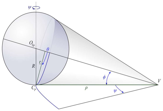
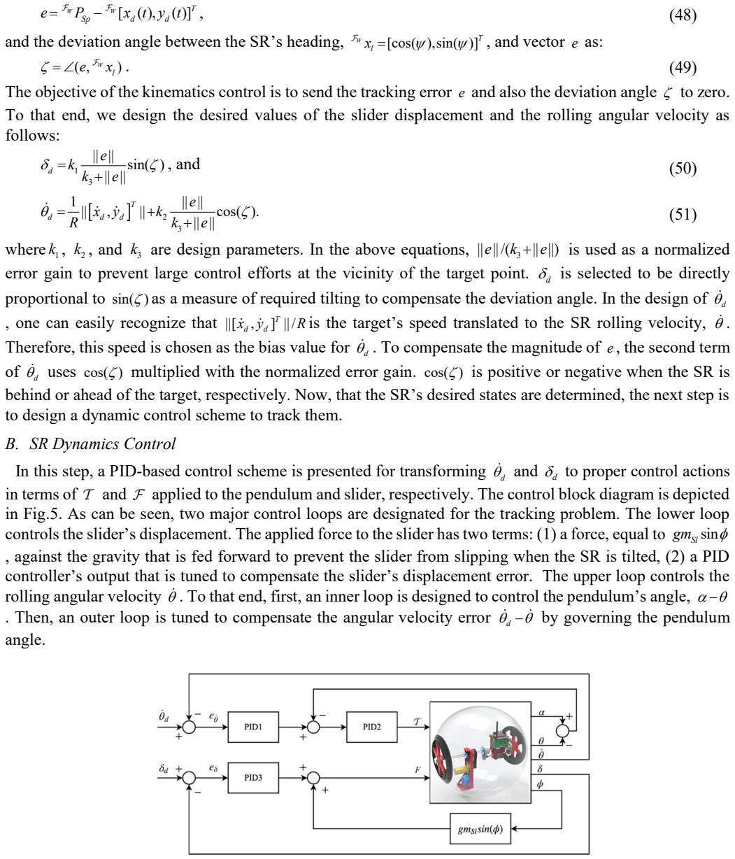
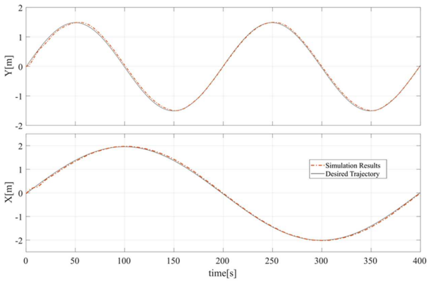
The central claim is that a spherical robot can obtain both rolling and steering from two internal actuators, and that this behavior is captured by a closed Euler-Lagrange model rather than by a simplified or decoupled approximation. The tilt angle $\phi$ is coupled to yaw rate through a rolling-cone relation $\dot\psi=-\dot\theta\,\sin\phi/(R\cos\phi-R\sin\phi)$, so slider motion that changes $\phi$ produces turning, whereas pendulum torque $\Gamma$ drives $\dot\theta$ and hence forward motion. The derived model has the standard robot form $M(q)\ddot q+C(q,\dot q)\dot q+G(q)=\tau$, and the paper constructs the Coriolis/centripetal matrix using Christoffel symbols so that $\dot M-2C$ is skew-symmetric. A pure-pursuit outer loop specifies desired values for $\dot\theta$ and $\delta$, and PID loops generate $\Gamma$ and $\Phi$; simulations show the robot converging to the desired trajectory with tracking error near zero.
Load-bearing premise
The load-bearing premise is that a tilted sphere rolling on flat ground behaves exactly like a solid cone, without slipping, so each roll changes the heading by an amount fixed by the tilt angle; if that geometric rule is wrong, the yaw rate used to build the dynamics and the controller is wrong too.
Editorial extensions
If this is right
- A physical Norma robot would need only the pendulum torque and the slider force as inputs to execute both forward motion and turns on flat ground.
- Because the model is in $M(q)\ddot q+C(q,\dot q)\dot q+G(q)=\tau$ form, standard robot-control techniques such as computed torque, gain scheduling, or adaptive parameter estimation can be applied directly to it.
- The pure-pursuit plus PID architecture gives a decoupled design procedure: choose desired roll speed and slider position from path error, then tune two independent PID loops for the actuators.
- The simulations imply that, with the stated masses, lengths, and PID gains, tracking error converges to a small neighborhood of zero on a smooth path.
- A working two-input design would make spherical robots simpler to build than multi-actuator gimbal or flywheel designs, since steering and propulsion come from the same internal mass shifts.
Reading between the lines
- A direct hardware test of the cone kinematic relation is the fastest way to decide whether the model transfers to a real robot: lock the slider at fixed $\phi$, roll the ball at known $\dot\theta$, and compare measured heading change with $\dot\psi=-\dot\theta\,\sin\phi/(R\cos\phi-R\sin\phi)$.
- The point-mass assumptions for the slider and pendulum bob, plus a massless rod, are convenient for the Lagrangian but will be violated in a physical build; adding those inertias or showing that they are negligible is a natural extension the paper does not address.
- If the ideal no-slip cone model were replaced by a contact model with a finite contact patch and slip, the same control law could be re-evaluated to show how much of the simulated tracking performance depends on the no-slip assumption.
- The control demonstration is limited to smooth trajectories; extending the scheme to paths with corners or to 3D terrain would likely require a modified kinematic law for $\dot\psi$.
Signed reviews
Editorial analysis
A structured set of objections, weighed in public.
Referee Report
Summary. The paper presents the design, dynamics modeling, and control of Norma, a spherical robot actuated by a pendulum and a slider on a diagonal shaft. The authors use the Euler-Lagrange method to derive an explicit 4-DOF model M(q)q̈ + C(q,q̇)q̇ + G(q) = τ with generalized coordinates q = [θ, α, φ, δ], then propose a pure-pursuit kinematic controller together with PID dynamic controllers for the pendulum torque and slider force. The reported contribution is that this 2-actuator mechanism can perform rolling and turning maneuvers, and that MATLAB simulations demonstrate accurate path tracking. The Appendix gives element-wise expressions for M, C, and G, and the Coriolis matrix is constructed via Christoffel symbols so that Ṁ − 2C is skew-symmetric.
Significance. If the derived model and kinematic relations were correct, the paper would be a useful reference for simulation-based control design of pendulum-and-slider spherical robots. The first-principles derivation is detailed, the inertia matrix is symmetric by construction, and the explicit Appendix A is a valuable checkable artifact. However, the turning kinematics rests on an unproven cone analogy, the yaw coordinate is absent from the dynamics, and the 'verification' is a self-simulation of the same model with no independent experimental or model-based benchmark. These issues directly affect the paper's central claim of a complete model that enables turning control, so the current manuscript does not establish that claim.
major comments (3)
- [Section III-A, Eqs. (3)-(6)] Equation (6) does not follow algebraically from Eqs. (3)-(5). Substituting c_r = R C_φ and ρ = R C_φ − R S_φ into c_r θ̇ = ρ ψ̇ gives ψ̇ = C_φ/(C_φ − S_φ) θ̇, not the printed ψ̇ = −S_φ/(R(C_φ − S_φ)) θ̇. Beyond the algebra, the imaginary cone model is not justified for a sphere: for a sphere rolling without slip on a horizontal plane, the no-slip condition constrains only the horizontal velocity at the contact point, and the yaw rate should be the vertical component of the sphere's angular velocity, which from Eq. (8) is ψ̇ = −S_φ θ̇ with no dependence on R. Because Eq. (12) and all of the Section V trajectories inherit this relation, the simulated turning behavior is not grounded in the dynamics of a rolling sphere.
- [Section III-B and Appendix A] The yaw angle ψ is not a generalized coordinate. The Lagrangian in Eq. (45) and the explicit M, C, and G elements in Appendix A depend only on θ, α, φ, δ and their derivatives; the angular velocities in Eqs. (8), (29), and (36) contain no ψ̇ term; and the generalized force vector in Eq. (47) has zero component for yaw. Consequently there is no equation of motion governing ψ, and the turning motion in the simulations is imposed by the algebraic relation of Section III-A rather than produced by the dynamics. The paper's claim of a complete dynamic model that enables turning control is therefore not supported as written.
- [Section V, Simulations] The claimed verification of the mathematical model is circular: the simulation plant is the same Euler-Lagrange model (46)-(47) whose accuracy is being claimed, and the paper provides no independent experimental data, no comparison against a separately derived model, and no benchmark from the spherical-robot literature. The abstract's phrase 'against experimental results' is not supported by any experimental section in the manuscript. The claims should either be reduced to 'closed-loop simulation of the derived model' or an independent validation should be added.
minor comments (5)
- [Throughout] The equations are heavily garbled, with missing hats on unit vectors, missing dot notation, and corrupted trigonometric subscripts (for example in Eqs. (6), (8), and (45)); the manuscript needs a careful typesetting pass before it can be checked reliably.
- [Section IV-B and Table 1] The text does not specify which PID block in Fig. 5 corresponds to PID1, PID2, and PID3 in Table 1, and the gains are said to be selected by trial-and-error without any stability or robustness analysis.
- [Eqs. (50)-(51)] The expressions for the desired slider displacement and rolling velocity are ambiguous: the normalized error gain ||e||/(||e||+k3) appears in different forms, and the units of k1, k2, and k3 are not discussed.
- [Section V, Eq. (52)] The desired trajectory specification is corrupted ('0.01 0.02, 2 ,1.5 S S') and should be written explicitly so that the simulation can be reproduced.
- [References] The paper repeatedly cites the authors' own preprint [4] but does not compare the proposed model with existing pendulum-driven spherical-robot models from references [12]-[16], [21]-[27]; such a comparison would help position the contribution.
Circularity Check
No significant circularity: the Euler-Lagrange derivation is self-contained; the turning-cone relation is a stated modeling assumption, not a fitted, self-cited, or definitionally forced prediction.
full rationale
The central derivation chain is direct: the paper defines generalized coordinates q=[theta, alpha, phi, delta], builds kinematic velocity expressions for the shell, pendulum, and slider (Eqs. 8, 9, 22-36), assembles kinetic and potential energies (Eqs. 20, 37-45), and applies the Euler-Lagrange equation (Eq. 13) to obtain M, C, and G in Eq. 46. The Appendix A entries are obtained by differentiating that same Lagrangian; no parameter is fitted to data and then renamed as a prediction. The turning relation psi_dot = -S_phi theta_dot / (R(C_phi - S_phi)) in Eq. 6 is explicitly introduced as a rolling-cone modeling assumption and is used for kinematic trajectory integration (Eqs. 8 and 12); it is not derived from the dynamics, but it is also not an output of the dynamics. Thus, even if that kinematic assumption is physically questionable or incomplete, the issue is modeling fidelity rather than circularity. The PID gains in Table 1 are trial-and-error tuned, but they are controller gains, not model parameters, and the simulation-based verification is a validation limitation rather than a circular derivation. The only self-citation, reference [4], concerns future 3D-terrain kinematics of Norma and is not load-bearing for the dynamics or control claims presented here. No step reduces to its own input by construction, and no load-bearing claim depends on an unverified self-citation.
Assumptions & free parameters
free parameters (4)
- k1 =
0.1
- k2 =
-0.1
- k3 =
5
- PID gains (Table 1) =
PID1: KP=1,KI=0,KD=0; PID2: KP=10,KI=7,KD=3; PID3: KP=15,KI=3,KD=10
assumptions (5)
- domain assumption The sphere rolls without slipping over a flat horizontal surface.
- domain assumption The slider and pendulum bob are point masses, and the pendulum rod is massless.
- ad hoc to paper Turning motion is modeled by an imaginary rolling cone with apex angle 2φ and the equal-arc-length no-slip rule.
- domain assumption The shaft is rigidly fixed to the spherical shell, so they are treated as a single rigid body.
- standard math Euler-Lagrange equations with generalized coordinates q = [θ, α, φ, δ] describe the robot dynamics.
Cite this review
Pith. "Pith review of Design, Modeling, and Control of Norma: a Slider & Pendulum-Driven Spherical Robot." pith.science (2026). https://pith.science/paper/OYMICOBJ
@misc{pith2026190802243,
  author       = {Pith},
  title        = {Pith review of: Design, Modeling, and Control of Norma: a Slider & Pendulum-Driven Spherical Robot},
  year         = {2026},
  howpublished = {\url{https://pith.science/paper/OYMICOBJ}},
  note         = {Machine review of arXiv:1908.02243}
}
read the original abstract
This paper discusses the design, modeling, and control of Norma, a novel 2 DOF mobile spherical robot (SR). The propelling mechanism of this robot consists of two actuators: a slider, and a rotational pendulum located on the SR's diagonal shaft. The slider can translate along the shaft and shift the robot's center of gravity towards the robot's sides. The pendulum rotates around the shaft to propel the SR to roll forward and backward. These two actuators enable the SR to perform both rolling and turning maneuvers as a nonholonomic robot. The advantage of the proposed mechanical design lies in its convenience of physical implementation, agility, and accurate mathematical model. The Euler Lagrange approach is utilized to derive the dynamics of the proposed mechanical structure using minimum simplifications possible. Further, a path tracking control scheme is introduced for a smooth trajectory. Finally, simulations are carried out in MATLAB to verify the accuracy of the mathematical model and the effectiveness of the controller against experimental results.
Figures

Figures from the paper (5 more)



Reference graph
Works this paper leans on
-
[1]
Design and implementation of a ball-driven omnidirectional spherical robot,
W.-H. Chen, C.-P. Chen, J.-S. Tsai, J. Yang, and P.-C. Lin, "Design and implementation of a ball-driven omnidirectional spherical robot," Mechanism and Machine Theory, vol. 68, pp. 35-48, 2013/10/01/ 2013
work page 2013
-
[2]
A Review of Active Mechanical Driving Principles of Spherical Robots,
R. Chase and A. Pandya, "A Review of Active Mechanical Driving Principles of Spherical Robots," vol. 1, no. 1, p. 3, 2012
work page 2012
-
[3]
A literature review on the design of spherical rolling robots,
V. A. J. P. Crossley, Pa, "A literature review on the design of spherical rolling robots," pp. 1-6, 2006
work page 2006
-
[4]
Kinematics of Spherical Robots Rolling Over 3D Terrains
S. Moazami, H. Zargarzadeh, and S. Palanki, "Kinematics of Spherical Robots Rolling Over 3D Terrains," arXiv preprint arXiv:1906.05228, 2019
work page Pith review arXiv 1906
-
[5]
An autonomous spherical robot for security tasks,
M. Seeman, M. Broxvall, A. Saffiotti, and P. Wide, "An autonomous spherical robot for security tasks," in Computational Intelligence for Homeland Security and Personal Safety, Proceedings of the 2006 IEEE International Conference on, 2006, pp. 51-55: IEEE
work page 2006
-
[6]
Design and performance evaluation of an amphibious spherical robot,
M. Li, S. Guo, H. Hirata, and H. Ishihara, "Design and performance evaluation of an amphibious spherical robot," Robotics and Autonomous Systems, vol. 64, pp. 21-34, 2015
work page 2015
-
[7]
A back-stepping based trajectory tracking controller for a non-chained nonholonomic spherical robot,
Z. Qiang, L. Zengbo, and C. Yao, "A back-stepping based trajectory tracking controller for a non-chained nonholonomic spherical robot," Chinese Journal of Aeronautics, vol. 21, no. 5, pp. 472-480, 2008
work page 2008
-
[8]
Moisture measurement in crops using spherical robots,
J. D. Hernández, J. Barrientos, J. del Cerro, A. Barrientos, and D. Sanz, "Moisture measurement in crops using spherical robots," vol. 40, no. 1, pp. 59-66, 2013
work page 2013
Show all 34 references
-
[9]
Perspectives on mobile robots as tools for child development and pediatric rehabilitation,
F. Michaud, T. Salter, A. Duquette, and J.-F. Laplante, "Perspectives on mobile robots as tools for child development and pediatric rehabilitation," Assistive Technology, vol. 19, no. 1, pp. 21-36, 2007
2007
-
[10]
Roball, the rolling robot,
F. Michaud and S. Caron, "Roball, the rolling robot," Autonomous robots, vol. 12, no. 2, pp. 211-222, 2002
2002
-
[11]
Design, analysis and experiments of an omni-directional spherical robot,
Z. Qiang, C. Yao, and Y. Caixia, "Design, analysis and experiments of an omni-directional spherical robot," in 2011 IEEE International Conference on Robotics and Automation, 2011, pp. 4921-4926
2011
-
[12]
Dynamic modeling and control strategy for turning in place motion of a two-coaxial pendulums driven spherical inspector based on stick–slip principle,
L. Wang and B. Zhao, "Dynamic modeling and control strategy for turning in place motion of a two-coaxial pendulums driven spherical inspector based on stick–slip principle," Mechanism and Machine Theory, vol. 83, pp. 69-80, 2015/01/01/ 2015
2015
-
[13]
Path tracking control of a spherical mobile robot,
Y. Cai, Q. Zhan, and X. Xi, "Path tracking control of a spherical mobile robot," Mechanism and Machine Theory, vol. 51, pp. 58-73, 2012
2012
-
[14]
Observer-Based Sliding Mode Control for Path Tracking of a Spherical Robot,
M. Taheri Andani, Z. Ramezani, S. Moazami, J. Cao, M. M. Arefi, and H. Zargarzadeh, "Observer-Based Sliding Mode Control for Path Tracking of a Spherical Robot," Complexity, vol. 2018, p. 15, 2018, Art. no. 3129398
2018
-
[15]
Design and Analysis of a Four-Pendulum Omnidirectional Spherical Robot,
B. P. DeJong, E. Karadogan, K. Yelamarthi, and J. Hasbany, "Design and Analysis of a Four-Pendulum Omnidirectional Spherical Robot," Journal of Intelligent & Robotic Systems, vol. 86, no. 1, pp. 3-15, 2017/04/01 2017
2017
-
[16]
Dynamic modeling and obstacle-crossing capability of flexible pendulum-driven ball-shaped robots,
T. J. Ylikorpi, A. J. Halme, and P. J. Forsman, "Dynamic modeling and obstacle-crossing capability of flexible pendulum-driven ball-shaped robots," Robotics and Autonomous Systems, vol. 87, pp. 269-280, 2017/01/01/ 2017
2017
-
[17]
Analysis of Actuation for a Spherical Robot,
Q. Jia, H. Sun, and D. Liu, "Analysis of Actuation for a Spherical Robot," in 2008 IEEE Conference on Robotics, Automation and Mechatronics, 2008, pp. 266-271
2008
-
[18]
Design, Fabrication and Control of Spherobot: A Spherical Mobile Robot,
F. Tomik, S. Nudehi, L. L. Flynn, and R. Mukherjee, "Design, Fabrication and Control of Spherobot: A Spherical Mobile Robot," Journal of Intelligent & Robotic Systems, vol. 67, no. 2, pp. 117-131, 2012/07/01 2012
2012
-
[19]
Design and analysis of a spherical mobile robot,
V. A. Joshi, R. N. Banavar, and R. Hippalgaonkar, "Design and analysis of a spherical mobile robot," Mechanism and Machine Theory, vol. 45, no. 2, pp. 130-136, 2010/02/01/ 2010
2010
-
[20]
Dynamic modeling and trajectory planning for a mobile spherical robot with a 3Dof inner mechanism,
M. R. Azizi and D. Naderi, "Dynamic modeling and trajectory planning for a mobile spherical robot with a 3Dof inner mechanism," Mechanism and Machine Theory, vol. 64, pp. 251-261, 2013/06/01/ 2013
2013
-
[21]
Introducing glory: A novel strategy for an omnidirectional spherical rolling robot,
P. Mojabi, "Introducing glory: A novel strategy for an omnidirectional spherical rolling robot," Journal of Dynamic Systems, Measurement, and Control, vol. 126, no. 3, pp. 678-683, 2004
2004
-
[22]
Design, analysis and experiments of an omni-directional spherical robot,
Q. Zhan, Y. Cai, and C. Yan, "Design, analysis and experiments of an omni-directional spherical robot," in Robotics and Automation (ICRA), 2011 IEEE International Conference on, 2011, pp. 4921-4926: IEEE
2011
-
[23]
Design and control of a spherical mobile robot,
J. Alves and J. Dias, "Design and control of a spherical mobile robot," Proceedings of the Institution of Mechanical Engineers, Part I: Journal of Systems and Control Engineering, vol. 217, no. 6, pp. 457-467, 2003
2003
-
[24]
Outdoor navigation with a spherical amphibious robot,
V. Kaznov and M. Seeman, "Outdoor navigation with a spherical amphibious robot," in Intelligent Robots and Systems (IROS), 2010 IEEE/RSJ International Conference on, 2010, pp. 5113-5118: IEEE
2010
-
[25]
Spherical robot with new type of two-pendulum driving mechanism,
J.-C. Yoon, S.-S. Ahn, and Y.-J. Lee, "Spherical robot with new type of two-pendulum driving mechanism," in Intelligent Engineering Systems (INES), 2011 15th IEEE International Conference on, 2011, pp. 275-279: IEEE
2011
-
[26]
Dynamics and motion control of a two pendulums driven spherical robot,
B. Zhao, M. Li, H. Yu, H. Hu, and L. Sun, "Dynamics and motion control of a two pendulums driven spherical robot," in Intelligent Robots and Systems (IROS), 2010 IEEE/RSJ International Conference on, 2010, pp. 147- 153: IEEE
2010
-
[27]
Control system for a spherical robot,
M. Nagai, "Control system for a spherical robot," Master, Department of Automation and System Technology, Lulea University of Technology, 2008
2008
-
[28]
Modeling and control of a spherical rolling robot: a decoupled dynamics approach,
E. Kayacan, Z. Y. Bayraktaroglu, and W. Saeys, "Modeling and control of a spherical rolling robot: a decoupled dynamics approach," Robotica, vol. 30, no. 4, pp. 671-680, 2012
2012
-
[29]
Modelling and control of a non-holonomic pendulum-driven spherical robot moving on an inclined plane: simulation and experimental results,
M. Roozegar and M. J. Mahjoob, "Modelling and control of a non-holonomic pendulum-driven spherical robot moving on an inclined plane: simulation and experimental results," IET Control Theory & Applications, vol. 11, no. 4, pp. 541-549, 2016
2016
-
[30]
Mathematical modelling and control of a nonholonomic spherical robot on a variable-slope inclined plane using terminal sliding mode control,
M. Roozegar, M. Ayati, and M. J. Mahjoob, "Mathematical modelling and control of a nonholonomic spherical robot on a variable-slope inclined plane using terminal sliding mode control," Nonlinear Dynamics, journal article vol. 90, no. 2, pp. 971-981, October 01 2017
2017
-
[31]
The Euler-Poincaré equations for a spherical robot actuated by a pendulum,
S. Gajbhiye and R. N. Banavar, "The Euler-Poincaré equations for a spherical robot actuated by a pendulum," IFAC Proceedings Volumes, vol. 45, no. 19, pp. 72-77, 2012
2012
-
[32]
J. H. Ginsberg, Advanced engineering dynamics. Cambridge University Press, 1998
1998
-
[33]
Corke, Robotics, Vision and Control: Fundamental Algorithms In MATLAB® Second, Completely Revised
P. Corke, Robotics, Vision and Control: Fundamental Algorithms In MATLAB® Second, Completely Revised. Springer, 2017
2017
-
[34]
Modern Robotics-Mechanics, Planning, and Control: Video supplements and software,
K. M. Lynch, "Modern Robotics-Mechanics, Planning, and Control: Video supplements and software," 2017
2017
Reviewed August 14, 2026 · model on record in the stance chip above.
Discussion (0). Continue with ORCID to comment.