REVIEW 3 major objections 4 minor 32 references
Effect of optimal uncoupling in enhancing synchronization stability in coupled chaotic systems
T0 review · 3 major / 4 minor · reviewed 2026-08-14 · deepseek-v4-flash
Pith's one-line read Rotating the uncoupling window away from the coordinate axes broadens and deepens the stable synchronization region in coupled Rössler and Chua systems.
desk verdict The paper's 'optimal uncoupling direction' is actually an aspect-ratio scan of an axis-aligned rectangle, which undermines the central claim, but the underlying stability observation may survive re-interpretation. read the letter →
The pith
A machine-rendered reading of the paper's core claim, the machinery that carries it, and where it could break.
The reading
What carries the argument
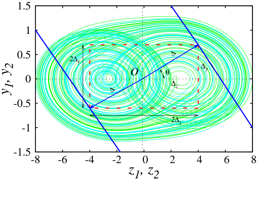
The central object is the oriented clipping window: a box in the response system's phase space, centered on the attractor and rotated by angle $\theta$ from a coordinate axis, with components $\Delta_x=\Delta\cos\theta$ and $\Delta_y=\Delta\sin\theta$. Coupling is active only while the response trajectory lies in that box ($\chi_A=1$), and inactive outside it. Stability is diagnosed with the master stability function $\lambda^\perp_{\max}$ and with the effectiveness $S(\theta)=\int_0^1 s(f,\theta)\,df$, where $s=1$ when $\lambda^\perp_{\max}<0$. Sweeping $\theta$ and the spatial clipping fraction $\Delta'=2\Delta/\Omega$ produces the reported optimal ranges.
What would settle it
Directly simulate the coupled Rössler equations with the switching term $\chi_A$ evaluated from the actual orbit's position in the oriented box, compute $\lambda^\perp_{\max}$ as a function of $\theta$ for $\varepsilon=10$, and compare the resulting $S(\theta)$ with the paper's spatial-scan $S(\theta)$; if the optimal windows shift, shrink, or disappear under the true temporal clipping fraction, the reported ranges are an artifact of that approximation.
Extended reading notes
Core claim
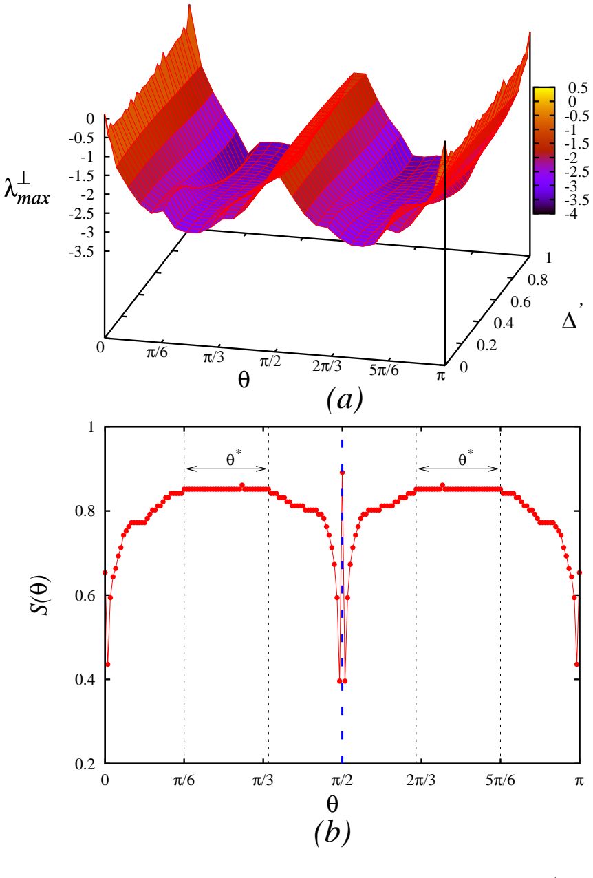
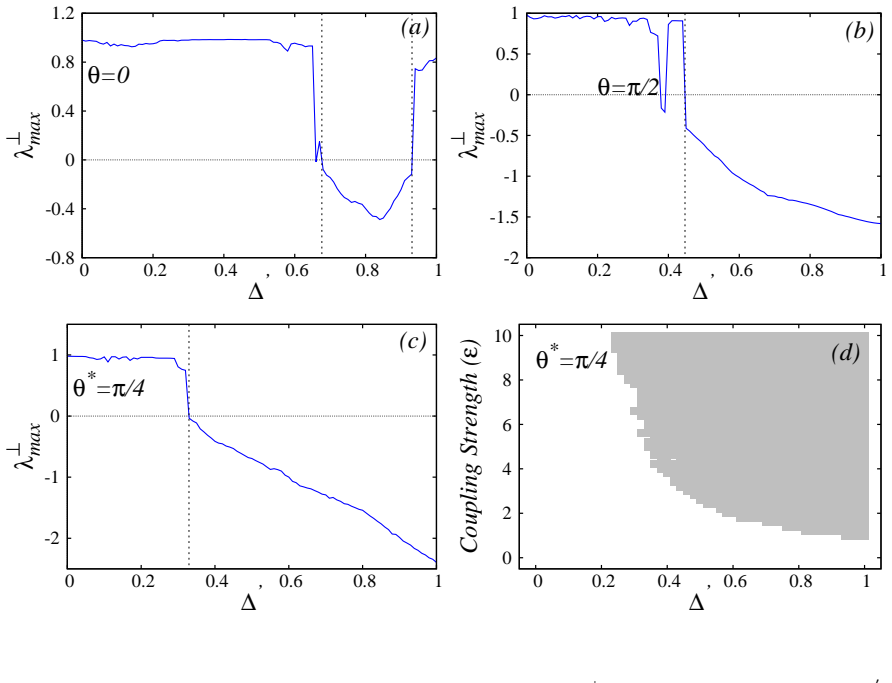
The central claim is that optimal uncoupling has preferred directions in phase space. For the Rössler system coupled through $x$ and $y$, clipping widths oriented at $0.1667\pi \le \theta^* \le 0.3444\pi$ and the mirror range $0.6556\pi \le \theta^* \le 0.8333\pi$ give stable synchronization with larger negative transverse Lyapunov exponents than clipping along either axis; for Chua's circuit coupled through $y$ and $z$, the ranges are $0.1667\pi \le \theta^* \le 0.3111\pi$ and $0.6889\pi \le \theta^* \le 0.8333\pi$. The effectiveness $S(\theta)=\int_0^1 s(f,\theta)\,df$ is symmetric about $\theta=\pi/2$, so the first quadrant suffices. Two-parameter diagrams in the $(\Delta', \varepsilon)$ plane at $\theta^*=\pi/4$ show connected negative-MSF regions, and phase portraits show drive and response synchronized inside the oriented clipped box.
Load-bearing premise
The paper's optimal angle ranges rest on the unproven assumption that the spatial fraction of the clipping box ($\Delta'$) equals the temporal fraction $f$ of the orbit that actually spends inside the box; for a chaotic attractor these need not match.
Editorial extensions
If this is right
- At fixed coupling strength, certain window orientations keep synchronization stable over a continuous band of clipping fractions, whereas axis-aligned clipping can fail at one end of that band.
- Because $S(\theta)$ is mirror-symmetric around $\theta=\pi/2$, future searches for optimal directions only need to scan half the orientation circle.
- The negative-MSF regions in the $(\Delta', \varepsilon)$ plane are connected, so synchronization remains stable as coupling strength is varied, not just at isolated parameter values.
- The optimal direction is a range rather than a single point, so the scheme tolerates small misalignment of the clipping window in practical implementations.
Reading between the lines
- A natural next test is whether the optimal tilt follows the attractor's dominant stretching directions; if so, the optimal range could be predicted from local Lyapunov-vector geometry instead of brute-force scanning.
- The symmetry about $\pi/2$ suggests a reflection-symmetry proof might exist for a broad class of symmetric couplings, which would reduce search cost in higher-dimensional systems.
- The reported method could be implemented electronically in Chua's circuit by switching a coupling resistor based on an oriented box mask; the paper does not test this hardware route.
Signed reviews
Editorial analysis
A structured set of objections, weighed in public.
Referee Report
Summary. The manuscript proposes an "optimal uncoupling" method for unidirectionally coupled chaotic systems, in which the phase-space region of the response system over which coupling is active is clipped by a window of width 2Δ with an orientation angle θ. For Rössler and Chua systems, the authors compute the master stability function λ⊥max as a function of θ and a clipping fraction Δ′, define an effectiveness measure S(θ), and report optimal orientation ranges (e.g., 0.1667π ≤ θ* ≤ 0.3444π for Rössler). Synchronization portraits and two-parameter stability diagrams in the Δ′–ε plane are presented to support the claim that orienting the clipping window enhances synchronization stability.
Significance. If the central claim were correct, the paper would introduce a practically useful control parameter—the orientation of the region over which transient uncoupling is active—and would extend the transient-uncoupling mechanism of Schröder et al. to directional control. The paper is clearly organized and applies the proposed method to two standard chaotic systems, with negative-MSF regions visible in the figures. These are genuine strengths. However, the numerical construction used in the paper does not implement an oriented clipping window; it implements an axis-aligned rectangle whose aspect ratio varies with θ. The reported "optimal directions" are therefore not about direction at all, and the main claim is not supported. The additional mismatch between the definition of S(θ) in terms of temporal clipping fraction and its evaluation using spatial clipping fraction, together with the absence of numerical details, further undermines the quantitative conclusions.
major comments (3)
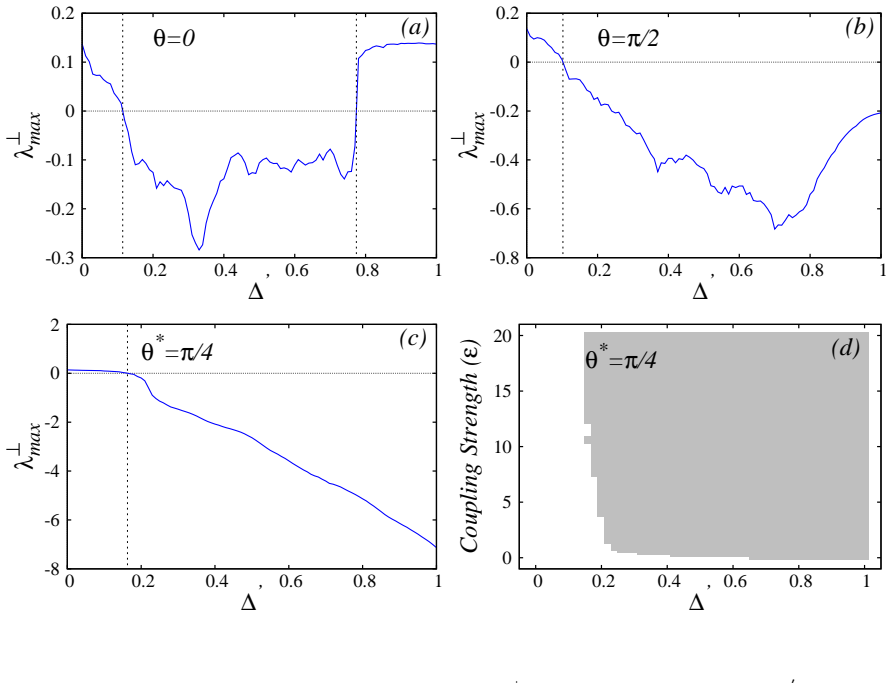
- [§III.A, Fig. 1, Eqs. (3)–(7)] The "oriented clipping window" is not a rotated window. In Section III.A the active region is described as the intersection of the components Δx = Δ cosθ and Δy = Δ sinθ, giving the box {|x2 − x*| ≤ Δ cosθ} ∩ {|y2 − y*| ≤ Δ sinθ}. This is an axis-aligned rectangle whose aspect ratio depends on θ, not a strip of width Δ normal to the direction n = (cosθ, sinθ). The two geometries coincide only at θ = 0 and θ = π/2, and at those values the rectangle degenerates to a line segment of zero area. Nevertheless, the text and Fig. 3(a) treat θ = 0 as ordinary x-coupling with a two-dimensional active region, which is internally inconsistent. Consequently, the ranges 0.1667π ≤ θ* ≤ 0.3444π and 0.6556π ≤ θ* ≤ 0.8333π reported in Fig. 2(b) are ranges of box aspect ratio, not of clipping orientation, and the central claim that orienting the clipping window enhances synchronization stability is not supported by the presented construction.
- [§III, work steps 2–4 and Eqs. (4)–(6)] The effectiveness metric S(θ) is defined in Eq. (4) as an integral over the temporal clipping fraction f, with f given in Eq. (6) as the long-time average of χA. However, in the work steps, S(θ) is evaluated by scanning the spatial clipping fraction Δ′ = 2Δx,y/Ωx,y. For a chaotic attractor, the fraction of time a trajectory spends inside a box is not generally equal to the box's spatial width fraction, and no such equivalence is proved or even argued. Moreover, Eq. (4) treats f as an integration variable even though f is a single number for a fixed clipping region; the relation between the integral over f and the scan over Δ′ is unexplained. The S(θ) curves used to identify θ* are therefore not justified by the stated definition, which is a second load-bearing problem for the quantitative claims.
- [§III.A and §III.B numerical results] No numerical details are provided for the computation of λ⊥max: there is no statement of the integration scheme or time step, the length of transients, the algorithm for transverse Lyapunov exponents, the grid resolution for the θ−Δ′ scans, or any convergence checks or error estimates. The quantitative thresholds (e.g., Δ′ ≥ 0.163 for θ* = π/4 in Fig. 3(c), the stable ranges in Figs. 3(a,b), and the analogous Chua system results in Fig. 7) cannot be reproduced or independently verified from the information given. Since the main results are numerical scans, this omission is a significant reproducibility issue.
minor comments (4)
- [§III.A, Fig. 3(a)] The text states the stable range for θ = 0 as 0.1145 ≤ Δ′ ≤ 0.7739, while the Fig. 3 caption states 0.1445; this discrepancy should be corrected.
- [Captions of Figs. 3, 4, and 7] There are typos: "dive" should be "drive" in Fig. 4, and "couping" should be "coupling" in Figs. 3 and 7.
- [References [1] and [16]] The author name "M. Pecora" should be "L. M. Pecora," and reference [1] is missing the full author list.
- [§III.A, Fig. 1] The choice of the attractor center O(x*, y*) used to define the clipping box is a free parameter; the sensitivity of the reported optimal ranges to this choice is not discussed.
Circularity Check
No circularity: the optimal orientation ranges are direct MSF-scan outputs, not restatements of fitted inputs.
full rationale
The paper's central claim is a numerical result: the optimal clipping-orientation ranges are obtained by scanning the master stability function over θ and clipping fraction, with no parameter fitted to the claimed optimum. S(θ) is defined in Eq. (4) from the synchrony indicator and then evaluated in Section III steps 2–4 over the spatial clipping fraction Δ'; this temporal-versus-spatial mismatch is a consistency concern, not a circular reduction, because the reported θ* ranges are not set equal to any input by construction. The only self-citation, [21], appears in the introduction as background on attractor-size effects and is not load-bearing for the MSF calculation or the orientation scan. The Rössler and Chua results are produced in-model from the stated coupled equations, and the synchronization portraits provide an internal check rather than a circular validation. The geometry objection—that Fig. 1 depicts an axis-aligned rectangle with θ-dependent aspect ratio rather than a genuinely rotated clipping strip—concerns whether the computed quantity matches the claimed interpretation, which is a correctness/interpretation issue outside the circularity definition. Therefore no circular step can be exhibited, and the appropriate finding is no significant circularity.
Assumptions & free parameters
free parameters (1)
- Attractor center O(x*, y*) for clipping reference =
Rössler: (1.2, -1.5); Chua: (-0.116, -0.002)
assumptions (5)
- domain assumption The largest transverse Lyapunov exponent λ⊥max < 0 is a valid criterion for synchronization stability.
- ad hoc to paper The temporal clipping fraction f may be replaced by the spatial clipping fraction Δ' when evaluating S(θ).
- ad hoc to paper An oriented clipping window is equivalent to independent thresholds on two coordinate variables, forming a 2Δx × 2Δy box.
- domain assumption For the Rössler system, deviation along the z-axis can be neglected, so the x-y plane suffices.
- domain assumption Drive and response systems are identical and unidirectionally coupled, so the synchronization manifold is invariant.
Cite this review
Pith. "Pith review of Effect of optimal uncoupling in enhancing synchronization stability in coupled chaotic systems." pith.science (2026). https://pith.science/paper/P2E2FQBK
@misc{pith2026190809490,
  author       = {Pith},
  title        = {Pith review of: Effect of optimal uncoupling in enhancing synchronization stability in coupled chaotic systems},
  year         = {2026},
  howpublished = {\url{https://pith.science/paper/P2E2FQBK}},
  note         = {Machine review of arXiv:1908.09490}
}
read the original abstract
In this paper, we report a novel approach for studying the effect of optimal uncoupling on the stability of synchronization in coupled chaotic systems. The clipping of phase space of the driven system having an orientation along the coordinate axes revealing the nature of coupling of the state variables of coupled systems is identified in certain coupled third-order chaotic systems. The stability of synchronization is studied through the {\emph{Master Stability Function}} (MSF). The optimal directions of implementing the clipping width to achieve stable synchronization is observed by studying the effectiveness of clipping fraction and the sufficient range of orientation to identify the optimal directions is reported. The functional work steps for identifying the optimal directions are presented and the synchronization of the response system with the drive within the clipped region of phase space for different orientations of clipping width are studied. The stability of synchronization for different orientations of clipping widths and the two-parameter bifurcation diagram indicating the negative valued MSF regions obtained for the optimal direction of clipping width are presented. The application of the method of optimal uncoupling in identifying the direction of implication of clipping width is discussed and the range of orientation over which the clipping width has to be varied is generalized.
Figures

Figures from the paper (5 more)



Reference graph
Works this paper leans on
-
[1]
Fix the center of the chaotic attractor of the response syste m ( x∗ 2, y∗
-
[2]
along the co- ordinate axis of the state variable coupled to the drive system
-
[3]
For a fixed value of θ and clipping width ∆ identify the region of phase space within 6 which the coupling strength is active by resolving the horizontal (∆ x = ∆ cosθ) and vertical component (∆ y = ∆ sinθ) of the vector OA (OA = ∆) and estimate λ⊥ max
-
[4]
Vary the clipping fraction ∆ ′ (∆ ′ x = 2∆ x/Ω x, ∆ ′ y = 2∆ y/Ω y) in the range 0 ≤ ∆ ′ ≤ 1 in steps, identify the active phase-phase region of coupling streng th to estimate λ⊥ max in each step and evaluate the effectiveness of clipping fraction S(θ) using the synchrony indicator s(θ) obtained for each step of clipping fraction
-
[5]
Evaluate S(θ) for each value of θ by varying θ in steps in the range 0 ≤ θ ≤ π by repeating steps 2 and 3
-
[6]
Plot S(θ) obtained for the corresponding value of θ to find the optimal directions θ∗. The stability of synchronization of the coupled R¨ osslersystems can be analyzed by observing the MSF to identify the optimal direction of implementing th e clipping width with respect to a particular coordinate axis. Fig. 2(a) shows the variat ion of MSF as functions of...
-
[7]
M. Pecora, T. L. Carroll, Synchronization in chaotic sys tems, Physical Review Letters 64 (1990) 821–824. doi:10.1103/PhysRevLett.64.821
-
[8]
A. Pikovsky, M. Rosenblum, J. Kurths, J. Kurths, Synchro nization: A Universal Concept in Nonlinear Sciences, Cambridge Nonlinear Science Series, C ambridge University Press, 2003
work page 2003
Show all 32 references
-
[9]
N. F. Rulkov, A. R. Volkoskii, A. Rodri ´ ıguez-Lozano, E. Del R ´ ıo, M. G. Ve- larde, Mutual synchronization of chaotic self-oscillator s with dissipative coupling, International Journal of Bifurcation and Chaos 02 (03) (199 2) 669–676. arXiv:https://doi.org/10.1142/S0218127...
-
[10]
doi:10.1142/S0218127492000811
Leon.O.Chua, Ljupco Kocarev, Kevin Eckert, Makoto Itoh , Experimental chaos synchroniza- tion in chua’s circuit, International Journal of Bifurcati on and Chaos 2 (3) (1992) 705–708. doi:10.1142/S0218127492000811
1992 doi
-
[11]
10 doi:10.1142/S0218126693000071
Leon.O.Chua, Ljupco Kocarev, Kevin Eckert, Makoto Itoh , Chaos synchronization in chua’s circuit, International Journal of Circuits, Systems and Co mputers 3 (1) (1993) 93–108. 10 doi:10.1142/S0218126693000071
1993 doi
-
[12]
doi:10.1103/PhysRevE.48.R1624
K.Murali, M.Lakshmanan, Transmission of signals by syn chronization in a chaotic van der pol- duffing oscillator, Physical Review E 48 (1993) 1624–1626. doi:10.1103/PhysRevE.48.R1624
1993 doi
-
[13]
S.Zhou, The synchronization of chaotic systems, Physics Reports 366 (2002) 1–101
S.Boccaletti, J.Kurths, G.Osipov, D.L.Valladares, C. S.Zhou, The synchronization of chaotic systems, Physics Reports 366 (2002) 1–101. doi:10.1016/S0370-1573(02)00137-0
2002 doi
-
[14]
M. Chen, M. Sun, H. Bao, Y. Hu, B. Bao, Fluxcharge analysis of two-memristor-based Chua’s circuit: Dimensionality decreasing model for detecting ex treme multistability, IEEE Transac- tions on Industrial Electronics 67 (3) (2020) 2197–2206. doi:10.1109/TIE.2019.2907444
2020
-
[15]
A. V. Oppenheim, G. W. Wornell, S. H. Isabelle, K. M. Cuomo , Signal processing in the context of chaotic signals, in: [Proceedings] ICASSP-9 2: 1992 IEEE International Conference on Acoustics, Speech, and Signal Processing, Vo l. 4, 1992, pp. 117–120. doi:10.1109/ICASSP.1992.226472
1992
-
[16]
doi:10.1103/PhysRevE.49.4882
K.Murali, M.Lakshmanan, Drive-response scenario of c haos synchronization in identical non- linear systems, Physical Review E 49 (1994) 4882–4885. doi:10.1103/PhysRevE.49.4882
1994 doi
-
[17]
Murali, M
K. Murali, M. Lakshmanan, Efficient signal transmission by synchronization through compound chaotic signal, Phys. Rev. E 56 (1997) 251–255. doi:10.1103/PhysRevE.56.251. URL https://link.aps.org/doi/10.1103/PhysRevE.56.251
1997 doi
-
[18]
A. A. Koronovskii, O. I. Moskalenko, A. E. Hramov, On the use of chaotic synchronization for secure communicat ion, Physics-Uspekhi 52 (2009) 1213 – 1238. doi:https://doi.org/10.3367/ufne.0179.200912c.1281. URL https://doi.org/10.3367%2Fufne.0179.200912c.1281
2009
-
[19]
Z. Wu, X. Zhang, X. Zhong, Generalized chaos synchroniz ation circuit sim- ulation and asymmetric image encryption, IEEE Access 7 (201 9) 37989–38008. doi:10.1109/ACCESS.2019.2906770
2019
-
[20]
J. Wang, W. Yu, J. Wang, Y. Zhao, J. Zhang, D. Jiang, A new six-dimensional hyperchaotic system and its secure co mmunication circuit implementation, International Journal of Circuit Theory and Applications 4 7 (5) 702–
-
[21]
Sivaganesh, A
G. Sivaganesh, A. Arulgnanam, A.N. Seethalakshmi, Sta bility enhancement by induced synchronization using trans ient uncoupling in certain coupled chaotic systems, Chaos, Solitons & Fractals 123 (2019) 217 – 228. doi:https://doi.org/10.1016/j.chaos.2019.04.009. URL http://www....
2019 doi
-
[22]
N. Wang, C. Li, H. Bao, M. Chen, B. Bao, Generating multi- scroll Chua’s attractors via sim- 11 plified piecewise-linear Chua’s diode, IEEE Transactions o n Circuits and Systems I: Regular Papers 66 (12) (2019) 4767–4779. doi:10.1109/TCSI.2019.2933365
2019
-
[23]
Pecora, T
M. Pecora, T. L. Carroll, Master stability functions fo r synchronized coupled systems, Physical Review Letters 80 (1998) 2109–2112. doi:10.1103/PhysRevLett.80.2109
1998 doi
-
[24]
Schr¨ oder, M
M. Schr¨ oder, M. Mannattil, D. Dutta, S. Chakraborty, M . Timme, Transient uncoupling induces synchronization, Phys. Rev. Lett. 115 (2015) 054101. doi:10.1103/PhysRevLett.115.054101. URL https://link.aps.org/doi/10.1103/PhysRevLett.115.054101
2015 doi
-
[25]
Schr¨ oder, S
M. Schr¨ oder, S. Chakraborty, D. Witthaut, J. Nagler, M . Timme, Interaction con- trol to synchronize non-synchronizable networks, Scienti fic Reports 6 (2016) 37142. doi:10.1038/srep37142
2016 doi
-
[26]
Tandon, M
A. Tandon, M. Schr¨ oder, M. Mannattil, M. Timme, S. Chak raborty, Synchronizing noisy nonidentical oscillators by transien t uncoupling, Chaos: An Interdisciplinary Journal of Nonlinear Science 26 (9) (2 016) 094817. arXiv:https://doi.org/10.1063/1.4959141, doi:10.1063/1.4959...
-
[27]
Ghosh, P
A. Ghosh, P. Godara, S. Chakraborty, Understanding tra nsient uncoupling induced synchronization through modifie d dynamic coupling, Chaos: An Interdisciplinary Journal of Nonlinear Science 2 8 (5) (2018) 053112. arXiv:https://doi.org/10.1063/1.5016148, doi:10.1063/1.5016148. U...
2018 doi
-
[29]
Pecora, T
M. Pecora, T. L. Carroll, A. Johnson, J. Mar, J. F. Heagy, Fundamentals of synchronization in chaotic systems, concepts, and applications, Chaos 7 (1997 ) 520–543. doi:10.1063/1.166278
1997 doi
-
[30]
R¨ ossler, An equation for continuous chaos, Physics Letters A 57 (5) (1976) 397 – 398
O. R¨ ossler, An equation for continuous chaos, Physics Letters A 57 (5) (1976) 397 – 398. doi:https://doi.org/10.1016/0375-9601(76)90101-8
1976 doi
-
[31]
Matsumoto, A chaotic attractor from chua’s circuit, IEEE Transactions on Circuits and Systems 31 (12) (1984) 1055–1058
T. Matsumoto, A chaotic attractor from chua’s circuit, IEEE Transactions on Circuits and Systems 31 (12) (1984) 1055–1058. doi:10.1109/TCS.1984.1085459
1984
-
[32]
Matsumoto, L
T. Matsumoto, L. O. Chua, M. Komuro, The double scroll, I EEE Transactions on Circuits and Systems 32 (8) (1985) 797–818. doi:10.1109/TCS.1985.1085791. 12 -12 -8 -4 0 4 8 -10 -5 0 5 10 y1, y2 x1, x2 2∆ x 2∆ y θ ∆ ∆ ∆ x ∆ y O FIG. 1: (Color Online) R¨ osslersystem: Clipping of ...
1985
-
[717]
URL https://onlinelibrary.wiley.com/doi/abs/10.1002/cta.2617
arXiv:https://onlinelibrary.wiley.com/doi/pdf/10.1002/cta.2617, doi:10.1002/cta.2617. URL https://onlinelibrary.wiley.com/doi/abs/10.1002/cta.2617
Reviewed August 14, 2026 · model on record in the stance chip above.
Discussion (0). Continue with ORCID to comment.