REVIEW 3 major objections 5 minor 22 references
Continuous Toolpath Planning in Additive Manufacturing
T0 review · 3 major / 5 minor · reviewed 2026-08-14 · deepseek-v4-flash
Pith's one-line read Each layer's infill becomes one continuous, non-self-crossing print path.
desk verdict A credible pipeline for continuous infill toolpaths whose abstract overclaims a guarantee the paper's own remarks qualify away; worth refereeing, but the claims need real tightening. read the letter →
The pith
A machine-rendered reading of the paper's core claim, the machinery that carries it, and where it could break.
The reading
What carries the argument
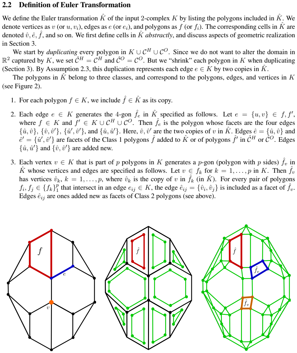
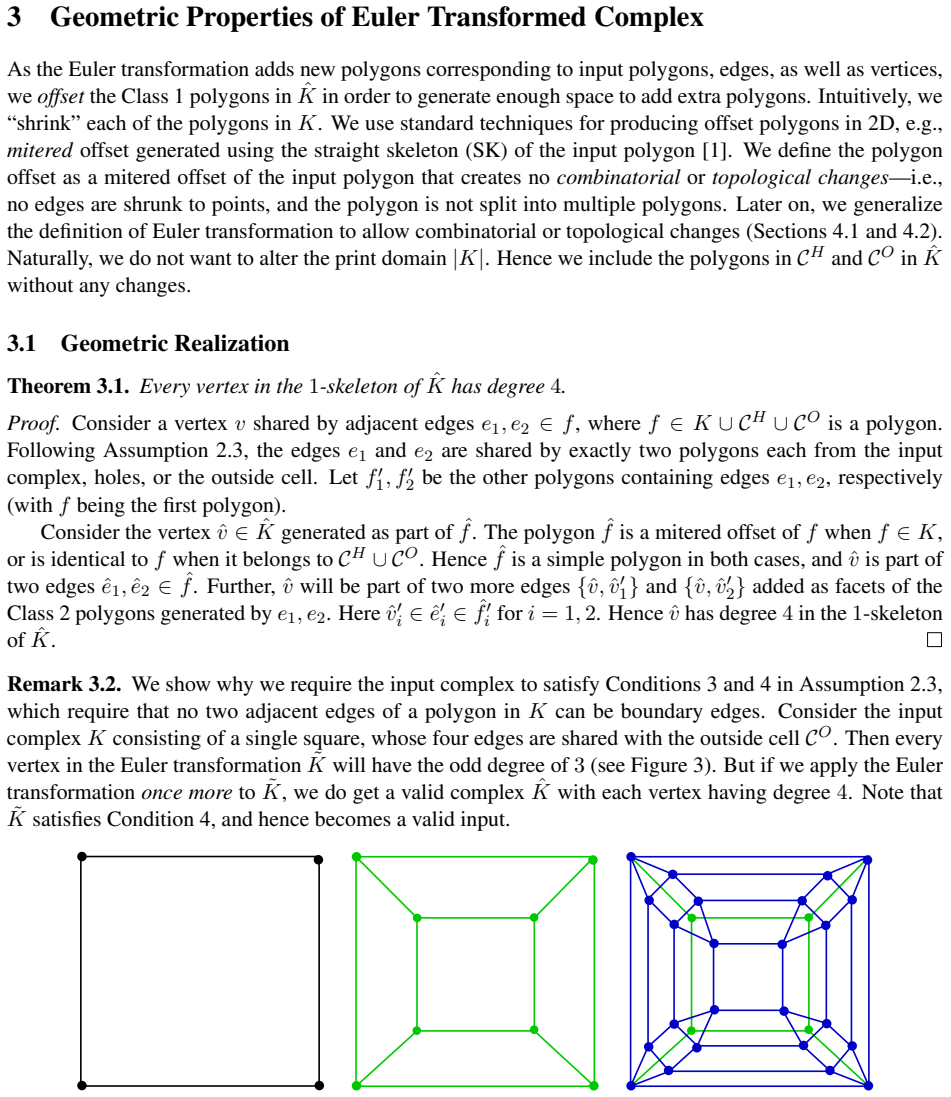
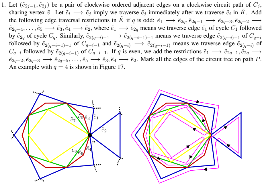
The load-bearing construction is the Euler transformation of a 2D cell complex: shrink each polygon by a mitered offset, add a quadrilateral for each edge, and add a polygon for each vertex, which makes the 1-skeleton's every vertex have even degree (degree 4 under the paper's boundary assumptions). The second mechanism is clip-and-patch: clipping the transformed complex to a layer polygon creates an even number of odd-degree vertices, and the patch operation joins alternate odd vertices along the layer boundary, adding new polygons to keep the complex pure and connected. The third mechanism is the circuit tree: a modified circuit-search algorithm decomposes the Eulerian 1-skeleton into edge-disjoint concentric circuits, and traversal rules alternate the orientation between parent and child circuits, with explicit edge transitions at shared vertices, to avoid subpath crossovers both within and between circuits. These constructions, together with support edges printed in place of omitted boundary segments, carry the paper's guarantee.
What would settle it
Slice a model so that at some layer the clipped complex $\widetilde{K}$ contains a component that is a simple path with no cycles, and run the full pipeline. Lemma 5.3 explicitly excludes this case, so if the patch step still outputs a connected Eulerian complex and the traversal prints every edge with zero travel moves, the guarantee extends further than the proof; if it inserts a travel move or duplicates an edge, the guarantee fails as stated. A second concrete check: choose a layer polygon so narrow that a boundary cell in $\widetilde{K}$ has width below the extruder diameter $2r$; the paper states such cells can be unshrinkable, so a printed path that skips edges or must travel confirms the open-problem boundary of the claim.
Extended reading notes
Core claim
This paper's central claim is that continuous toolpath planning in sparse-infill 3D printing can be reduced to keeping a per-layer cell complex Eulerian. Given a pure 2-complex $K$ meshing the union of all layer polygons, the authors define the Euler transformation $\widehat{K}$: each polygon of $K$ is replaced by an inward mitered offset, each edge by a quadrilateral, and each vertex by a $p$-gon, so that every vertex in the 1-skeleton $\widehat{G}$ has degree 4. Slicing then clips $\widehat{K}$ by the layer polygon; clipping can create an even number of odd-degree vertices on the boundary, and the patch step pairs alternating odd vertices by paths along the layer boundary, restoring even degrees and connectivity as long as no clipped component is a simple path. The result is a connected pure 2-complex $\widetilde{K}$ whose 1-skeleton is Eulerian, so an Eulerian tour exists that prints every edge exactly once. To make the tour physically printable, the paper decomposes $\widetilde{K}$ into concentric circuits and specifies edge transitions so that parent and child circuits are traversed in opposite orientations, which eliminates crossovers. The conclusion is a guarantee, within the stated assumptions, of one continuous non-self-crossing tool path for every connected piece of every layer, with support edges printed for any segments that would otherwise have no material underneath.
Load-bearing premise
The single-pass guarantee holds only if every clipped-and-patched boundary cell can be shrunk by the extruder radius without splitting or disappearing, and no clipped piece is a bare simple path; the paper explicitly leaves those cases open.
Editorial extensions
If this is right
- Every connected piece of every layer is claimed to be printable in one continuous extrusion, eliminating nozzle stops and starts and the teardrop-like defects they leave behind.
- The tool path never repeats an edge and never crosses itself at vertices, provided the layer's clipped complex contains no unshrinkable cells or simple-path components.
- Support edges printed in place of skipped boundary segments keep all next-layer edges supported, so for epsilon-continuous layers the print does not occur in free space.
- The per-layer mesh size stays within small constant multiples of the input mesh (four times the edges, for instance), and the path search runs in $O(|E|^2)$, so dense infill remains feasible.
- The method works for layers with holes, multiple components, and nonconvex geometry; a benchmark object with many intermediate layers split into disjoint polygons is used to demonstrate the same pipeline throughout.
Reading between the lines
- Going beyond the paper: when a clipped component is a simple path or a boundary cell is unshrinkable—both explicitly left open—a natural repair is to split that component into two continuous subpaths and join them by a short travel move; the framework would then minimize the number of interruptions rather than guarantee zero.
- Going beyond the paper: the same Euler-transformation pipeline could serve as a general coverage planner for any single-pass extrusion or sweeping process, such as robotic floor coverage or CNC pocket clearing, by reinterpreting the "support below" condition as a machine or environmental constraint.
- Going beyond the paper: the guarantee is graph-theoretic; a practical pre-print check would compute the minimum clearance between nonadjacent infill edges in each layer and compare it with the extruder diameter, since collisions arise exactly where that clearance drops below $2r$.
- Going beyond the paper: one could quantify the improvement empirically by counting nozzle lifts and travel moves on benchmark objects; the paper's design predicts zero infill travel moves except where support perimeters are intentionally added.
Signed reviews
Editorial analysis
A structured set of objections, weighed in public.
Referee Report
Summary. The paper proposes a computational framework for continuous toolpath planning in sparse-infill 3D printing. The pipeline takes a mesh of the union of all layer polygons, applies the authors' Euler transformation to obtain a 2-complex whose 1-skeleton is Eulerian, clips and patches this complex per layer to restore even degrees, adds support perimeters to avoid unsupported edges, and finally uses a circuit-tree traversal to produce a single non-crossing continuous path per connected component. The authors claim this guarantee holds 'irrespective of complex geometry or topology' and report implementations on a pyramid, a star, and the Stanford bunny.
Significance. If the stated guarantee were fully established, this would be a valuable contribution to additive manufacturing toolpath planning: it avoids retraction moves, repeated-edge deposition, and path crossovers, and it is built on a parameter-free combinatorial construction with linear cell growth (Lemma 3.3), planarity (Lemma 3.5), and a working implementation on nontrivial geometry. The Euler transformation itself is a clean and reusable idea, and the paper's attention to support and overhang issues goes beyond purely graph-theoretic treatments. However, the advertised per-layer guarantee is not actually established for all layers: the paper's own Remarks 5.5 and 7.2 concede that continuous printing of boundary edges is unresolved when clipped and patched boundary polygons are unshrinkable or shrinkable with topological changes, and Section 7 turns the affected edges into travel paths. The contribution remains promising, but the central claim must be narrowed or augmented with verifiable conditions.
major comments (3)
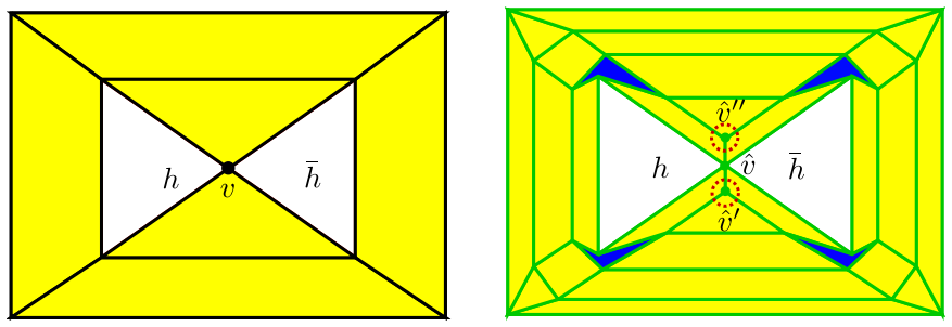
- [Abstract; §1.1; §5.3 Step 5; §7, Remarks 5.5 and 7.2] The abstract's guarantee of a single continuous tool path covering every connected piece of every layer, 'irrespective of complex geometry or topology', is contradicted by the paper itself. Remark 5.5 states that boundary polygons in the clipped and patched complex can be shrinkable with topological changes or unshrinkable, and Remark 7.2 states that it is still an open problem how to continuously print boundary edges in these cases. In Section 7 (Case 1 and Case 2), the affected boundary edges are set as travel paths rather than deposit paths, so the resulting plan does not provide a single continuous extrusion covering all edges of that layer. Please either prove these exceptional polygons cannot arise under the assumptions of Section 5.3, add an explicit condition excluding them together with a verification procedure, or revise the abstract and contributions to state the guarantee only for layers whose clipped and patched complex has no such boundary 2-cells.
- [Lemma 5.3; §5.3 Step 5] Lemma 5.3 is proved only under the assumption that no component produced by the Clip step is a simple path. This assumption is not part of Assumption 2.3, nor is it established by Step 4's extruder-size assumption, which concerns the pre-clip complex \hat K. Step 5 nonetheless invokes Lemma 5.3 to conclude that \tilde K is connected and Eulerian. Thus the framework does not currently prove its per-layer guarantee for all valid inputs; either a proof that simple-path components cannot occur, or an explicit assumption ruling them out, must be added.
- [§5.3 Step 6; Remark 5.4] The framework claims to prevent printing in free space by adding a support perimeter for non-printed boundary paths, but Remark 5.4 says that coverage of the non-printed path \tilde P by the added support circles is not guaranteed, since coverage depends on the curvature of \tilde P. This directly affects the physical validity of the generated toolpath and the ``no printing in free space'' goal stated in Section 1.1. Please specify conditions under which the support construction covers \tilde P, or revise the claim to reflect that support coverage is conditional.
minor comments (5)
- [Abstract] The sentence 'We implement our test our framework on several 3D objects' contains a typo and should read 'We implement and test our framework on several 3D objects.'
- [§1.1] The parenthetical phrase 'see Section 7 for an exception arising in certain cases with extreme geometries' already concedes a limitation contradicting the stronger guarantee in the abstract; this sentence should be aligned with the revised claim after the major comments are addressed.
- [Definition 5.2] The description of joining alternate pairs of vertices in S is difficult to follow: please clarify the indexing of the clockwise sequence, what 'edge {v1, v2} is not included' refers to, and how the two possible pairing choices are to be selected in general.
- [§6.2] The traversal restrictions define edges e_1, ..., e_2q at a shared vertex but do not specify a precise local ordering convention for these edge indices; please define the indexing relative to the clockwise order of the incident edges.
- [§8] The pyramid dimensions are reported as 609.6 mm in Section 8 but as 610 mm in the Figure 1 caption; please reconcile these values.
Circularity Check
No circularity: the Eulerian construction is self-contained; the paper's own remarks limit the scope of the guarantee but do not reveal a derivation equivalent to its inputs.
full rationale
The load-bearing construction is derived in the paper rather than imported as a fitted or cited result. The Euler transformation is defined in Section 2.2 and its key properties are proved here (Theorem 3.1 degree 4, Lemma 3.5 planarity, Proposition 3.7 connectivity, Lemma 3.3 cell counts) under Assumption 2.3. Citations to the authors' prior [12] appear only for peripheral estimates (Remark 3.4) and geometric-quality parameters (Section 7), so they are not load-bearing. The clipping and patching step converts the sliced complex into an Eulerian complex by explicitly adding edges to pair odd-degree vertices, and Lemma 5.3 proves the Eulerian and connected conclusions from the handshake lemma, with the simple-path case excluded; this is a constructive derivation, not a prediction fitted to data. The mitered offset and overhang coefficient c are user-chosen inputs, not fitted constants. The genuine weakness is an admitted completeness gap, not circularity: Remark 5.5 says boundary polygons from clip/patch 'can be shrinkable with topological changes or unshrinkable,' and Remark 7.2 says continuous printing of such boundary edges 'is still an open problem'; Lemma 5.3 also excludes simple-path components. These admissions mean the abstract's unconditional 'every layer' guarantee is overbroad as stated, but they do not make the derivation reduce to its own inputs.
Assumptions & free parameters
free parameters (2)
- mitered offset distance =
1 mm for Stanford bunny; user-chosen
- overhang coefficient c =
0 <= c <= 1, user-chosen
assumptions (5)
- domain assumption Input 2-complex K together with holes CH and outside CO satisfies the intersection conditions of Assumption 2.3.
- domain assumption Consecutive sliced layers are epsilon-continuous.
- ad hoc to paper No component produced by the Clip step is a simple path.
- ad hoc to paper Boundary polygons in the patched complex are shrinkable with no topological changes.
- domain assumption Extruder size does not cause edge covering or material collision in the transformed complex.
Cite this review
Pith. "Pith review of Continuous Toolpath Planning in Additive Manufacturing." pith.science (2026). https://pith.science/paper/PHFS6S2V
@misc{pith2026190807452,
  author       = {Pith},
  title        = {Pith review of: Continuous Toolpath Planning in Additive Manufacturing},
  year         = {2026},
  howpublished = {\url{https://pith.science/paper/PHFS6S2V}},
  note         = {Machine review of arXiv:1908.07452}
}
read the original abstract
We develop a framework that creates a new polygonal mesh representation of the sparse infill domain of a layer-by-layer 3D printing job. We guarantee the existence of a single, continuous tool path covering each connected piece of the domain in every layer. We present a tool path algorithm that traverses each such continuous tool path with no crossovers. The key construction at the heart of our framework is an Euler transformation which converts a 2-dimensional cell complex K into a new 2-complex K^ such that every vertex in the 1-skeleton G^ of K^ has even degree. Hence G^ is Eulerian, and a Eulerian tour can be followed to print all edges in a continuous fashion. We start with a mesh K of the union of polygons obtained by projecting all layers to the plane. We compute its Euler transformation K^. In the slicing step, we clip K^ at each layer using its polygon to obtain a complex that may not necessarily be Euler. We then patch this complex by adding edges such that any odd-degree nodes created by slicing are transformed to have even degrees again. We print extra support edges in place of any segments left out to ensure there are no edges without support in the next layer. These support edges maintain the Euler nature of the complex. Finally we describe a tree-based search algorithm that builds the continuous tool path by traversing "concentric" cycles in the Euler complex. Our algorithm produces a tool path that avoids material collisions and crossovers, and can be printed in a continuous fashion irrespective of complex geometry or topology of the domain (e.g., holes). We implement our test our framework on several 3D objects. Apart from standard geometric shapes, we demonstrate the framework on the Stanford bunny.
Figures

Figures from the paper (19 more)




Reference graph
Works this paper leans on
-
[1]
A novel type of skeleton for polygons
Oswin Aichholzer, Franz Aurenhammer, David Alberts, and Bernd G ¨artner. A novel type of skeleton for polygons. Journal of Universal Computer Science, 1(12):752–761, 1995
work page 1995
-
[2]
Three-dimensional straight skeletons from bisector graphs
Franz Aurenhammer and Gernot Walzl. Three-dimensional straight skeletons from bisector graphs. In Proceedings of 5th International Conference Analytical Number Theory and Spatial Tessellations , pages 15–29, 2013
work page 2013
-
[3]
Straight skeletons and mitered offsets of nonconvex polytopes
Franz Aurenhammer and Gernot Walzl. Straight skeletons and mitered offsets of nonconvex polytopes. Discrete and Computational Geometry, 56(3):743–801, 2016
work page 2016
-
[4]
F. T. Boesch, C. Suffel, and R. Tindell. The spanning subgraphs of Eulerian graphs. Journal of Graph Theory, 1(1):79–84, 1977
work page 1977
-
[5]
Parameterized complexity of even/odd subgraph problems
Leizhen Cai and Boting Yang. Parameterized complexity of even/odd subgraph problems. Journal of Discrete Algorithms, 9(3):231–240, 2011
work page 2011
-
[6]
Zuo Llang Cao, Yuyu Huang, and Ernest L. Hall. Region filling operations with random obstacle avoidance for mobile robots. Journal of Robotic Systems, 5(2):87–102, 1988. 29
work page 1988
-
[7]
E. Catmull and J. Clark. Recursively generated b-spline surfaces on arbitrary topological meshes. Computer-Aided Design, 10(6):350 – 355, 1978
work page 1978
-
[8]
Donghong Ding, Zengxi Pan, Dominic Cuiuri, and Huijun Li. A practical path planning methodology for wire and arc additive manufacturing of thin-walled structures. Robotics and Computer-Integrated Manufacturing, 34:8–19, 2015
work page 2015
Show all 22 references
-
[9]
Doo and M
D. Doo and M. Sabin. Behaviour of recursive division surfaces near extraordinary points. Computer- Aided Design, 10(6):356 – 360, 1978
1978
-
[10]
Path optimization along lattices in additive manufacturing using the Chinese postman problem.3D Printing and Additive Manufacturing, 4(2):98– 104, 2017
Gregory Dreifus, Kyle Goodrick, Scott Giles, Milan Patel, Reed Foster, Cody Williams, John Lindahl, Brian Post, Alex Roschli, Lonnie Love, and Vlastimil Kunc. Path optimization along lattices in additive manufacturing using the Chinese postman problem.3D Printing and Additive ...
2017
-
[11]
A survey on coverage path planning for robotics
Enric Galceran and Marc Carreras. A survey on coverage path planning for robotics. Robotics and Autonomous Systems, 61(12):1258–1276, 2013
2013
-
[12]
Euler transformation of polyhedral complexes
Prashant Gupta and Bala Krishnamoorthy. Euler transformation of polyhedral complexes. CoRR, abs/1812.02412, 2018. arXiv:1812.02412
2018 arXiv
-
[13]
Algebraic Topology
Allen Hatcher. Algebraic Topology. Cambridge University Press, Cambridge, 2002
2002
-
[14]
Ueber die M ¨oglichkeit, einen Linienzug ohne Wiederholung und ohne Unterbrechung zu umfahren
Carl Hierholzer and Chr Wiener. Ueber die M ¨oglichkeit, einen Linienzug ohne Wiederholung und ohne Unterbrechung zu umfahren. Mathematische Annalen, 6(1):30–32, Mar 1873
-
[15]
A novel path planning methodology for extrusion-based additive manufacturing of thin-walled parts
Yuan Jin, Yong He, and Jianke Du. A novel path planning methodology for extrusion-based additive manufacturing of thin-walled parts. International Journal of Computer Integrated Manufacturing , 30(12):1301–1315, 2017
2017
-
[16]
A non-retraction path planning ap- proach for extrusion-based additive manufacturing.Robotics and Computer-Integrated Manufacturing, 48:132–144, 2017
Yuan Jin, Yong He, Guoqiang Fu, Aibing Zhang, and Jianke Du. A non-retraction path planning ap- proach for extrusion-based additive manufacturing.Robotics and Computer-Integrated Manufacturing, 48:132–144, 2017
2017
-
[17]
Tim Kuipers, Jun Wu, and Charlie C.L. Wang. CrossFill: Foam structures with graded density for continuous material extrusion. Computer-Aided Design, 114:37–50, 2019. arXiv:1906.03027
2019 arXiv
-
[18]
James R. Munkres. Elements of Algebraic Topology. Addison–Wesley Publishing Company, Menlo Park, 1984
1984
-
[19]
Infill optimization for additive manu- facturingapproaching bone-like porous structures
Jun Wu, Niels Aage, R ¨udiger Westermann, and Ole Sigmund. Infill optimization for additive manu- facturingapproaching bone-like porous structures. IEEE Transactions on Visualization and Computer Graphics, 24(2):1127–1140, Feb 2018
2018
-
[20]
Jun Wu, Charlie C. L. Wang, Xiaoting Zhang, and R ¨udiger Westermann. Self-supporting rhombic infill structures for additive manufacturing. Computer-Aided Design, 80:32–42, 2016
2016
-
[21]
Graph Planning for Environmental Coverage
Ling Xu. Graph Planning for Environmental Coverage . PhD thesis, Carnegie Mellon University, Pittsburgh, PA, August 2011
2011
-
[22]
Connected Fermat spirals for layered fabrication
Haisen Zhao, Fanglin Gu, Qi-Xing Huang, Jorge Garcia, Yong Chen, Changhe Tu, Bedrich Benes, Hao Zhang, Daniel Cohen-Or, and Baoquan Chen. Connected Fermat spirals for layered fabrication. ACM Transactions on Graphics, 35(4):100:1–100:10, July 2016. 30
2016
Reviewed August 14, 2026 · model on record in the stance chip above.
Discussion (0). Continue with ORCID to comment.