The Influence of Gain and Phase Mismatches on Beam Patterns in Phased Arrays
Pith reviewed 2026-06-27 05:44 UTC · model grok-4.3
The pith
Gain and phase mismatches produce weighted replicas of the ideal beampattern whose amplitudes are given by the discrete Fourier transform of the mismatch sequence.
A machine-rendered reading of the paper's core claim, the machinery that carries it, and where it could break.
Core claim
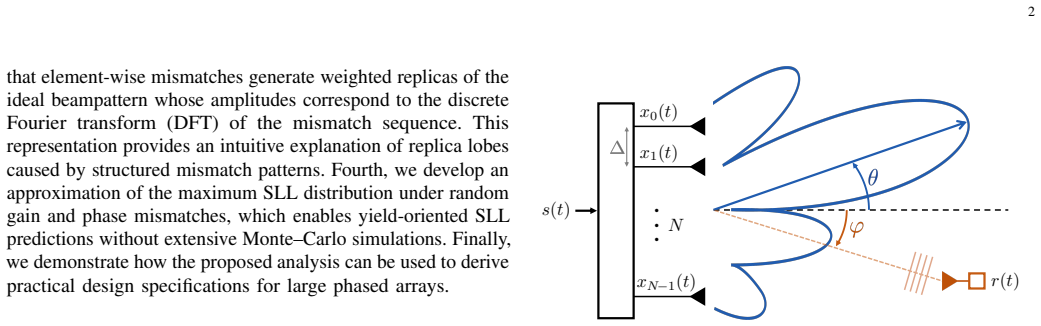
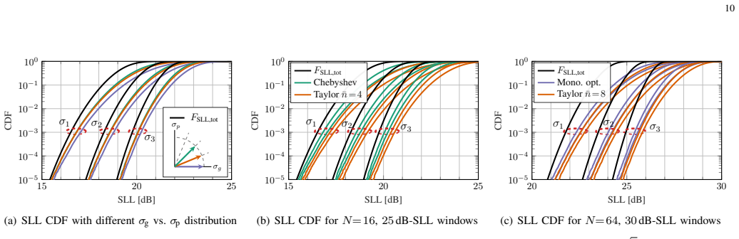
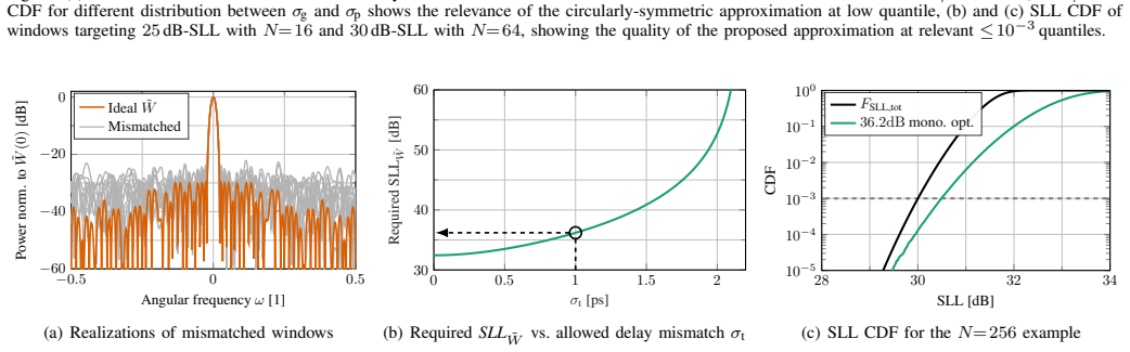
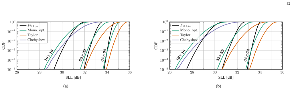
The beampattern is described by a tapering-window-dependent base function evaluated along a deformation determined by the array architecture and signal bandwidth. Element-wise errors generate weighted replicas of the ideal beampattern whose amplitudes are given by the discrete Fourier transform of the mismatch sequence. This formulation yields an approximation of the maximum sidelobe level distribution under random gain and phase mismatches.
What carries the argument
Frequency-domain framework that represents the beampattern as a base function deformed by array and bandwidth parameters, with mismatches analyzed as spectral replicas via their discrete Fourier transform.
If this is right
- Derives an approximation of the maximum sidelobe level distribution under random gain and phase mismatches.
- Enables yield-oriented design of phased arrays by predicting statistical performance directly from mismatch statistics.
- Supports rapid design-space exploration without relying on computationally intensive Monte-Carlo simulations.
- Characterizes global beampattern metrics for arbitrary array architectures and signal bandwidths.
Where Pith is reading between the lines
- The replica model may extend to delay mismatches or other per-element imperfections not treated in the main derivation.
- Designers could invert the distribution approximation to choose manufacturing tolerances that meet a target yield probability.
- The same spectral decomposition could be applied to other global metrics such as main-lobe width or integrated sidelobe ratio.
Load-bearing premise
The base-function-plus-deformation model fully captures global beampattern metrics such as maximum sidelobe level for arbitrary array architectures and signal bandwidths, and random mismatches can be treated via their discrete Fourier transform without structured patterns or angle-dependent statistics.
What would settle it
A Monte-Carlo simulation or hardware measurement on a linear or planar array showing that the empirical distribution of maximum sidelobe level under random gain and phase mismatches deviates from the predicted approximation.
Figures
read the original abstract
Practical implementations of phased arrays suffer from per-antenna gain, phase, and delay mismatches, which can significantly worsen the maximum sidelobe level (SLL) of beampatterns. The existing literature either analyzes specific structured mismatch patterns or derives per-angle marginal statistics under random mismatches, which fail to characterize global beampattern metrics such as the maximum SLL. To address this limitation, we propose a frequency-domain framework in which the beampattern is described by a tapering-window-dependent base function evaluated along a deformation determined by the array architecture and signal bandwidth. This formulation enables a spectral analysis of mismatches, revealing that element-wise errors generate weighted replicas of the ideal beampattern whose amplitudes are given by the discrete Fourier transform of the mismatch sequence. Building on this insight, we derive an approximation of the maximum SLL distribution under random gain and phase mismatches. The resulting expressions enable yield-oriented design and rapid design-space exploration without relying on computationally intensive Monte-Carlo simulations.
Editorial analysis
A structured set of objections, weighed in public.
Referee Report
Summary. The manuscript proposes a frequency-domain framework for phased-array beampatterns under per-element gain and phase mismatches. It models the pattern as a tapering-window base function evaluated along an architecture- and bandwidth-dependent deformation, shows that element-wise mismatches produce weighted replicas of the ideal pattern whose amplitudes are the DFT of the mismatch sequence, and derives an approximation to the distribution of the maximum sidelobe level (SLL) under random mismatches to support yield-oriented design without Monte-Carlo simulation.
Significance. If the approximation and its supporting spectral analysis hold with quantified error bounds for the claimed range of array architectures and bandwidths, the work would supply a practical, low-cost alternative to Monte-Carlo sampling for predicting global beampattern metrics, which is a useful contribution to array design literature.
major comments (2)
- [Abstract and §3] Abstract and §3 (frequency-domain framework): the central claim that element-wise errors generate weighted replicas whose amplitudes are given by the DFT of the mismatch sequence holds exactly only under uniform linear sampling of the array manifold. For arbitrary (non-equispaced) element positions the mismatch multiplication becomes a non-uniform DFT; the replica amplitudes therefore lose their closed-form DFT character and the subsequent max-SLL distribution approximation no longer follows directly.
- [Abstract] Abstract: the manuscript states that an approximation of the maximum SLL distribution is derived, yet supplies neither the explicit expression, the error bound relative to the exact distribution, nor any numerical validation against Monte-Carlo trials; without these the support for the central practical claim cannot be assessed.
minor comments (1)
- [§2] Notation for the deformation variable and the tapering-window base function should be introduced with a single consistent symbol set and an explicit statement of the narrowband assumption.
Simulated Author's Rebuttal
We thank the referee for the careful review and constructive comments. We address each major comment below.
read point-by-point responses
-
Referee: [Abstract and §3] Abstract and §3 (frequency-domain framework): the central claim that element-wise errors generate weighted replicas whose amplitudes are given by the DFT of the mismatch sequence holds exactly only under uniform linear sampling of the array manifold. For arbitrary (non-equispaced) element positions the mismatch multiplication becomes a non-uniform DFT; the replica amplitudes therefore lose their closed-form DFT character and the subsequent max-SLL distribution approximation no longer follows directly.
Authors: We agree that the exact DFT equivalence holds for uniformly sampled arrays. The manuscript develops the framework and all subsequent results under the assumption of uniform linear arrays (ULAs), which is the standard setting for such spectral analyses in the phased-array literature. For non-uniform geometries the mismatch effect would indeed map to a non-uniform DFT. We will revise the abstract, introduction, and §3 to state this assumption explicitly and note the scope limitation. revision: yes
-
Referee: [Abstract] Abstract: the manuscript states that an approximation of the maximum SLL distribution is derived, yet supplies neither the explicit expression, the error bound relative to the exact distribution, nor any numerical validation against Monte-Carlo trials; without these the support for the central practical claim cannot be assessed.
Authors: The explicit approximation to the max-SLL distribution appears in §4 (Eqs. 12–15). Error bounds relative to the exact distribution are derived in Appendix B. Direct numerical comparisons to Monte-Carlo trials for the claimed range of array sizes and bandwidths are shown in §5 (Figs. 3–5). We will revise the abstract to reference these expressions and validations so that the support for the central claim is immediately evident. revision: partial
Circularity Check
No circularity detected in derivation chain
full rationale
The paper introduces a frequency-domain base-function-plus-deformation model and derives the DFT-replica property for mismatch effects as a direct mathematical consequence of that modeling choice applied to the array factor. No step reduces by construction to a fitted parameter renamed as prediction, a self-citation load-bearing premise, or an ansatz imported from the authors' prior work. The subsequent max-SLL distribution approximation follows from the spectral analysis without self-referential closure. The provided text contains no self-citations that justify core claims, and the framework is presented as an independent modeling contribution rather than a tautology.
Axiom & Free-Parameter Ledger
Reference graph
Works this paper leans on
-
[1]
Millimeter wave mobile communications for 5G cellular: It will work!
T. S. Rappaport, S. Sun, R. Mayzus, H. Zhao, Y . Azar, K. Wang, G. N. Wong, J. K. Schulz, M. Samimi, and F. Gutierrez, “Millimeter wave mobile communications for 5G cellular: It will work!”IEEE Access, vol. 1, pp. 335–349, May 2013
2013
-
[2]
Millimeter- wave massive MIMO: the next wireless revolution?
A. L. Swindlehurst, E. Ayanoglu, P. Heydari, and F. Capolino, “Millimeter- wave massive MIMO: the next wireless revolution?”IEEE Commun. Mag., vol. 52, no. 9, pp. 56–62, Sep. 2014
2014
-
[3]
Challenges and opportunities for circuits and systems for next generation satellite payloads [Feature],
P. Angeletti and S. D’Addio, “Challenges and opportunities for circuits and systems for next generation satellite payloads [Feature],”IEEE Circuits Syst. Mag., vol. 25, no. 4, pp. 38–54, 2025
2025
-
[4]
No more “no service
L. Laursen, “No more “no service”: Cellphones will increasingly text via satellite,”IEEE Spectr., vol. 60, no. 1, pp. 52–55, Jan. 2023
2023
-
[5]
Brookner,Practical Phased Array Antenna Systems
E. Brookner,Practical Phased Array Antenna Systems. Artech House, 1991
1991
-
[6]
True time delay in phased arrays,
R. Rotman, M. Tur, and L. Yaron, “True time delay in phased arrays,” Proc. IEEE, vol. 104, no. 3, pp. 504–518, Mar. 2016
2016
-
[7]
0.78– 1.22◦ RMS phase error, 0.14–0.32 dB RMS gain error, K-band 4-channel phased array receiver IC for Satcom on the move (SOTM),
Y . Zhang, F. Huang, X. Tang, Z. Wei, Y . Cao, J. Li, and Z. Li, “ 0.78– 1.22◦ RMS phase error, 0.14–0.32 dB RMS gain error, K-band 4-channel phased array receiver IC for Satcom on the move (SOTM),”IEEE Trans. Circuits Syst. II, vol. 71, no. 12, pp. 4869–4873, Jul. 2024
2024
-
[8]
Evaluation of a planar reconfigurable phased array antenna driven by a multi-channel beamforming module at Ka band,
A. T. Muriel-Barrado, J. Calatayud-Maeso, A. Rodríguez-Gallego, P. Sánchez-Olivares, J. M. Fernández-González, and M. Sierra-Pérez, “Evaluation of a planar reconfigurable phased array antenna driven by a multi-channel beamforming module at Ka band,”IEEE Access, vol. 9, pp. 63 752–63 766, 2021
2021
-
[9]
Co-design of a K- band phase shifter with low RMS phase/amplitude errors for Satcom applications,
J. Hu, D. Zhang, C. Xie, Q. Feng, and K. Ma, “Co-design of a K- band phase shifter with low RMS phase/amplitude errors for Satcom applications,”IEEE Microwave and Wireless Technology Letters, vol. 36, no. 2, pp. 305–308, Feb. 2026
2026
-
[10]
Impact analysis and calibration methods of excitation errors for phased array antennas,
G. He, X. Gao, and R. Zhang, “Impact analysis and calibration methods of excitation errors for phased array antennas,”IEEE Access, vol. 9, pp. 59 010–59 026, Apr. 2021
2021
-
[11]
Average and worst-case analysis of MIMO beamforming loss due to hardware impairments,
X. Chen, M. Crussière, and L. L. Magoarou, “Average and worst-case analysis of MIMO beamforming loss due to hardware impairments,” Nov. 2025. [Online]. Available: https://arxiv.org/abs/2511.05090
-
[12]
Robust adaptive beamform- ing using worst-case performance optimization: a solution to the signal mismatch problem,
S. V orobyov, A. Gershman, and Z.-Q. Luo, “Robust adaptive beamform- ing using worst-case performance optimization: a solution to the signal mismatch problem,”IEEE Trans. Signal Process., vol. 51, no. 2, pp. 313–324, Feb. 2003
2003
-
[13]
Design of error tolerance of a phased array,
J. Hsiao, “Design of error tolerance of a phased array,”Electron. Lett., vol. 21, pp. 834–836, Sep. 1985
1985
-
[14]
Improved statistical model on the effect of random errors in the phase and amplitude of element excitations on the array radiation pattern,
A. J. van den Biggelaar, U. Johannsen, P. Mattheijssen, and A. B. Smolders, “Improved statistical model on the effect of random errors in the phase and amplitude of element excitations on the array radiation pattern,”IEEE Trans. Antennas Propag., vol. 66, no. 5, pp. 2309–2317, May 2018
2018
-
[15]
Maximum ratio transmission,
T. Lo, “Maximum ratio transmission,”IEEE Trans. Commun., vol. 47, no. 10, pp. 1458–1461, Oct. 1999
1999
-
[16]
Design of monopulse antenna difference patterns with low sidelobes,
E. T. Bayliss, “Design of monopulse antenna difference patterns with low sidelobes,”Bell Labs Tech. J., vol. 47, no. 5, pp. 623–650, May-June 1968
1968
-
[17]
Beamwidth of phased arrays,
M. Plotkin, “Beamwidth of phased arrays,”IEEE Trans. Antennas Propag., vol. 21, no. 5, pp. 695–697, Sep. 1973
1973
-
[18]
Antenna array pattern synthesis via convex optimization,
H. Lebret and S. Boyd, “Antenna array pattern synthesis via convex optimization,”IEEE Trans. Signal Process., vol. 45, no. 3, pp. 526–532, Mar. 1997
1997
-
[19]
CVX: Matlab software for disciplined convex programming, version 2.0,
CVX Research, Inc., “CVX: Matlab software for disciplined convex programming, version 2.0,” https://cvxr.com/cvx, Aug. 2012
2012
-
[20]
Graph implementations for nonsmooth convex programs,
M. Grant and S. Boyd, “Graph implementations for nonsmooth convex programs,” inRecent Advances in Learning and Control, ser. Lecture Notes in Control and Information Sciences, V . Blondel, S. Boyd, and H. Kimura, Eds. Springer-Verlag Limited, 2008, pp. 95–110, http: //stanford.edu/~boyd/graph_dcp.html
2008
-
[21]
A current distribution for broadside arrays which optimizes the relationship between beam width and side-lobe level,
C. Dolph, “A current distribution for broadside arrays which optimizes the relationship between beam width and side-lobe level,”Proc. IRE, vol. 34, no. 6, pp. 335–348, Jun. 1946
1946
-
[22]
Discussion on
H. Riblet, “Discussion on "A current distribution for broadside arrays which optimizes the relationship between beam width and side-lobe level" (C. L. Dolph),”Proc. IRE, vol. 35, no. 5, pp. 489–492, May 1947
1947
-
[23]
Design of line-source antennas for narrow beamwidth and low side lobes,
T. Taylor, “Design of line-source antennas for narrow beamwidth and low side lobes,”Transactions of the IRE Professional Group on Antennas and Propagation, vol. 3, no. 1, pp. 16–28, Jan. 1955
1955
-
[24]
Jakowatz, D
C. Jakowatz, D. Wahl, P. Eichel, D. Ghiglia, and P. Thompson,Spotlight- Mode Synthetic Aperture Radar: A Signal Processing Approach, S. S. M. Inc., Ed. Springer New York, 1996
1996
-
[25]
On the use of windows for harmonic analysis with the discrete Fourier transform,
F. Harris, “On the use of windows for harmonic analysis with the discrete Fourier transform,”Proc. IEEE, vol. 66, no. 1, pp. 51–83, Jan. 1978
1978
-
[26]
Effect of time-delay errors on the beam pattern of a linear array,
D. Gray, “Effect of time-delay errors on the beam pattern of a linear array,”IEEE J. Ocean. Eng., vol. 10, no. 3, pp. 269–277, Jul. 1985
1985
-
[27]
Analysis of worst-case phase quantization sidelobes in focused beamforming,
S. Holm and K. Kristoffersen, “Analysis of worst-case phase quantization sidelobes in focused beamforming,”IEEE Trans. Ultrason., Ferroelectr., Freq. Control, vol. 39, no. 5, pp. 593–599, Sep. 1992
1992
-
[28]
Proper complex random processes with applications to information theory,
F. Neeser and J. Massey, “Proper complex random processes with applications to information theory,”IEEE Trans. Inf. Theory, vol. 39, no. 4, pp. 1293–1302, Jul. 1993
1993
-
[29]
Spectral impact of mismatches in interleaved ADCs,
J. Guichemerre, R. Reutemann, T. Burger, and C. Studer, “Spectral impact of mismatches in interleaved ADCs,”IEEE Int. Symp. Circuits and Syst. (ISCAS), 2026
2026
-
[30]
Mailloux,Phased Array Antenna Handbook, Third Edition
R. Mailloux,Phased Array Antenna Handbook, Third Edition. Artech House Publishers, 2017
2017
-
[31]
Efficient and physically consistent modeling of reconfigurable electromagnetic structures,
A. Stutz-Tirri, G. Schwan, and C. Studer, “Efficient and physically consistent modeling of reconfigurable electromagnetic structures,”IEEE Open J. Commun. Soc., vol. 6, pp. 1610–1633, Feb. 2025
2025
discussion (0)
Sign in with ORCID, Apple, or X to comment. Anyone can read and Pith papers without signing in.