REVIEW 4 major objections 5 minor 25 references
Performance Study of Strongly Coupled Magnetic Resonance
T0 review · 4 major / 5 minor · reviewed 2026-08-14 · deepseek-v4-flash
Pith's one-line read This paper reports that a four-coil strongly coupled magnetic resonance prototype resonates at approximately 12 MHz and transfers power most effectively at a transmitter–receiver distance of 36 cm.
desk verdict The 12 MHz claim does not survive contact with the paper's own Table I: 24 µH and 1048 µF resonate near 1 kHz, not 12 MHz, so the central experimental verification is not reproducible as written. read the letter →
The pith
A machine-rendered reading of the paper's core claim, the machinery that carries it, and where it could break.
The reading
What carries the argument
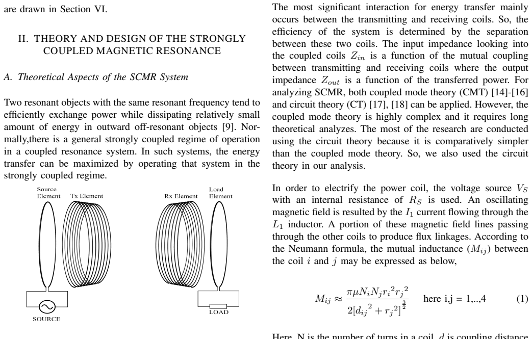
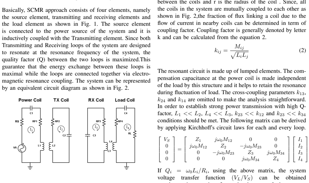
The central object is the four-coil SCMR link—source and load loops inductively coupled to two high-Q helical resonators—whose behavior is captured by an equivalent circuit of four mutually coupled loops. The Kirchhoff matrix for that circuit yields the voltage transfer function $|S_{21}|$ of equation (3), and the resonance condition $f_r = 1/(2\pi\sqrt{LC})$ together with the quality-factor formulas for helical resonators predicts where the link should operate. The experimental machinery is a DDS signal generator, an amplifier, a class E rectifier, and four coils, with output voltage used as the measured proxy for transferred power. This same circuit reading is what lets the paper identify the double-peaked output curve as frequency splitting.
What would settle it
Measure the resonant coils directly, either with a network analyzer or by sweeping the output voltage over frequency, and check where the actual peak appears. The Table I values predict roughly 1 kHz from $f_r = 1/(2\pi\sqrt{LC})$, whereas the paper reports a 12 MHz peak; reading the actual capacitance $C_2$ and $C_3$ with an LCR meter would settle whether the claimed resonance is real or an artifact of a misprinted component value.
Extended reading notes
Core claim
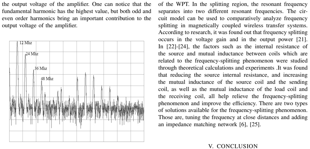
The paper claims that a prototype four-coil strongly coupled magnetic resonance system, built with 16 cm radius eight-turn helical resonators and the component values in Table I, resonates at approximately 12 MHz, and that this resonant frequency is verified by the output-voltage-versus-frequency curve with its characteristic frequency-splitting double peak. At that frequency the optimal transmitter–receiver separation is measured to be 36 cm, where the output voltage is highest. The same experiments show that the resonant link attenuates the harmonics produced by the power amplifier, acting as a band-pass filter, and the simulations indicate that the frequency giving the maximum quality factor is strongly tied to the coil radius. The paper also observes frequency splitting directly and discusses the standard remedies of retuning or impedance matching.
Load-bearing premise
The load-bearing premise is that the component values in Table I are accurate as printed—in particular that the resonant coils have $L_2 = L_3 = 24\,\mu\mathrm{H}$ and $C_2 = C_3 = 1048\,\mu\mathrm{F}$ while resonating at 12 MHz; using the paper's own formula $f_r = 1/(2\pi\sqrt{LC})$, those values place resonance near 1 kHz, not 12 MHz, so if the capacitance is misprinted or the coils do not actually resonate at 12 MHz the reported verification loses its footing.
Editorial extensions
If this is right
- The measured output-voltage curve implies that the oscillator and amplifier must stay locked to 12 MHz; stepping away from resonance cuts the delivered voltage.
- The 36 cm optimum is a concrete design constraint for this coil geometry at 12 MHz: closer separations enter the frequency-splitting regime and larger separations weaken coupling.
- The resonant network's band-pass behavior means a practical SCMR transmitter can tolerate a moderately nonlinear power amplifier without radiating strong harmonics.
- Frequency splitting implies that a fixed 12 MHz drive is suboptimal at close distances, so the cited remedies—retuning the frequency or adding an impedance matching network—are needed there.
- The simulations indicate that coil radius shifts the frequency of maximum quality factor, giving designers a geometric tuning lever in addition to capacitance.
Reading between the lines
- Going beyond the paper, the frequency-splitting double peak suggests an adaptive transmitter could lock onto either split peak to stabilize power delivery as the receiver moves, turning a known nuisance into a control signal.
- Going beyond the paper, because the resonant link rejects out-of-band harmonics, the same coils could carry both power and data by modulating a subcarrier, effectively merging the power link with a communication channel.
- Going beyond the paper, the observed dependence of maximum-Q frequency on coil radius implies that a mechanically tunable helix—varying radius or turn spacing—could retune the link without external capacitors, a testable extension of the described fixture.
Signed reviews
Editorial analysis
A structured set of objections, weighed in public.
Referee Report
Summary. The paper reports an experimental and simulation study of a four-coil strongly coupled magnetic resonance (SCMR) wireless power transfer system. The authors derive circuit-theory expressions for the transfer function and quality factor, describe a prototype with the parameters listed in Table I, and present measurements of output voltage versus frequency to verify a resonant frequency of approximately 12 MHz. They also report a measured optimal transmitter-receiver distance of 36 cm at resonance and discuss the influence of harmonics and frequency splitting. The central claims are that the prototype resonates near 12 MHz and that the optimal separation at this frequency is 36 cm.
Significance. If the experimental claims are reliable, the paper would provide a useful application-oriented confirmation of SCMR principles and a demonstration of frequency splitting in a physical prototype. The authors are to be credited for building a working four-coil system and for attempting to verify resonance through direct voltage measurements rather than relying only on simulation. The harmonic analysis and the observation of frequency splitting are also potentially interesting. However, the significance is limited by the fact that the experimental results are not reproducible from the stated circuit parameters, and by the absence of any error analysis, repeated trials, or detailed measurement protocols. The architecture and theory are standard in the wireless power transfer literature, so the contribution rests almost entirely on the experimental evidence, which is currently not trustworthy.
major comments (4)
- [Table I and Eq. (5)] The listed resonant coil capacitance C2=C3=1048 µF is inconsistent with the claimed resonant frequency fr=12 MHz and the stated inductance L2=L3=24 µH. Using Eq. (5), fr=1/(2π√LC), the resonance of this L-C combination is approximately 1 kHz, not 12 MHz. Conversely, achieving 12 MHz with L=24 µH requires C≈7.3 pF, a factor of about 1.4×10^8 smaller than the tabulated value. This is a load-bearing internal inconsistency: the voltage peak near 12 MHz in Fig. 5 cannot be attributed to the resonance of the described resonators. The authors must correct the capacitance value or, if the reported value is not a typo, provide a full explanation of how the system actually resonated at 12 MHz. They should also specify whether lumped capacitors were used or whether the coils were self-resonant, and describe how the resonant frequency was independently measured (e.g., impedance or S-parameter measurement).
- [Section IV-B and Fig. 5] The experimental verification of the resonant frequency consists of a single output-voltage-versus-frequency curve with no error bars, no indication of repeated trials, and no description of the measurement conditions (e.g., source power, load resistance, coil separation, how the output voltage was sensed). Without these details, the shape of the curve—including the claimed frequency-splitting 'two hills and one valley'—cannot be quantitatively assessed. The authors should provide the full experimental protocol, the number of measurements per frequency point, and an estimate of measurement uncertainty. If the frequency splitting is an important observation, it should be reproduced at several distances and compared with the circuit model.
- [Section IV-C and Fig. 6] The optimal distance of 36 cm is reported from a single curve of output voltage versus distance, with no error bars, no repeated trials, and no description of how the distance was varied or how the coils were aligned. Moreover, output voltage alone is not a direct measure of wireless power transfer efficiency, especially if the impedance match between the source, coils, and load changes with distance. The authors should report measured efficiency or at least characterize the load and source impedances, and they should provide multiple measurements to demonstrate that the optimum at 36 cm is reproducible.
- [Section II-B and Table I] The text in Section II-B states that helical resonators use distributed inductance and capacitance and therefore 'avoid the use of external capacitors to get a desired resonant frequency.' Yet Table I lists explicit lumped capacitances C2=C3=1048 µF for the resonant coils. This contradiction must be resolved. If the prototype used self-resonant helices, Table I should not list lumped capacitances and Eq. (5) is not directly applicable to the distributed resonator. If lumped capacitors were used, the text in Section II-B is misleading and the actual capacitance values must be stated correctly.
minor comments (5)
- [Abstract] The sentence 'Since the energy exchange capability of resonant objects higher than non-resonant objects' contains a grammatical error; 'higher' should be 'is higher' or the sentence should be rephrased. Also, the statement is imprecise—resonant objects exchange energy more efficiently with other resonant objects, not simply 'higher' in an absolute sense.
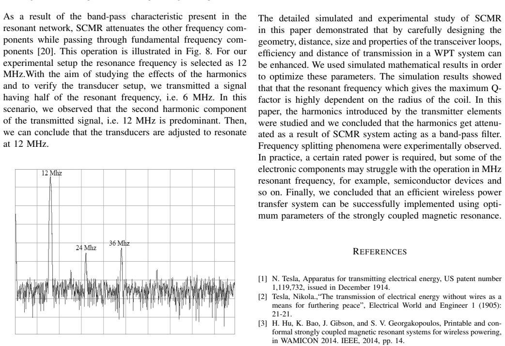
- [Section IV-D.1] The harmonic experiment transmits a 6 MHz signal and observes a dominant 12 MHz second harmonic at the receiver. This provides indirect evidence of resonance near 12 MHz, but the conclusion would be strengthened by a direct measurement of the resonator's impedance or transmission response around the resonant frequency.
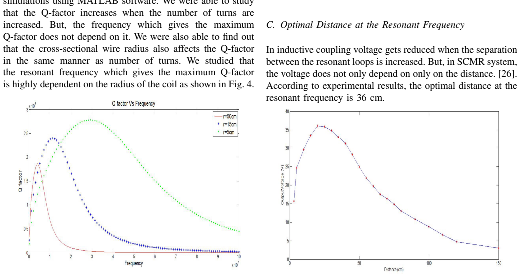
- [Section IV-A and Fig. 4] The simulation results are described only qualitatively. The parameters used in the MATLAB simulation (e.g., the range of radii, number of turns, wire radius, and the material resistivity) should be listed so that the Q-factor curves in Fig. 4 can be reproduced.
- [References] Reference [6] ('Sample et al., IEEE Trans. Ind. Electron.') has bibliographic data that appear to belong to the Science paper by Kurs et al. (Reference [9]): volume 317, number 5834, pages 83-86. The authors should verify and correct the reference details.
- [Section VI (Conclusion)] The conclusion repeats the claim that the simulation and experiments demonstrate enhanced efficiency and distance 'by carefully designing the geometry, distance, size and properties,' but it does not summarize the specific quantitative results (e.g., resonant frequency confirmation, optimal distance, or efficiency values). A brief summary of measured values would strengthen the conclusion.
Circularity Check
No significant circularity: all central results are direct measurements, not derived from fitted parameters or self-cited constraints.
full rationale
The paper's central claims are experimental: the prototype output-voltage peak near 12 MHz (Fig. 5) and the optimal 36 cm distance at that frequency (Fig. 6). These are measured results, not quantities derived by fitting inputs and then renamed as predictions. The design table lists fr = 12 MHz as a target parameter, and the later measurement that the prototype peaks near 12 MHz is a consistency check between design and implementation, not a circular derivation: the resonance is not calculated from the claimed claim, it is observed. Equation (5) is the standard textbook LC resonance formula and is not derived from the experimental outcome. Citations to prior work are background references for SCMR theory and frequency splitting; none is used as a load-bearing uniqueness theorem or as an unverified self-citation that forces the conclusion. The paper does exhibit a serious internal inconsistency between Table I (C2 = C3 = 1048 µF, L2 = L3 = 24 µH) and Eq. (5) with fr = 12 MHz, since those values imply kHz-range resonance, but that is a correctness/verifiability problem, not a circularity problem. There is no step in which an equation or fitted parameter reduces by construction to the result it is supposed to support, so the circularity score is 0.
Assumptions & free parameters
free parameters (3)
- Resonant coil capacitance C2, C3 =
1048 µF (as listed in Table I)
- Coil geometry (radius r=16 cm, wire radius rc=3 mm, number of turns N=8) =
r=16 cm, rc=3 mm, N=8
- Source/load coil inductance and resistance, and resonant coil resistance =
L1=L4=1 µH, R1=R4=0.02 Ω, R2=R3=0.04 Ω as listed in Table I
assumptions (4)
- standard math Mutual inductance between circular coils is given by the Neumann formula (Eq. 1).
- domain assumption The four-coil system can be modeled by Kirchhoff's laws with only nearest-neighbor coupling, neglecting k13, k24, and k14.
- domain assumption Helix resonators behave as series RLC circuits whose self-inductance and resistances follow Eqs. (8)-(10).
- domain assumption Output voltage is a valid proxy for power transfer efficiency.
Cite this review
Pith. "Pith review of Performance Study of Strongly Coupled Magnetic Resonance." pith.science (2026). https://pith.science/paper/PYEIIU6S
@misc{pith2026190802541,
  author       = {Pith},
  title        = {Pith review of: Performance Study of Strongly Coupled Magnetic Resonance},
  year         = {2026},
  howpublished = {\url{https://pith.science/paper/PYEIIU6S}},
  note         = {Machine review of arXiv:1908.02541}
}
read the original abstract
Strongly Coupled Magnetic Resonance (SCMR) uses electromagnetic resonance in order to efficiently transfer power wirelessly over mid-range distances. Since the energy exchange capability of resonant objects higher than non-resonant objects, strongly coupled systems are able to achieve more efficient energy transfer than other wireless power transfer systems. The paper presents detailed experimental and simulated analysis of the performance of the SCMR system. A prototype of the SCMR system was implemented and experiments were conducted to analyze the performance of the system. Finally, the resonant frequency of the system was experimentally verified and the factors influencing the wireless power transfer were also studied
Figures

Figures from the paper (4 more)

Reference graph
Works this paper leans on
-
[1]
N. Tesla, Apparatus for transmitting electrical energy, US patent number 1,119,732, issued in December 1914
work page 1914
-
[2]
The transmission of electrical energy without wires as a means for furthering peace
Tesla, Nikola.,“The transmission of electrical energy without wires as a means for furthering peace”, Electrical World and Engineer 1 (1905): 21-21
work page 1905
-
[3]
H. Hu, K. Bao, J. Gibson, and S. V . Georgakopoulos, Printable and con- formal strongly coupled magnetic resonant systems for wireless powering, in W AMICON 2014. IEEE, 2014, pp. 14
work page 2014
-
[4]
A. Rajaram, D. N. K. Jayakody, K. Srinivasan, B. Chen, and V . Sharma,Opportunistic-harvesting: Rf wireless power transfer scheme for multipleaccess relays system,IEEE Access, vol. 5, pp. 1608416099, 2017
work page 2017
-
[5]
D. N. K. Jayakody, J. Thompson, S. Chatzinotas, and S. Durrani,Wireless Information and Power Transfer: A New Paradigm for Green Communi- cations. Springer, 2017
work page 2017
-
[6]
A. P. Sample, D. T. Meyer, and J. R. Smith, “Analysis, experimental results, and range adaptation of magnetically coupled resonators for wireless power transfer, IEEE Trans. Ind. Electron., vol. 317, no. 5834, pp. 83-86, July 2007
work page 2007
-
[7]
A. Karalis, J. D. Joannopoulos, and M. Soljacic, “Efficient wireless non- radiative mid-range energy transfer, Ann. Phys., vol. 323, pp. 3448, Jan. 2008
work page 2008
-
[8]
A. Rajaram, Rabia Khan, T. Selvakumar , Dushantha Nalin K. Jayakody, R. Dinis and S. Panic “Novel SWIPT Schemes for 5G Wireless Networks, MDPI Sensors, 19(5), 1169, 2019
work page 2019
Show all 25 references
-
[9]
A. Kurs, A. Karalis, R. Moffatt, J. Joannopoulos, P. Fisher, and M. Sol- jacic, “Wireless power transfer via strongly coupled magnetic resonances, Science, vol. 317, no. 5834, pp. 83-86, July 2007
2007
-
[10]
Niculae, M
Dumitriu, D. Niculae, M. Iordache, L. Mandache, and G. Zainea, Onwireless power transfer, in2012 International Conference on Applied andTheoretical Electricity (ICATE). IEEE, 2012, pp. 16
2012
-
[11]
Parameters Optimization for Magnetic Resonance Coupling Wireless Power Transmission
C. Li, H. Zhang and X. Jiang, “Parameters Optimization for Magnetic Resonance Coupling Wireless Power Transmission”, 2017
2017
-
[12]
Imura, Y
Koh Kim Ean, Beh Teck Chuan and T. Imura, Y . Hori, “Novel band- pass filter model for multi-receiver wireless power transfer via magnetic resonance coupling and power division, 2012 IEEE 13th Annual Wireless and Microwave Technology Conference (W AMICON), vol., no., pp.1-6, 15...
2012
-
[13]
Lee Jaechun and Nam Sangwook,“Fundamental Aspects of Near-Field Coupling Small Antennas for Wireless Power Transfer, IEEE Transactions on Antennas and Propagation, vol.58, no.11, pp.3442-3449, Nov. 2010
2010
-
[14]
Long range inductive power transfer with superconducting oscillators
R. Sedwick, “Long range inductive power transfer with superconducting oscillators”, Annals of Physics, vol. 325, no. 2, pp. 287-299, 2010
2010
-
[15]
Analysis of Wireless Energy Transmission for Implantable Device Based on Coupled Magnetic Resonance
N. Yin, G. Xu, Q. Yang, J. Zhao, X. Yang, J. Jin, W. Fu and M. Sun, “Analysis of Wireless Energy Transmission for Implantable Device Based on Coupled Magnetic Resonance”, IEEE Transactions on Magnetics, vol. 48, no. 2, pp. 723-726, 2012
2012
-
[16]
Relay Effect of Wireless Power Transfer Using Strongly Coupled Magnetic Resonances
F. Zhang, S. Hackworth, W. Fu, C. Li, Z. Mao and M. Sun, “Relay Effect of Wireless Power Transfer Using Strongly Coupled Magnetic Resonances”, IEEE Transactions on Magnetics, vol. 47, no. 5, pp. 1478- 1481, 2011
2011
-
[17]
Two-side Impedance Matching for Maximum Wireless Power Transmission
S. Barman, A. Reza, N. Kumar and T. Anowar, “Two-side Impedance Matching for Maximum Wireless Power Transmission”, IETE Journal of Research, vol. 62, no. 4, pp. 532-539, 2015
2015
-
[18]
Design and Optimization of a 3-Coil Inductive Link for Efficient Wireless Power Transmission
M. Kiani, Uei-Ming Jow and M. Ghovanloo, “Design and Optimization of a 3-Coil Inductive Link for Efficient Wireless Power Transmission”, IEEE Transactions on Biomedical Circuits and Systems, vol. 5, no. 6, pp. 579-591, 2011
2011
-
[19]
The influence of the frequency on the efficiency and on the power quality of a contactless power transfer system
I. Sirbu, “The influence of the frequency on the efficiency and on the power quality of a contactless power transfer system”, 2015 IEEE 15th International Conference on Environment and Electrical Engineering (EEEIC), 2015
2015
-
[20]
Design Consideration and Comparison of Wireless Power Transfer via Harmonic Current for PHEV and EV Wireless Charging
H. Zeng, S. Yang and F. Peng, “Design Consideration and Comparison of Wireless Power Transfer via Harmonic Current for PHEV and EV Wireless Charging”, IEEE Transactions on Power Electronics, vol. 32, no. 8, pp. 5943-5952, 2017
2017
-
[22]
Frequency-Splitting Analysis of Four- Coil Resonant Wireless Power Transfer
Y . Zhang, Z. Zhao and K. Chen, “Frequency-Splitting Analysis of Four- Coil Resonant Wireless Power Transfer”, IEEE Transactions on Industry Applications, vol. 50, no. 4, pp. 2436-2445, 2014
2014
-
[23]
Frequency Splitting Analysis of Wireless Power Transfer System Based on T-type Transformer Model
L. Jianyu, T. Houjun and G. Xin, “Frequency Splitting Analysis of Wireless Power Transfer System Based on T-type Transformer Model”, Electronics and Electrical Engineering, vol. 19, no. 10, 2013
2013
-
[24]
”Distance-Insensitive Wireless Power Transfer Using Mixed Electric and Magnetic Coupling for Frequency Splitting Suppression
X. Zhang, C. Xue and J. Lin, “”Distance-Insensitive Wireless Power Transfer Using Mixed Electric and Magnetic Coupling for Frequency Splitting Suppression”, IEEE Transactions on Microwave Theory and Techniques, pp. 1-10, 2017
2017
-
[25]
C. B. Teck, T. Imura, M. Kato, and Y . Hori,“Basic study of improving efficiency of wireless power transfer via magnetic resonance coupling based on impedance matching, in Proc. IEEE Int. Symp. Ind. Electron., pp. 20112016, 2010
2010
-
[26]
Optimization of Wireless Power Transfer via Magnetic Resonance in Different Media
Jonah, Olutola, “Optimization of Wireless Power Transfer via Magnetic Resonance in Different Media” (2013), FIU Electronic Thesesand Dis- sertations, 876
2013
Reviewed August 14, 2026 · model on record in the stance chip above.
Discussion (0). Continue with ORCID to comment.