REVIEW 4 major objections 4 minor 1 cited by
Full-Angle Ray Antenna Array and Omnicell Wireless Communication System
T0 review · 4 major / 4 minor · reviewed 2026-08-05 · deepseek-v4-flash
Pith's one-line read Full-angle ray antenna arrays give uniform 360-degree resolution, higher sum rates, and roughly 38 percent of the hardware cost of ULA-based cell sectoring.
desk verdict A plausible extension of the authors' ray antenna array work, undermined by an unfair element-count comparison and an inconsistent formula for the number of rays. read the letter →
The pith
A machine-rendered reading of the paper's core claim, the machinery that carries it, and where it could break.
The reading
What carries the argument
The central object is the full-angle ray antenna array: N×M low-cost elements arranged into N simple ULAs ('rays'), each of M elements directly connected so that no phase shifters or digital beamforming are required. The key design identity is the ray orientation formula η_n = n arcsin(2/M), which places the null of each ray's main lobe at the peak of its neighbor's lobe; this makes the array sample angle in uniform steps arcsin(2/M), giving the same beamwidth 2 arcsin(2/M) in all directions. A ray selection network chooses which rays connect to RF chains, and the paper notes that greedy selection reduces to a minimum-angle-distance problem, so beam assignment needs no heavy optimization.
What would settle it
Re-run the Section IV comparison with the ULA-based cell sectoring allowed the same total number of antenna elements as the full-angle RAA (12,864 elements) and recompute the 10-user sum rate over the same SNR range; if the omnicell no longer achieves a higher sum rate, the claimed advantage is an artifact of the unequal antenna budget.
Extended reading notes
Core claim
The paper's central claim is that a full-angle RAA—N×M antenna elements partitioned into N directly connected rays with orientations η_n = n arcsin(2/M)—produces a constant beamwidth of 2 arcsin(2/M) in every direction, eliminating the sector boundaries that degrade service in conventional cell sectoring. Because each ray only needs to cover a narrow angular window, directional elements can concentrate energy, whereas a ULA-based hybrid beamforming system samples sin φ non-uniformly and its beams broaden near large angles; a UCA gives uniform resolution but cannot focus with directional elements as effectively. Under the paper's simulations, the omnicell system achieves higher 10-user sum ra
Load-bearing premise
The quantitative claims in Section IV compare an omnicell array with 201×64 = 12,864 elements against a 64-element ULA and a 100-element UCA, under fixed per-element and per-switch prices; if the comparison should instead match total element count or aperture, the claimed advantages would not hold.
Editorial extensions
If this is right
- A single base station at the cell center can replace three sector arrays, removing sector edges and the inter-sector interference they cause.
- Uniform angular resolution means users near former sector boundaries get the same beam gain as users at broadside, so coverage quality becomes direction-independent.
- The omnicell's beam selection can be implemented with a simple minimum-angle-distance rule rather than full joint optimization, lowering scheduling complexity.
- At the paper's stated unit prices, the full-angle RAA hardware costs about 38% of ULA-based sectoring hardware, and remains cheaper for element prices up to $3.8.
- The combination of low cost, uniform resolution, and high sum rate makes the design a candidate for UAV swarm communication and environment sensing.
Reading between the lines
- The cost comparison uses 12,864 RAA elements versus 64 ULA elements; an equal-element-count comparison would likely reduce the cost gap, and the more defensible advantage is trading expensive phase shifters for many cheap elements.
- Since greedy ray selection reduces to minimum-angle-distance, the omnicell's scheduling is essentially nearest-ray user association; simple user-to-ray matching may reproduce much of the sum-rate gain without exhaustive search.
- Uniform angular sampling makes full-angle RAA a natural fit for joint communication and sensing, because a single array could resolve scatterers in all directions with predictable, angle-independent resolution.
- The 10-user uniform-angle simulation may not capture clustered traffic; under spatially clustered users, some rays would carry heavier load, so the omnicell's advantage may depend on angular traffic uniformity.
Editorial analysis
A structured set of objections, weighed in public.
Referee Report
Summary. The paper proposes a full-angle ray antenna array (RAA) architecture, in which a large number of cheap antenna elements are organized into N uniformly oriented simple ULAs (sULAs), each with M directly connected elements. It then introduces an "omnicell" wireless communication system, where a full-angle RAA is deployed at the cell center to provide uniform angular resolution over 360°. The authors derive the array response, define SINR and sum-rate expressions, and compare the proposed system with conventional ULA- and UCA-based cell sectoring through beam-pattern plots, sum-rate simulations under a 3GPP Uma NLOS channel, and a hardware-cost calculation. The claimed contributions are uniform spatial resolution, reduced inter-user interference, higher sum rate, and lower hardware cost relative to sectorized ULA/UCA systems.
Significance. If established, the omnicell concept could be a meaningful step toward low-cost, full-coverage massive MIMO for 6G and joint sensing and communication, because the full-angle RAA avoids per-antenna phase shifters and offers direction-dependent array gain with a simple ray-selection network. The paper provides an analytical array-response model, an SINR formulation, and a comparative simulation framework. These strengths are real. However, the central comparative claims rest on a heavily asymmetric resource comparison and at least one unverified design equation; as presented, the evidence does not yet support the claimed advantages.
major comments (4)
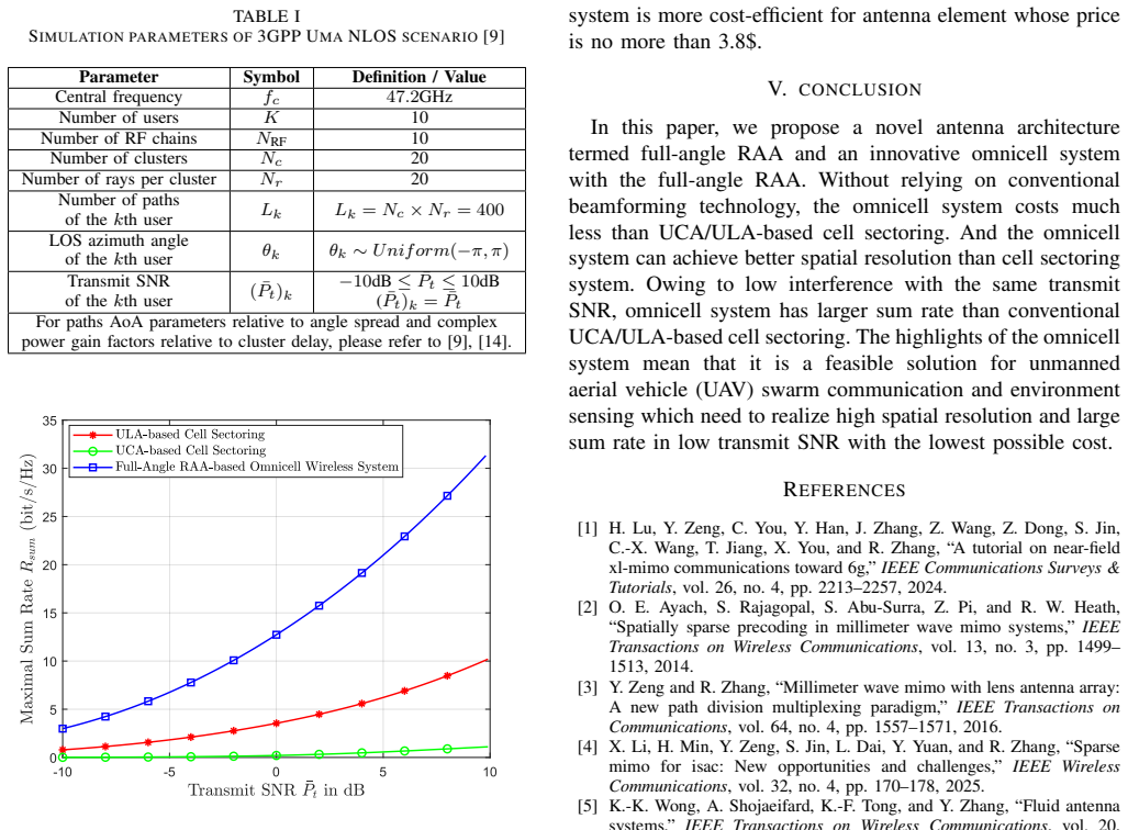
- [Section IV-B, Table I and Section IV-C] The main sum-rate and cost claims compare a full-angle RAA with N×M = 201×64 = 12,864 antenna elements against a ULA benchmark with 64 elements per sector (or 192 total for three sectors) and a UCA with 100 elements. This is a 67–128× element-count asymmetry. Since array gain, resolution, and interference suppression scale strongly with element count, the higher sum rate and finer resolution in Figs. 5–7 are expected even for a conventional array with the same element budget, and do not by themselves demonstrate an advantage of the RAA architecture. The cost comparison in Section IV-C compounds this: the RAA cost formula uses 12,864 elements and only 1,005 switches, while the ULA cost uses 640 phase shifters and 192 elements, so the claimed 37.6% cost is a consequence of the chosen hardware mix and element counts. The authors should provide comparisons at equal total element count, equal
- [Section II, Eq. (9)] The derivation of the number of rays N is omitted and the formula appears inconsistent with the M=4 example used throughout Section IV. For M=4, Eq. (8) gives D = λ/[4 sin(0.5 arcsin(2/M))] ≈ 0.966λ, and Eq. (9) then yields N = floor(2(π − π/12)/(π/6) + 1) = 12, not the N=13 used in Figs. 3, 5, and 6. Using the stated D=6.1 mm at 47.2 GHz gives N=11. Similarly, the approximation N ≈ floor(Mπ) gives floor(4π)=12. Since N determines the total element count and hence both the cost and the sum-rate comparison, this inconsistency is load-bearing and must be corrected or justified.
- [Section IV-B and Table I] The simulation details are insufficient for the central numerical claim. Table I refers to 3GPP Uma NLOS but leaves AoA generation, cluster delays, path powers, and antenna-element radiation patterns for the ULA/UCA benchmarks to unspecified references. The DFT codebook size N' in Eq. (11), the number of codewords for the UCA parametric codebook in Eq. (21), the ray-selection algorithm implementation, and the number of Monte Carlo realizations are not stated. Without these, Fig. 7 cannot be reproduced, and the comparison may depend on undocumented choices such as whether the ULA/UCA use isotropic or directional elements while the RAA uses 3GPP directional elements (Section III, after Eq. (17)). These details should be reported.
- [Section IV-C] The cost model is not justified. The factor 1/2 in the RAA switch-count term N_RF·N/2 appears without explanation: the ray selection network of [7] is said to select N_RF out of N rays, but the number of physical switches needed and whether each switch is single-pole double-throw or more complex is not described. The ULA cost also assumes N_RF×M phase shifters, but for a three-sector ULA system it is unclear whether each sector has its own N_RF RF chains or whether the RF chains are shared across sectors. The claimed cost advantage is directly proportional to these modeling choices, so the cost comparison should be revisited with explicit switch/phase-shifter counts and with equal-capability baselines.
minor comments (4)
- [General] There are numerous typos: "digtial" in the Introduction, "resposne" in Section IV, "cos U LA" in Section IV-C, "U nif orm" in Table I, and "UA V" in the Conclusion. A careful proofread is needed.
- [Eq. (17)] The radiation-pattern expression uses a double negative, G(ζm) = −min[−A_dB(ζm), A_max], which is confusing. Please write the definition directly in dB or as a positive gain function.
- [Section III, Eq. (11)] The DFT codebook size N' is never specified. It should be defined, and the same applies to the number of codewords in the UCA parametric codebook in Eq. (21), where N is already used for the number of array elements.
- [References] References [7] and [14] are the same arXiv paper; this duplicate should be eliminated, and the journal/venue should be updated if available.
Circularity Check
No circular derivation chain: RAA equations and omnicell performance are derived from array geometry and standard SINR/rate expressions; minor self-citations to prior RAA work do not load-bear the new claims, though the comparison basis is asymmetric.
full rationale
The paper's central derivations are self-contained. Section II obtains the RAA response pattern from the sULA geometry (Eqs. (1)-(6)), and the ray orientation rule (7) is justified by null-to-peak alignment derived from (6), not by fitting a target result. The full-angle coverage condition (9) is a coverage/counting relation, not an imported uniqueness theorem. Section III's SINR and sum-rate expressions (13)-(16), (23) are standard definitions, and the Monte Carlo comparison uses the same objective and the same greedy selection algorithm for RAA, ULA, and UCA. The cost model in Section IV-C is an evaluation of stated unit prices and switch counts, not a prediction of a fitted quantity. The main caveat, an asymmetric resource budget (full-angle RAA uses N x M = 201 x 64 = 12,864 elements and 1,005 switches vs 64-element ULAs or 100-element UCA), is a fairness/correctness concern rather than a circular reduction: no equation is defined in terms of the quantity it is said to predict, and no fitted parameter is renamed as a result. The self-citations to [7]/[14] provide the parent RAA architecture and the greedy algorithm, but the paper re-derives the beam pattern and does not use those citations as the sole evidence for its new claims, so they do not make the derivation circular. The score of 2 reflects only the minor self-citation for the inherited RAA model and selection algorithm; no circular step was found.
Assumptions & free parameters
free parameters (2)
- UCA element count N_UCA =
100
- ULA element count M_ULA =
64
assumptions (5)
- domain assumption Each sULA's M elements are directly connected with no phase shifters, yielding the array response in (6).
- domain assumption Adjacent-ray interference is avoided by aligning nulls to peaks, eta_n = n arcsin(2/M) (Eq. 7).
- ad hoc to paper For M >> 1, D is approximately M*lambda/4 and N approximately floor(M*pi); used to set N=201 for M=64.
- domain assumption The 3GPP Uma NLOS channel model with L_k = 400 paths is used for simulations.
- domain assumption The greedy ray-selection algorithm from [7] solves (16) near-optimally.
invented entities (2)
-
Omnicell wireless communication paradigm
-
Full-angle RAA configuration
Cite this review
Pith. "Pith review of Full-Angle Ray Antenna Array and Omnicell Wireless Communication System." pith.science (2026). https://pith.science/paper/S5DPAJVW
@misc{pith2026250905677,
  author       = {Pith},
  title        = {Pith review of: Full-Angle Ray Antenna Array and Omnicell Wireless Communication System},
  year         = {2026},
  howpublished = {\url{https://pith.science/paper/S5DPAJVW}},
  note         = {Machine review of arXiv:2509.05677}
}
read the original abstract
Ray antenna array (RAA) was recently proposed as a novel multi-antenna architecture that arranges multiple massive cheap antenna elements into simple uniform linear arrays (sULAs) with different orientations. Compared with traditional architectures like hybrid analog/digital beamforming with uniform linear array (ULA) and uniform circular array (UCA), RAA has several promising advantages such as significantly reduced hardware cost, higher beamforming gains and the ability of providing uniform angular resolution for all directions. In this paper, we propose a full-angle RAA architecture and an innovative omnicell wireless communication paradigm enabled by full-angle RAA. The proposed full-angle RAA expands RAA's orientation angle to the full angle domain, such that the RAA's advantages can be exploited to all directions. This further enables the new concept of omnicell wireless communication system, with the base station equipped by full-angle RAA and deployed at the center of each cell. Compared to the conventional cell sectoring wireless communication system, the proposed omnicell system is expected to not only significantly reduce the inter-user interference, but also improve the cost efficiency. Extensive analytical and numerical results are provided to compare those key performance indicators such as the spatial resolution and the communication rate of the proposed full-angle RAA based omnicell wireless communication system against the conventional ULA/UCA-based cell sectoring systems.
Figures


Figures from the paper (3 more)


Forward citations
Cited by 1 Pith paper
-
Complementary RL: Towards Efficient Experience-Driven Agent Learning
Complementary RL co-trains a policy actor on sparse outcome rewards and an experience extractor on whether its distilled experiences help the actor succeed, yielding about 10% gains over experience-free agentic RL.
Reference graph
Works this paper leans on
-
[1]
A tutorial on near-field xl-mimo communications toward 6g,
H. Lu, Y . Zeng, C. You, Y . Han, J. Zhang, Z. Wang, Z. Dong, S. Jin, C.-X. Wang, T. Jiang, X. You, and R. Zhang, “A tutorial on near-field xl-mimo communications toward 6g,”IEEE Communications Surveys & Tutorials, vol. 26, no. 4, pp. 2213–2257, 2024
work page 2024
-
[2]
Spatially sparse precoding in millimeter wave mimo systems,
O. E. Ayach, S. Rajagopal, S. Abu-Surra, Z. Pi, and R. W. Heath, “Spatially sparse precoding in millimeter wave mimo systems,”IEEE Transactions on Wireless Communications, vol. 13, no. 3, pp. 1499– 1513, 2014
work page 2014
-
[3]
Millimeter wave mimo with lens antenna array: A new path division multiplexing paradigm,
Y . Zeng and R. Zhang, “Millimeter wave mimo with lens antenna array: A new path division multiplexing paradigm,”IEEE Transactions on Communications, vol. 64, no. 4, pp. 1557–1571, 2016
work page 2016
-
[4]
Sparse mimo for isac: New opportunities and challenges,
X. Li, H. Min, Y . Zeng, S. Jin, L. Dai, Y . Yuan, and R. Zhang, “Sparse mimo for isac: New opportunities and challenges,”IEEE Wireless Communications, vol. 32, no. 4, pp. 170–178, 2025
work page 2025
-
[5]
Fluid antenna systems,
K.-K. Wong, A. Shojaeifard, K.-F. Tong, and Y . Zhang, “Fluid antenna systems,”IEEE Transactions on Wireless Communications, vol. 20, no. 3, pp. 1950–1962, 2021
1950
-
[6]
Movable antennas for wireless communi- cation: Opportunities and challenges,
L. Zhu, W. Ma, and R. Zhang, “Movable antennas for wireless communi- cation: Opportunities and challenges,”IEEE Communications Magazine, vol. 62, no. 6, pp. 114–120, 2024
work page 2024
-
[8]
Beam codebook based beamforming protocol for multi-gbps millimeter-wave wpan systems,
Z. L. Junyi Wanget al., “Beam codebook based beamforming protocol for multi-gbps millimeter-wave wpan systems,”IEEE Journal on Se- lected Areas in Communications, vol. 27, no. 8, pp. 1390–1399, 2009. [9]5G; Study on Channel Model for Frequencies from 0.5 to 100 GHz, document 38.901, Version 16.1.0, 3GPP, Technical Specification (TS), Nov. 2020
work page 2009
-
[10]
Cell-free massive mimo versus small cells,
H. Q. Ngo, A. Ashikhmin, H. Yang, E. G. Larsson, and T. L. Marzetta, “Cell-free massive mimo versus small cells,”IEEE Transactions on Wireless Communications, vol. 16, no. 3, pp. 1834–1850, 2017
work page 2017
Show all 14 references
-
[11]
Uniform circular arrays for smart anten- nas,
P. Ioannides and C. Balanis, “Uniform circular arrays for smart anten- nas,”IEEE Antennas and Propagation Magazine, vol. 47, no. 4, pp. 192–206, 2005
2005
-
[12]
Parametric codebook design for efficient signal transmission using uniform circular arrays,
J. Shin, J. Suh, S. Park, and W. Sung, “Parametric codebook design for efficient signal transmission using uniform circular arrays,”EURASIP Journal on Wireless Communications and Networking, vol. 2021, no. 1, p. 191, 2021
2021
-
[13]
Two decades of array signal processing research: the parametric approach,
H. Krim and M. Viberg, “Two decades of array signal processing research: the parametric approach,”IEEE signal processing magazine, vol. 13, no. 4, pp. 67–94, 2002
2002
-
[14]
Ray antenna array: A novel cost-effective multi-antenna architecture for enhanced wireless commu- nication,
Z. Dong, Z. Zhou, and Y . Zeng, “Ray antenna array: A novel cost-effective multi-antenna architecture for enhanced wireless commu- nication,” 2025. [Online]. Available: https://arxiv.org/abs/2505.18163
2025 arXiv
-
[15]
A. Devices. Admv4728 transmit/receive dual polarization beamformer. Accessed at:2025-8-1. [Online]. Available: https://www.analog.com/en/ products/admv4728.html#documentation
2025
-
[16]
Tgs4302 high power spdt switch
Qorvo. Tgs4302 high power spdt switch. Accessed at: 2025-8-1. [Online]. Available: https://www.qorvo.com/products/p/TGS4302
2025
Reviewed August 5, 2026 · model on record in the stance chip above.
Discussion (0). Sign in to comment.