Toward Next-Generation AI Data Centers: Power Delivery Architecture Shifts, Emerging Technologies, and Challenges
Pith reviewed 2026-06-25 21:45 UTC · model grok-4.3
The pith
AI data centers must shift through three power architecture stages enabled by high-voltage-ratio DC/DC converters, facility DC distribution, and medium-voltage solid-state transformers.
A machine-rendered reading of the paper's core claim, the machinery that carries it, and where it could break.
Core claim
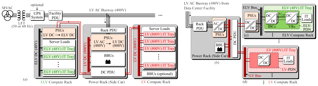
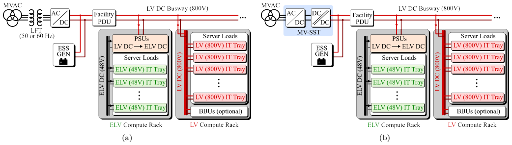
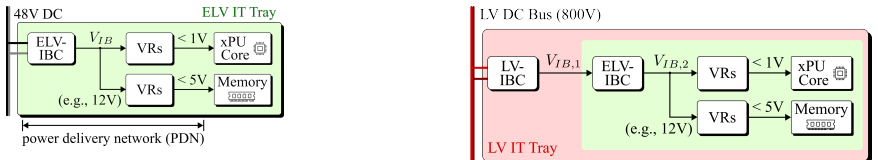
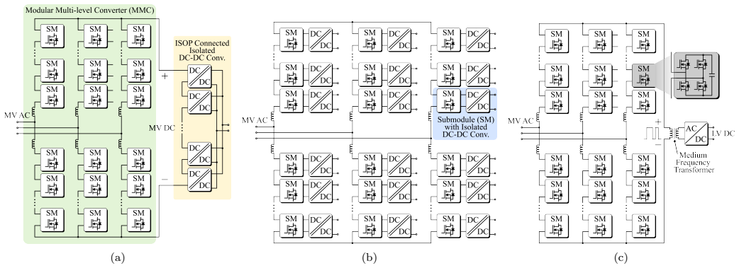
The paper states that rapid AI growth exposes fundamental limitations in existing power systems, requiring three stages of architectural shifts in data center power delivery supported by the building blocks of high-voltage conversion-ratio DC/DC converters, facility-level low-voltage DC distribution, and medium-voltage solid-state transformers.
What carries the argument
Three enabling technological building blocks: high-voltage conversion-ratio DC/DC converters, facility-level low-voltage DC distribution, and medium-voltage solid-state transformers.
If this is right
- Higher power densities become feasible in AI racks through improved conversion efficiency.
- Current transients are managed with reduced voltage drops and infrastructure stress.
- Thermal loads decrease, allowing denser compute packing without proportional cooling increases.
- Facility-wide distribution losses drop via higher voltage levels and DC paths.
- Grid interface stability improves through solid-state transformer capabilities.
Where Pith is reading between the lines
- The shifts could support continued scaling of large AI training clusters beyond current power ceilings.
- Adoption may drive broader standardization efforts for high-voltage DC safety protocols in facilities.
- Integration with on-site renewables becomes more practical due to DC-native distribution.
- Cost models for data center buildouts would need revision to account for new transformer and converter technologies.
Load-bearing premise
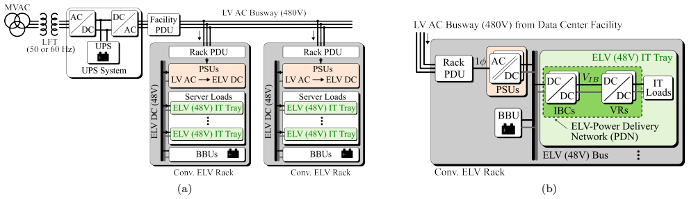
Traditional 48 V rack architectures, low-voltage AC distribution, and line-frequency transformer interfaces have fundamental limitations that AI power growth, transients, and thermal stress are exposing and that incremental fixes cannot resolve.
What would settle it
Sustained operation of existing 48 V and AC-based data center architectures at AI power densities well above current levels without efficiency collapse, excessive transients, or thermal failures would indicate the shifts are not required.
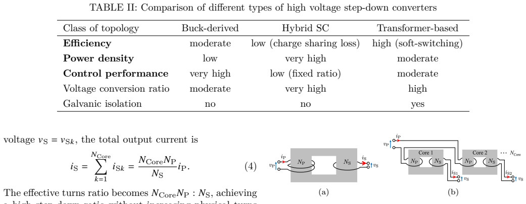
Figures

read the original abstract
The rapid growth of AI workloads is driving unprecedented increases in data center power demand, current transients, and thermal stress, exposing fundamental limitations in traditional 48 V rack architectures, low-voltage AC distribution, and line-frequency transformer interfaces. This paper reviews the three stages of architectural shifts required to support next-generation AI data centers and identifies three enabling technological building blocks: high-voltage conversion-ratio DC/DC converters, facility-level low-voltage DC distribution, and medium-voltage solid-state transformers. The advantages, technical challenges, and potential solutions associated with each building block are reviewed. Finally, future research directions and open challenges are discussed.
Editorial analysis
A structured set of objections, weighed in public.
Referee Report
Summary. The paper is a literature review that discusses the power delivery challenges posed by the rapid growth of AI workloads in data centers. It identifies fundamental limitations in traditional 48 V rack architectures, low-voltage AC distribution, and line-frequency transformer interfaces. The manuscript reviews three stages of architectural shifts and highlights three enabling technological building blocks: high-voltage conversion-ratio DC/DC converters, facility-level low-voltage DC distribution, and medium-voltage solid-state transformers. It examines the advantages, technical challenges, and potential solutions for each, and concludes with future research directions and open challenges.
Significance. This review synthesizes current literature on power architecture for AI data centers, providing a structured perspective on necessary shifts and key technologies. Given the increasing power demands of AI, such a survey could be valuable for guiding research in power electronics and data center infrastructure. The paper organizes existing work around specific building blocks, which may help in identifying research gaps without introducing new empirical results or derivations.
minor comments (2)
- [Abstract] Abstract: The abstract refers to 'three stages of architectural shifts' without naming or briefly describing them; adding this would better orient readers to the paper's structure.
- The mapping between the three stages and the three building blocks is not explicitly stated in the provided abstract or overview; clarifying this linkage in an early section would strengthen the central organizational claim.
Simulated Author's Rebuttal
We thank the referee for the positive assessment of our review paper and the recommendation for minor revision. No major comments were provided in the report, so we have no specific points requiring response or revision. We appreciate the recognition that the structured perspective on power architecture shifts and enabling technologies may help identify research gaps.
Circularity Check
No circularity; pure literature review with no derivations
full rationale
The manuscript is explicitly a review paper that organizes and summarizes existing literature on power-delivery architectures for AI data centers. It identifies three stages of shifts and three building-block technologies but introduces no new equations, quantitative predictions, fitted parameters, or derivations. The central claims are descriptive summaries of prior work; no load-bearing step reduces to self-definition, self-citation chains, or fitted inputs renamed as predictions. Therefore the document contains no circular reasoning by construction.
Axiom & Free-Parameter Ledger
Reference graph
Works this paper leans on
-
[1]
Data Center Growth and Grid Readiness,
IEEE Power & Energy Society, Industry Technical Support Leadership Committee (ITSLC), Task Force on Data Center Growth and Grid Readiness, “Data Center Growth and Grid Readiness,” IEEE Power & Energy Society, Piscataway, NJ, USA, Technical Report PES-TR 131, May 2025, Prepared by the Industry Technical Support Leadership Committee (ITSLC) Task Force on Da...
2025
-
[2]
Data cen- ter power and energy management: Past, present, and future,
R. Bianchini, C. Belady, and A. Sivasubramaniam, “Data cen- ter power and energy management: Past, present, and future,” IEEE Micro, vol. 44, no. 5, pp. 30–36, 2024
2024
-
[3]
Design of ion-implanted mosfet’s with very small physical dimensions,
R. Dennard, F. Gaensslen, H.-N. Yu, V. Rideout, E. Bassous, and A. LeBlanc, “Design of ion-implanted mosfet’s with very small physical dimensions,”IEEE Journal of Solid-State Cir- cuits, vol. 9, no. 5, pp. 256–268, 1974
1974
-
[4]
800 vdc architecture for next- generation ai infrastructure: The architectural imperative of 800 vdc and integrated energy storage,
J. Huntington and M. Tu, “800 vdc architecture for next- generation ai infrastructure: The architectural imperative of 800 vdc and integrated energy storage,” NVIDIA Corporation, White Paper, January 2025,©2025 NVIDIA Corporation. All rights reserved. [Online]. Available: https://nvdam.nvidia. com/assets/share/asset/zlg5snufeo
2025
-
[5]
2024 united states data center energy usage re- port,
A. Shehabi, S. J. Smith, A. Hubbard, A. Newkirk, N. Lei, M. A. B. Siddik, B. Holecek, J. Koomey, E. Masanet, and D. Sartor, “2024 united states data center energy usage re- port,” Lawrence Berkeley National Laboratory, Berkeley, CA, USA, Tech. Rep. LBNL-2001637, Dec. 2024
2024
-
[6]
Ai-driven data center energy profile, power quality, sustainable sitting, and energy management: A comprehensive survey,
R. R. Ahrabi, A. Mousavi, E. Mohammadi, R. Wu, and A. K. Chen, “Ai-driven data center energy profile, power quality, sustainable sitting, and energy management: A comprehensive survey,”in2025IEEEConferenceonTechnologiesforSustain- ability (SusTech), 2025, pp. 1–8
2025
-
[7]
Opti- mal energy management of data center micro-grid considering computing workloads shift,
L. Liu, X. Shen, Z. Chen, Q. Sun, and R. Wennersten, “Opti- mal energy management of data center micro-grid considering computing workloads shift,”IEEEAccess, vol. 12, pp. 102061– 102075, 2024
2024
-
[8]
Event driven power consumption op- timization control model of gpu clusters,
H. Wang and Y. Cao, “Event driven power consumption op- timization control model of gpu clusters,”Cluster Computing, vol. 22, pp. 965–979, 2019
2019
-
[9]
Enabling 1 mw it racks and liquid cooling at ocp emea summit,
Google Cloud, “Enabling 1 mw it racks and liquid cooling at ocp emea summit,” https://cloud.google.com/blog/topics/systems/ enabling-1-mw-it-racks-and-liquid-cooling-at-ocp-emea-summit, 2025, accessed: 2025-12-09
2025
-
[10]
Diablo 400 project: Rack and power, base specification (version 0.5.2),
“Diablo 400 project: Rack and power, base specification (version 0.5.2),” https://www.opencompute.org/documents/ ocp-specification-diablo-400-v0p5p2-2025-05-30-pdf, Open Compute Project, 2025, accessed: 2026-03-17
2025
-
[11]
Advanced datacenter ac/dc distribution and conversion power architecture,
B. McDonald, N. Cai, K. G. Ravikumar, E. Nasr, J. Wang, and R. Nagimov, “Advanced datacenter ac/dc distribution and conversion power architecture,” Presentation slides, OCP Global Summit, San Jose, California, October 2025. [Online]. Available: https://drive.google.com/file/d/12ANi1tlYSSQ6_ ileeeM3e2avrRQtrDes/view
2025
-
[12]
Dc microgrid protection: A comprehen- sive review,
S. Beheshtaein, R. M. Cuzner, M. Forouzesh, M. Savaghebi, and J. M. Guerrero, “Dc microgrid protection: A comprehen- sive review,”IEEE Journal of Emerging and Selected Topics in Power Electronics, pp. 1–1, 2019
2019
-
[13]
Google 48v update: Flatbed and stc,
S. McCauley and S. Jiang, “Google 48v update: Flatbed and stc,” 2018, Accessed on: August 27, 2025. [Online]. Available: https://www.opencompute.org/files/ External-2018-OCP-Summit-Google-48V-Update-Flatbed-and-STC-20180321. pdf
2018
-
[14]
Data center circuit protection — application note 10079,
E. Corporation, “Data center circuit protection — application note 10079,” Eaton Corporation, Bussmann Division, Moon Township, PA, USA, Tech. Rep., July
-
[15]
Available: https://www.eaton.com/content/ dam/eaton/products/electrical-circuit-protection/fuses/ technical-literature/bus-ele-an-10079-data-centers.pdf
[Online]. Available: https://www.eaton.com/content/ dam/eaton/products/electrical-circuit-protection/fuses/ technical-literature/bus-ele-an-10079-data-centers.pdf
-
[16]
Electrical distribution equipment in data center environments (white paper 61, revision 2),
P. Hu, “Electrical distribution equipment in data center environments (white paper 61, revision 2),” Schneider Electric, Rueil-Malmaison, France / Boston, MA, USA, Tech. Rep., July 2019. [Online]. Available: https://download.schneider-electric.com/files?p_Doc_ Ref=SPD_VAVR-8W4MEX_EN&p_enDocType=White+ Paper&p_File_Name=VAVR-8W4MEX_R2_EN.pdf
2019
-
[17]
Open rack standard V2.0,
O. C. P. Foundation, “Open rack standard V2.0,” Open Compute Project Foundation, Menlo Park, CA, USA, Tech. Rep., January 2017, available online. [On- line]. Available: https://www.opencompute.org/documents/ openrack-standard-v20-overview
2017
-
[18]
Power stabilization for ai training datacenters,
E. Choukse, B. Warrier, S. Heath, L. Belmont, A. Zhao, H. A. Khan, B. Harry, M. Kappel, R. J. Hewett, K. Datta, Y. Pei, C. Lichtenberger, J. Siegler, D. Lukofsky, Z. Kahn, G. Sahota, A. Sullivan, C. Frederick, H. Thai, R. Naughton, D. Jurnove, J. Harp, R. Carper, N. Mahalingam, S. Varkala, A. G. Kumbhare, S. Desai, V. Ramamurthy, P. Gottumukkala, G. Bhati...
arXiv 2025
-
[19]
Open rack v2.1 standard compliant 48v system design hi gh efficiency power and lithium bbu units,
P. Fernandez, “Open rack v2.1 standard compliant 48v system design hi gh efficiency power and lithium bbu units,” 2018, Accessed on: August 27, 2025.[Online].Available:https://www.opencompute.org/files/ OCP18-Workshop-Huawei-v2-final.pdf
2018
-
[20]
High current, high power-density intermediate bus converters for vertical power delivery to next- generationprocessors,
P. R. Prakash, A. Nabih, Y. Liang, S. Kudva, M. Mosa, C. T. Gray, and Q. Li, “High current, high power-density intermediate bus converters for vertical power delivery to next- generationprocessors,”IEEETransactionsonPowerElectron- ics, vol. 40, no. 10, pp. 14771–14784, 2025
2025
-
[21]
Potential power solutions for gigawatt data centers for ai training (grid to chip),
R. Pieper, “Potential power solutions for gigawatt data centers for ai training (grid to chip),” 2024, Accessed on: August 27, 2025. [Online]. Available: https://www.nvidia.com/en-us/ on-demand/session/gtc24-s62987/
2024
-
[22]
Phase shift regulated resonant switched-capacitor-based intermediate bus converter for 48 v data center power system,
J. Liang, Y. Qin, Y. Liu, M. Fu, and H. Wang, “Phase shift regulated resonant switched-capacitor-based intermediate bus converter for 48 v data center power system,”IEEE Transac- tions on Industrial Electronics, vol. 72, no. 2, pp. 1475–1485, 2025
2025
-
[23]
Design considerations for 48-v vrm: Architecture, magnetics, and per- formance tradeoffs,
M. Chen, S. Jiang, J. A. Cobos, and B. Lehman, “Design considerations for 48-v vrm: Architecture, magnetics, and per- formance tradeoffs,” in2023 Fourth International Symposium on 3D Power Electronics Integration and Manufacturing (3D- PEIM), 2023, pp. 1–9
2023
-
[24]
Switched tank converters,
S. Jiang, S. Saggini, C. Nan, X. Li, C. Chung, and M. Yazdani, “Switched tank converters,”IEEE Transactions on Power Electronics, vol. 34, no. 6, pp. 5048–5062, 2019
2019
-
[25]
Overview of voltage regulator modules in 48 v bus-based data center power systems,
J. Liang, L. Wang, M. Fu, J. Liang, and H. Wang, “Overview of voltage regulator modules in 48 v bus-based data center power systems,”CPSS Transactions on Power Electronics and Applications, vol. 7, no. 3, pp. 283–299, 2022
2022
-
[26]
Op- timization of high-density and high-efficiency switched-tank converter for data center applications,
X. Lyu, Y. Li, N. Ren, C. Nan, D. Cao, and S. Jiang, “Op- timization of high-density and high-efficiency switched-tank converter for data center applications,”IEEE Transactions on Industrial Electronics, vol. 67, no. 2, pp. 1626–1637, 2020
2020
-
[27]
A review of immediate bus architecture: A system perspective,
D. F. D. Tan, “A review of immediate bus architecture: A system perspective,”IEEE Journal of Emerging and Selected Topics in Power Electronics, vol. 2, no. 3, pp. 363–373, 2014
2014
-
[28]
Power delivery trade- offs when preparing for the next wave of ai comput- ing growth,
Texas Instruments, Incorporated, “Power delivery trade- offs when preparing for the next wave of ai comput- ing growth,” https://www.ti.com/document-viewer/lit/html/ SSZTDB1, Texas Instruments, October 2025, technical article; accessed 2026-01-21
2025
-
[30]
1 mhz 48–12 v regulated dcx with single transformer,
T. Liu, X. Wu, and S. Yang, “1 mhz 48–12 v regulated dcx with single transformer,”IEEE Journal of Emerging and Selected Topics in Power Electronics, vol. 9, no. 1, pp. 38–47, 2021
2021
-
[31]
Investiga- tion of candidate vrm topologies for future microprocessors,
X. Zhou, P.-L. Wong, P. Xu, F. Lee, and A. Huang, “Investiga- tion of candidate vrm topologies for future microprocessors,” IEEE Transactions on Power Electronics, vol. 15, no. 6, pp. 1172–1182, 2000
2000
-
[32]
A discussion on ultrahigh efficiency and ultrahigh power density dc–dc converter technologies,
Y.-F. Liu and D. Tan, “A discussion on ultrahigh efficiency and ultrahigh power density dc–dc converter technologies,”IEEE Journal of Emerging and Selected Topics in Power Electronics, vol. 11, no. 3, pp. 2457–2468, 2023
2023
-
[33]
A switched-capacitor and series-resonant hybrid mhz dcx in data centerapplications,
J. Liang, L. Wang, J. Liang, M. Fu, T. Long, and H. Wang, “A switched-capacitor and series-resonant hybrid mhz dcx in data centerapplications,”IEEETransactionsonPowerElectronics, vol. 39, no. 10, pp. 13389–13400, 2024
2024
-
[34]
Virtual intermediate bus cpu voltage regulator,
Y. Chen, P. Wang, H. Cheng, G. Szczeszynski, S. Allen, D. M. Giuliano, and M. Chen, “Virtual intermediate bus cpu voltage regulator,”IEEE Transactions on Power Electronics, vol. 37, no. 6, pp. 6883–6898, 2022
2022
-
[35]
Three-dimensional interconnect llc-dcx converter fordatacenterapplication,
P.Wang,B.N.Sanusi,T.-G.Zsurzsan,M.A.E.Andersen,and Z. Ouyang, “Three-dimensional interconnect llc-dcx converter fordatacenterapplication,”IEEETransactionsonPowerElec- tronics, vol. 40, no. 10, pp. 15306–15315, 2025
2025
-
[36]
W. C. Liu, Z. Ye, and R. C. Pilawa-Podgurski, “A 97
-
[37]
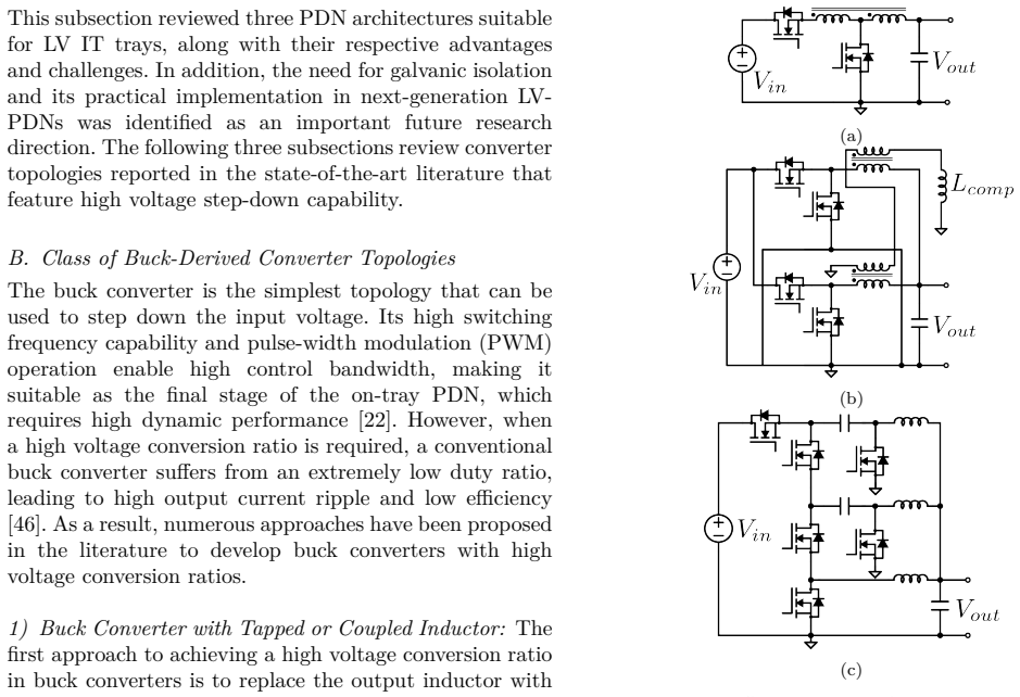
An interleaved series-capacitor tapped buck converter for high step-down dc/dc application,
L. Zhang and S. Chakraborty, “An interleaved series-capacitor tapped buck converter for high step-down dc/dc application,” IEEE Transactions on Power Electronics, vol. 34, no. 7, pp. 6565–6574, 2019
2019
-
[38]
Review of high-frequency high-voltage-conversion-ratio dc–dc convert- ers,
Y. Guan, C. Cecati, J. M. Alonso, and Z. Zhang, “Review of high-frequency high-voltage-conversion-ratio dc–dc convert- ers,”IEEE Journal of Emerging and Selected Topics in Indus- trial Electronics, vol. 2, no. 4, pp. 374–389, 2021
2021
-
[39]
Increasing hyperscale data center efficiency: A better way to manage 54-v48-v-to-point-of-load direct conver- sion,
P. Sandri, “Increasing hyperscale data center efficiency: A better way to manage 54-v48-v-to-point-of-load direct conver- sion,”IEEE Power Electronics Magazine, vol. 4, no. 4, pp. 58– 64, 2017
2017
-
[40]
Vr12.0 voltage regulator specification and 48 v power architecture white paper,
Mouser Electronics, “Vr12.0 voltage regulator specification and 48 v power architecture white paper,” Mouser Electronics, White Paper, 2012, accessed: 2026-02-03. [Online]. Available: https://www.mouser.com/pdfdocs/wp_VR12.pdf
2012
-
[41]
Direct 48-/1-v gan-based dc–dc power converter with double step-down architecture and master–slave ao2t control,
D. Yan, X. Ke, and D. B. Ma, “Direct 48-/1-v gan-based dc–dc power converter with double step-down architecture and master–slave ao2t control,”IEEE Journal of Solid-State Circuits, vol. 55, no. 4, pp. 988–998, 2020
2020
-
[42]
M. Gong, H. Chen, X. Zhang, R. Jain, and A. Raychowdhury, “A 90.4
-
[43]
Optimum number of cascaded cells for high-power medium-voltage ac–dc converters,
J. E. Huber and J. W. Kolar, “Optimum number of cascaded cells for high-power medium-voltage ac–dc converters,”IEEE Journal of Emerging and Selected Topics in Power Electronics, vol. 5, no. 1, pp. 213–232, 2017
2017
-
[44]
Y. Li, X. Lyu, D. Cao, S. Jiang, and C. Nan, “A 98.55
-
[45]
A comparative study of switched-tank converter and cascaded voltage divider for 48-v data center application,
X. Lyu, Y. Li, N. Ren, S. Jiang, and D. Cao, “A comparative study of switched-tank converter and cascaded voltage divider for 48-v data center application,”IEEE Journal of Emerging and Selected Topics in Power Electronics, vol. 8, no. 2, pp. 1547–1559, 2020
2020
-
[46]
Single-stage high- efficiency 48/1 v sigma converter with integrated magnetics,
M. H. Ahmed, C. Fei, F. C. Lee, and Q. Li, “Single-stage high- efficiency 48/1 v sigma converter with integrated magnetics,” IEEETransactionsonIndustrialElectronics, vol. 67, no. 1, pp. 192–202, 2020
2020
-
[47]
A coupled inductor- based high step-down/ step-up dc-dc nonisolated bidirectional converter with reduced ripple in current and voltage stress,
M. Biswas, H.-C. Kim, and J.-W. Park, “A coupled inductor- based high step-down/ step-up dc-dc nonisolated bidirectional converter with reduced ripple in current and voltage stress,” IEEE Journal of Emerging and Selected Topics in Power Electronics, vol. 12, no. 4, pp. 3574–3587, 2024
2024
-
[49]
Unifiedsynthesisoftapped-inductordc-to-dc converters,
B.W. Williams, “Unifiedsynthesisoftapped-inductordc-to-dc converters,”IEEE Transactions on Power Electronics, vol. 29, no. 10, pp. 5370–5383, 2014
2014
-
[50]
Analysis and implementation of a novel bidirectional dc–dc converter,
L.-S. Yang and T.-J. Liang, “Analysis and implementation of a novel bidirectional dc–dc converter,”IEEE Transactions on Industrial Electronics, vol. 59, no. 1, pp. 422–434, 2012
2012
-
[51]
Static and dynamic modeling of tapped-inductor dc-to-dc converters,
M. Rico, J. Uceda, J. Sebastian, and F. Aldana, “Static and dynamic modeling of tapped-inductor dc-to-dc converters,” in 1987IEEEPowerElectronicsSpecialistsConference,1987,pp. 281–288
1987
-
[52]
Tapped-inductor buck converter for high-step-down dc-dc conversion,
K. Yao, M. Ye, M. Xu, and F. Lee, “Tapped-inductor buck converter for high-step-down dc-dc conversion,”IEEE Trans- actions on Power Electronics, vol. 20, no. 4, pp. 775–780, 2005
2005
-
[53]
Com- parison of a buck converter and a series capacitor buck con- verter for high-frequency, high-conversion-ratio voltage regula- tors,
P. S. Shenoy, M. Amaro, J. Morroni, and D. Freeman, “Com- parison of a buck converter and a series capacitor buck con- verter for high-frequency, high-conversion-ratio voltage regula- tors,”IEEETransactionsonPowerElectronics,vol.31,no.10, pp. 7006–7015, 2016
2016
-
[54]
Native and emulated transinductor volt- age regulator with constant on-time current control and phase nonoverlapping–discrete-time modeling and dynamic perfor- mance investigation,
R. Yang and S. Tian, “Native and emulated transinductor volt- age regulator with constant on-time current control and phase nonoverlapping–discrete-time modeling and dynamic perfor- mance investigation,”IEEE Transactions on Power Electron- ics, vol. 41, no. 4, pp. 5588–5601, 2026
2026
-
[55]
Animprovedhybrid-coupledinduc- tor structure with flux reduction and integrated controllable coupling function,
F.Zhu,X.Lou,andQ.Li,“Animprovedhybrid-coupledinduc- tor structure with flux reduction and integrated controllable coupling function,”IEEE Transactions on Power Electronics, vol. 39, no. 1, pp. 1103–1114, 2024
2024
-
[56]
Coupled inductors with an adaptive coupling coefficient for multiphase voltage regulators,
F. Zhu and Q. Li, “Coupled inductors with an adaptive coupling coefficient for multiphase voltage regulators,”IEEE Transactions on Power Electronics, vol. 38, no. 1, pp. 739–749, 2023
2023
-
[57]
Reconfigurable trans-inductor voltage regulator with improved light load efficiency in data center applications,
Z. Wang, Z. Li, and H. Wang, “Reconfigurable trans-inductor voltage regulator with improved light load efficiency in data center applications,” in2025 IEEE Applied Power Electronics Conference and Exposition (APEC), 2025, pp. 485–490
2025
-
[58]
Analysis of double step-down two-phase buck con- verter for vrm,
K. Nishijima, K. Harada, T. Nakano, T. Nabeshima, and T. Sato, “Analysis of double step-down two-phase buck con- verter for vrm,” inINTELEC 05 - Twenty-Seventh Interna- tional Telecommunications Conference, 2005, pp. 497–502
2005
-
[59]
Multiphase buck con- verters with extended duty cycle,
Y. Jang, M. Jovanovic, and Y. Panov, “Multiphase buck con- verters with extended duty cycle,” inTwenty-First Annual IEEE Applied Power Electronics Conference and Exposition,
-
[60]
APEC ’06., 2006, pp. 7 pp.–
2006
-
[61]
A novel three-phase buck converter with boot- strap driver circuit,
K. Abe, K. Nishijima, K. Harada, T. Nakano, T. Nabeshima, and T. Sato, “A novel three-phase buck converter with boot- strap driver circuit,” in2007 IEEE Power Electronics Special- ists Conference, 2007, pp. 1864–1871
2007
-
[62]
C. Xue, B. Gong, H. Xu, Y. Yu, Y. Ding, W. Li, and W. Qu, “A 36–55 v input 0.6–2.5 v output bypass-assist series-capacitor power converter with 93.1
-
[63]
Analysis and design of a nonisolated high step-down converter with coupled inductor and zvs operation,
C. Wei, Y. Zhao, Y. Zheng, L. Xie, and K. M. Smedley, “Analysis and design of a nonisolated high step-down converter with coupled inductor and zvs operation,”IEEE Transactions on Industrial Electronics, vol. 69, no. 9, pp. 9007–9018, 2022
2022
-
[64]
High step-down noniso- lated dc–dc converter with coupled inductors,
M. Rezvanyvardom and A. Mirzaei, “High step-down noniso- lated dc–dc converter with coupled inductors,”IEEE Journal of Emerging and Selected Topics in Power Electronics, vol. 9, no. 3, pp. 3353–3360, 2021
2021
-
[65]
High gain and high-efficiency bidirectional dc–dc converter with current shar- ingcharacteristicsusingcoupledinductor,
S. B. Santra, D. Chatterjee, and T.-J. Liang, “High gain and high-efficiency bidirectional dc–dc converter with current shar- ingcharacteristicsusingcoupledinductor,”IEEETransactions on Power Electronics, vol. 36, no. 11, pp. 12819–12833, 2021
2021
-
[66]
Voltage regulator optimization using multiwinding coupled inductors and extended duty ra- tio mechanisms,
B. S. Oraw and R. Ayyanar, “Voltage regulator optimization using multiwinding coupled inductors and extended duty ra- tio mechanisms,”IEEE Transactions on Power Electronics, vol. 24, no. 6, pp. 1494–1505, 2009
2009
-
[67]
A two-phase high step down coupled-inductor converter for next generation low voltage cpu,
K. Matsumoto, K. Nishijima, T. Sato, and T. Nabeshima, “A two-phase high step down coupled-inductor converter for next generation low voltage cpu,” in8th International Conference on Power Electronics - ECCE Asia, 2011, pp. 2813–2818
2011
-
[68]
Analysis and design of ultrafast series capacitor trans-inductor voltage regulator with constant on-time control,
L. Wang, C. Li, J. Liang, W. T. Ng, and H. Wang, “Analysis and design of ultrafast series capacitor trans-inductor voltage regulator with constant on-time control,”IEEE Transactions on Power Electronics, vol. 40, no. 6, pp. 8315–8327, 2025
2025
-
[69]
Model- ing and comparison of passive component volume of hybrid resonant switched-capacitor converters,
Z. Ye, S. R. Sanders, and R. C. N. Pilawa-Podgurski, “Model- ing and comparison of passive component volume of hybrid resonant switched-capacitor converters,”IEEE Transactions on Power Electronics, vol. 37, no. 9, pp. 10903–10919, 2022
2022
-
[70]
Quantifying charge sharing loss in switched capacitor invert- ers for capacitive power transfer applications,
C.S.Johnson,T.Marcrum,M.Tidwell,W.Stump,M.Coultis, M. Pearce, C. W. Van Neste, D. Boyd, and C. Vaughan, “Quantifying charge sharing loss in switched capacitor invert- ers for capacitive power transfer applications,”IEEE Journal of Emerging and Selected Topics in Power Electronics, vol. 13, no. 1, pp. 1330–1338, 2025
2025
-
[71]
Mergedtwo-stagepowerconverterarchitecturewithsoftcharg- ing switched-capacitor energy transfer,
R. C. Pilawa-Podgurski, D. M. Giuliano, and D. J. Perreault, “Mergedtwo-stagepowerconverterarchitecturewithsoftcharg- ing switched-capacitor energy transfer,” in2008 IEEE Power Electronics Specialists Conference, 2008
2008
-
[72]
Merged two- stage power converter with soft charging switched-capacitor stage in 180 nm cmos,
R. C. N. Pilawa-Podgurski and D. J. Perreault, “Merged two- stage power converter with soft charging switched-capacitor stage in 180 nm cmos,”IEEE Journal of Solid-State Circuits, vol. 47, no. 7, pp. 1557–1567, 2012
2012
-
[73]
A general method for analyzing resonant and soft-charging operation of switched- capacitor converters,
Y. Lei and R. C. N. Pilawa-Podgurski, “A general method for analyzing resonant and soft-charging operation of switched- capacitor converters,”IEEE Transactions on Power Electron- ics, vol. 30, no. 10, pp. 5650–5664, 2015
2015
-
[74]
The cascaded resonant converter: A hybrid switched-capacitor topology with high power density and efficiency,
Z. Ye, Y. Lei, and R. C. N. Pilawa-Podgurski, “The cascaded resonant converter: A hybrid switched-capacitor topology with high power density and efficiency,”IEEE Transactions on Power Electronics, vol. 35, no. 5, pp. 4946–4958, 2020
2020
-
[75]
Split-phase con- trol: Achieving complete soft-charging operation of a dickson switched-capacitor converter,
Y. Lei, R. May, and R. Pilawa-Podgurski, “Split-phase con- trol: Achieving complete soft-charging operation of a dickson switched-capacitor converter,”IEEE Transactions on Power Electronics, vol. 31, no. 1, pp. 770–782, 2016
2016
-
[76]
Resonant- switched capacitor converters for chip-scale power delivery: Design and implementation,
K. Kesarwani, R. Sangwan, and J. T. Stauth, “Resonant- switched capacitor converters for chip-scale power delivery: Design and implementation,”IEEE Transactions on Power Electronics, vol. 30, no. 12, pp. 6966–6977, 2015
2015
-
[77]
High power res- onant switched-capacitor step-down converter,
O. Keiser, P. K. Steimer, and J. W. Kolar, “High power res- onant switched-capacitor step-down converter,” in2008 IEEE PowerElectronicsSpecialistsConference,2008,pp.2772–2777
2008
-
[78]
A modular resonant dc–dc converter with high step-down ratio for tapping power from hvdc systems,
E. C. Mathew, R. Sharma, and A. Das, “A modular resonant dc–dc converter with high step-down ratio for tapping power from hvdc systems,”IEEE Transactions on Industrial Elec- tronics, vol. 68, no. 1, pp. 324–332, 2021
2021
-
[79]
Hybrid resonant switched-capacitor converter for 48–3.4 v direct conversion,
A. Dago, M. Leoncini, S. Saggini, S. Levantino, and M. Ghioni, “Hybrid resonant switched-capacitor converter for 48–3.4 v direct conversion,”IEEE Transactions on Power Electronics, vol. 37, no. 11, pp. 12998–13002, 2022
2022
-
[80]
Resonant and multi-mode operation of flying capacitor multi-level dc-dc converters,
K. Kesarwani and J. T. Stauth, “Resonant and multi-mode operation of flying capacitor multi-level dc-dc converters,” in 2015 IEEE 16th Workshop on Control and Modeling for Power Electronics (COMPEL), 2015, pp. 1–8
2015
-
[81]
Zero-current-switching multilevel modular switched-capacitor dc–dc converter,
D. Cao and F. Z. Peng, “Zero-current-switching multilevel modular switched-capacitor dc–dc converter,”IEEE Transac- tions on Industry Applications, vol. 46, no. 6, 2010
2010
-
[82]
Multilevel modu- lar switched-capacitor resonant converter with voltage regula- tion,
Y. Li, B. Curuvija, X. Lyu, and D. Cao, “Multilevel modu- lar switched-capacitor resonant converter with voltage regula- tion,” in2017IEEEAppliedPowerElectronicsConferenceand Exposition (APEC), 2017, pp. 88–93
2017
discussion (0)
Sign in with ORCID, Apple, or X to comment. Anyone can read and Pith papers without signing in.