REVIEW 3 major objections 5 minor 35 references
Global cracking elements: a novel tool for Galerkin-based approaches simulating quasi-brittle fracture
T0 review · 3 major / 5 minor · reviewed 2026-08-14 · deepseek-v4-flash
Pith's one-line read The paper claims a Galerkin finite-element method that reuses the center-node degrees of freedom of a nine-node quadrilateral element as global crack openings, eliminating remeshing, enrichment, and crack tracking in quasi-brittle fracture.
desk verdict Neat pseudo-Q9 DOF-borrowing reformulation of CEM with credible benchmarks, but the tangent symmetrization in Eq. 16 is unjustified—possibly inconsistent—and the efficiency claim is under-supported. read the letter →
The pith
A machine-rendered reading of the paper's core claim, the machinery that carries it, and where it could break.
The reading
What carries the argument
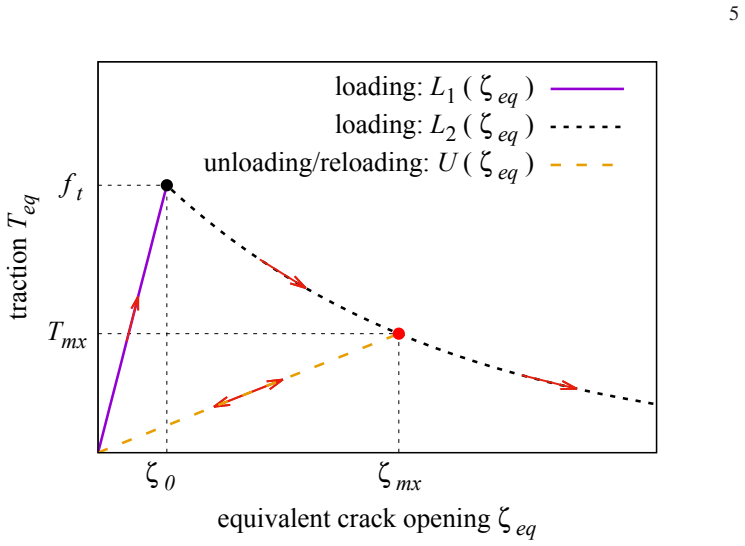
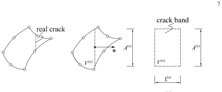
The load-bearing object is the pseudo-Q9 cracking element, a strong-discontinuity embedded formulation in which each crack is represented by a displacement jump inside an element rather than by additional nodes. In it, the center-node degrees of freedom of a standard nine-node quadrilateral are borrowed, not deleted: they switch from describing the displacement of the center point to describing the normal and tangential crack openings ($\zeta_n$, $\zeta_t$) of that element. This promotion of crack openings to global unknowns is what removes the inner element-level iteration of the original CEM and yields a symmetric, sparse global stiffness matrix. The element's strain is written as $\bar{\varepsilon} = B U - B_\zeta \zeta$ (with $B_\zeta$ built from the crack normal $\mathbf{n}$ and the characteristic length $l_c$), and the practical stiffness is the symmetrized form $K_{\mathrm{sym}}$ assembled from $[B, B_\zeta]$, with the traction-separation tangent added in the crack-opening block. That symmetrized matrix carries the Newton-Raphson iteration in the numerical examples.
What would settle it
A direct check would be to run the method on a few-element specimen under non-proportional loading (load, unload, then rotate the principal stress direction) and compare the Newton iteration counts and final crack openings with those obtained from the non-symmetric tangent version of the same element; if the symmetric version needs significantly more iterations or diverges, the central stability claim is not general.
Extended reading notes
Core claim
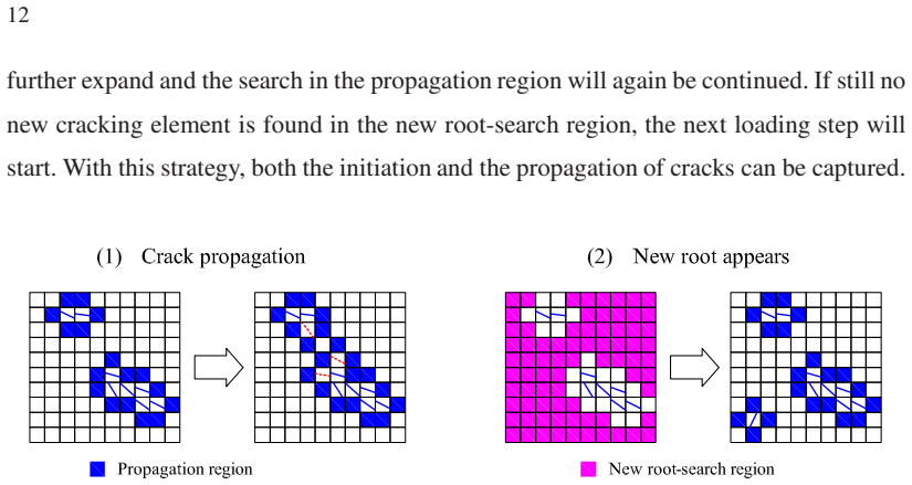
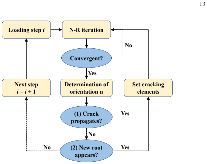
The central claim is that a strong-discontinuity embedded approach to quasi-brittle fracture can be written so that the only extra unknowns are global, element-wise crack openings, and that this form is more robust and cheaper than its predecessor. The device is a 'pseudo-Q9' element: the perimeter nodes of a nine-node quadrilateral keep their displacement unknowns, and the center node's two displacement degrees of freedom are replaced by the normal and tangential crack openings $\zeta_n$ and $\zeta_t$ of that element. From then on the cracked element is an ordinary Galerkin finite element with a symmetric, sparse stiffness matrix, so no remeshing, enriched basis, or crack-tracking strategy is required. Crack orientation is chosen locally from the eigenvector of the strain, and propagation is found by expanding a propagation region rather than by following a crack tip. The numerical tests show the method reproducing the benchmark force-displacement curves and peak loads of the L-shaped panel and slotted Brazilian disks, with small mesh dependence and fewer Newton iterations than the CEM.
Load-bearing premise
The method's stability and speed depend on an unproved simplification in which a non-symmetric matrix is replaced by a symmetric one in the element formulation; if that simplification is inaccurate for some loading paths, the claimed Newton-Raphson advantages may disappear.
Editorial extensions
If this is right
- Crack initiation and propagation in quasi-brittle materials can be simulated with no remeshing, no enrichment, and no crack-tracking strategy, using only standard Galerkin finite-element machinery and irregular meshes.
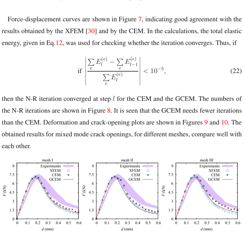
- Because crack openings are global unknowns, the Newton-Raphson iteration needs fewer steps than in the original CEM; the paper reports this consistently across the benchmark meshes.
- The pseudo-Q9 form keeps a symmetric sparse stiffness matrix, so existing sparse linear solvers and standard nonlinear finite-element codes can adopt the method without new global data structures.
- The formulation can be changed to an enriched form of the crack-opening field when desired, since the pseudo-Q9 structure leaves a clear place for enrichment.
- Presently only quadrilateral elements with nonlinear displacement interpolation are usable, so the method is not yet available for triangular or linear-element meshes.
Reading between the lines
- Beyond the paper, the center-node borrowing suggests a general recipe: any element with re-assignable degrees of freedom could carry kinematic enrichment inside a standard Galerkin code, so the idea may extend to shear bands or delamination without changing the global solver.
- Beyond the paper, the loading paths shown are monotonically increasing, so an untested consequence is how the symmetric-tangent replacement behaves under unloading-reloading cycles or load-path rotations; those are exactly the situations where a non-symmetric tangent may matter.
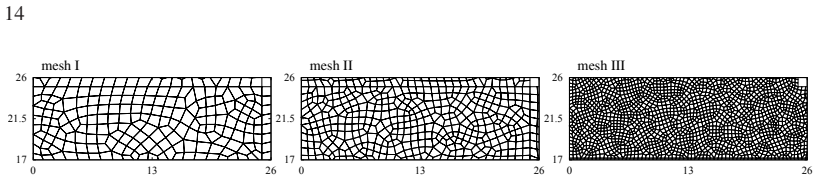
- Beyond the paper, a quantitative mesh-convergence study across several element sizes, rather than the two meshes shown, would pin down the claimed negligible mesh dependency.
Signed reviews
Editorial analysis
A structured set of objections, weighed in public.
Referee Report
Summary. The paper proposes the Global Cracking Elements Method (GCEM), a reformulation of the Cracking Elements Method (CEM) for quasi-brittle fracture. The key idea is to treat element-wise crack openings as global unknowns by borrowing the degrees of freedom of the center node of a Q9 element, thereby producing a pseudo-Q9 formulation that fits the standard Galerkin/FEM assembly framework. The kinematics, mixed-mode traction-separation law, and crack-initiation/propagation criteria are adopted from the authors' previous CEM publications. The new element is presented in matrix form, and numerical tests include an L-shaped panel and Brazilian disk tests with single and double slots, compared with experiments, XFEM, CEM, phase-field, and peridynamics results. The reported advantages are no remeshing, no enrichment, no crack tracking, and fewer Newton iterations than the original CEM.
Significance. If the formulation is fully justified, GCEM is a potentially attractive method for quasi-brittle fracture: the center-node borrowing idea is elegant, the implementation appears straightforward, the benchmark results match independent solutions and experiments, and the mesh-sensitivity evidence is favorable. The paper is also honest about current limitations, namely quadrilateral elements only and no direct crack-tip tracking. However, the central numerical claim, improved stability and efficiency over CEM, currently rests on an unproved replacement of the consistent tangent by a symmetric matrix, and the internal consistency of the tangent derivation is questionable. Thus the significance is conditional on resolving the tangent issue and on providing a more quantitative cost comparison.
major comments (3)
- [Section 2.3, Eq. (16)] The paper replaces K_s,new from Eq. (15) with the symmetric matrix K_sym in Eq. (16) with only the statement 'Fortunately, K_s,new can be replaced by the following symmetric matrix.' No derivation from the residual, no proof of solution invariance, and no convergence study are provided. This replacement is load-bearing because the Newton-Raphson iteration and the claimed efficiency and stability advantage in Section 3 (Figs. 7-8) depend on it. Please add a proof that K_sym corresponds to a consistent tangent or an equivalent potential, and a numerical study comparing convergence behavior and solutions obtained with K_sym against those obtained with the unsymmetric tangent.
- [Section 2.3, Eqs. (14)-(15)] The statement that K_s,new is not symmetric is inconsistent with the quadrature implied by the formulation. With B^(e),1 evaluated at the center point and B_zeta constant, the off-diagonal blocks of K_new in Eq. (15) are transposes of each other, and the added diagonal block is symmetric, so K_s,new as printed is symmetric. If the intended matrix is instead the one in Eq. (14) with the lower-left block scaled by -l_c, then K_sym in Eq. (16) is not the linearization of the residual. Please clarify which matrix is actually assembled and resolve this sign and symmetry inconsistency; the current text leaves the reader unable to reproduce the tangent.
- [Section 3, Figs. 7-8] The efficiency claim is supported only by Newton-iteration counts for the L-shaped panel, not by wall-clock time and not by comparison with a solver that handles the unsymmetric tangent. Because GCEM moves the crack-opening unknowns into the global system, its per-iteration cost may be higher than CEM's element-level condensation. Please provide a cost comparison such as CPU time or total linear solves, or restrict the claim to iteration counts.
minor comments (5)
- [Section 2.1, Eq. (2)] The threshold fracture energy is fixed as Gf,0 = 0.001 Gf without comment or sensitivity study; since this parameter enters the initial stiffness and the tangent matrix D, please state the basis for this value and its influence on the reported results.
- [Section 3.1, Eq. (22)] There is a typo 'if if' before the convergence criterion; please also specify how the criterion is applied when the total elastic energy becomes small or changes sign.
- [Section 2.4, Eq. (18)] The crack-orientation criterion is adopted from [1]; it would be helpful to state explicitly whether n^(e) is updated during Newton iterations for an already-cracked element and to quantify the claim that the rotation of n^(e) is very small.
- [Section 4] The sentence 'Unlike methods based on equivalent-type theories. The GCEM does not introduce bonds/lattices/links...' is grammatically incomplete and should be rewritten.
- [General] The paper would benefit from a short derivation showing how Eq. (12) and the residual in Eq. (14) follow from the weak form, in particular the appearance of the factor V/l_c in Eq. (15).
Circularity Check
No circularity: the GCEM reuses prior constitutive/kinematic ingredients from self-citations, but the new global-DOF formulation is fully specified here and its benchmarks are checked against external experiments and independent methods; the Eq. 16 tangent substitution is an unproved approximation, not a circular reduction.
full rationale
This paper is not circular. The new ingredient—turning element-wise crack openings into global unknowns by borrowing the Q9 center-node DOFs—is fully specified in the present work: the unknown vector U_pseudo-Q9 and B_pseudo-Q9 in Eq. 17, the residual and tangent matrices in Eqs. 14–16, and the crack initiation/propagation algorithm in Section 2.4. The traction-separation law (Eq. 2) and the strong-discontinuity kinematics (Eqs. 4–6) are inherited from the authors' earlier papers [1,15,30,31], but they are inputs with prior validation rather than quantities re-derived from the GCEM and re-labeled as predictions; the current paper's benchmarks are independent checks against external experimental data ([35], [36]) and against other published methods (XFEM [30], phase-field [37], peridynamics [38]). No material or algorithmic constant is fitted to the benchmark targets (Gf,0 = 0.001 Gf is a stated constitutive assumption, not a calibration), so the force-displacement and crack-path results are not forced by construction. The one step that deserves a correctness flag, not a circularity flag, is the replacement of the nonsymmetric consistent tangent K_s,new by the symmetric K_sym in Eq. 16: the paper simply states 'Fortunately, K_s,new can be replaced by the following symmetric matrix' without proof or a convergence study, and the noted sign/block-transpose inconsistency could invalidate the claimed Newton efficiency under some load paths. That is a missing-support or robustness issue, not circularity. Because the central GCEM formulation is not equivalent to its inputs and the validation is external, the circularity score is 0.
Assumptions & free parameters
free parameters (1)
- Gf,0 threshold fracture energy =
0.001 Gf
assumptions (6)
- domain assumption The kinematic decomposition of the strong discontinuity (Eqs. 4-6) is valid.
- domain assumption The center-point strain representation holds for the whole element (Eq. 7).
- ad hoc to paper The symmetric tangent K_sym can replace the actual non-symmetric tangent without changing the solution.
- ad hoc to paper Gf,0 = 0.001 Gf is a fixed threshold fracture energy.
- domain assumption Crack orientation follows the principal-strain eigenvector via Eq. 18.
- domain assumption Small-strain, quasi-static, plane-stress conditions apply.
Cite this review
Pith. "Pith review of Global cracking elements: a novel tool for Galerkin-based approaches simulating quasi-brittle fracture." pith.science (2026). https://pith.science/paper/T7TMNR53
@misc{pith2026190806268,
  author       = {Pith},
  title        = {Pith review of: Global cracking elements: a novel tool for Galerkin-based approaches simulating quasi-brittle fracture},
  year         = {2026},
  howpublished = {\url{https://pith.science/paper/T7TMNR53}},
  note         = {Machine review of arXiv:1908.06268}
}
read the original abstract
Following the so-called Cracking Elements Method (CEM), recently presented in \cite{Yiming:14,Yiming:16}, we propose a novel Galerkin-based numerical approach for simulating quasi-brittle fracture, named Global Cracking Elements Method (GCEM). For this purpose the formulation of the original CEM is reorganized. The new approach is embedded in the standard framework of the Galerkin-based Finite Element Method (FEM), which uses disconnected element-wise crack openings for capturing crack initiation and propagation. The similarity between the proposed Global Cracking Elements (GCE) and the standard 9-node quadrilateral element (Q9) suggests a special procedure: the degrees of freedom of the center node of the Q9, originally defining the displacements, are "borrowed" to describe the crack openings of the GCE. The proposed approach does not need remeshing, enrichment, or a crack-tracking strategy, and it avoids a precise description of the crack tip. Several benchmark tests provide evidence that the new approach inherits from the CEM most of the advantages. The numerical stability and robustness of the GCEM are better than the ones of the CEM. However, presently only quadrilateral elements with nonlinear interpolations of the displacement field can be used.
Figures
Figures from the paper (19 more)



Reference graph
Works this paper leans on
-
[1]
Y . Zhang and X. Zhuang, “Cracking elements: a self-propa gating strong discontinuity embedded approach for quasi-brittle fractu re,” Finite Elements in Analysis and Design , vol. 144, pp. 84–100, 2018
work page 2018
-
[2]
Cracking elements method for dyn amic brittle fracture,
Y . Zhang and X. Zhuang, “Cracking elements method for dyn amic brittle fracture,” Theoretical and Applied Fracture Mechanics, vol. 102, pp. 1–9, 2019
work page 2019
-
[3]
Some recent issues in computational failur e mechanics,
R. de Borst, “Some recent issues in computational failur e mechanics,” International Journal for Numerical Methods in Engineering , vol. 52, pp. 63–95, 2001
work page 2001
-
[4]
J.-Y . Wu and M. Cervera, “On the equivalence between trac tion- and stress-based approaches for the modeling of localized failure in solids,” Journal of the Mechanics and Physics of Solids , vol. 82, pp. 137–163, 2015
work page 2015
-
[5]
J.-Y . Wu and M. Cervera, “A thermodynamically consisten t plastic-damage framework for localized failure in quasi-brittle solids: M aterial model and strain localization analysis,” International Journal of Solids and Structures , vol. 88-89, pp. 227–247, 2016
work page 2016
-
[6]
A unified phase-field theory for the mechanics o f damage and quasi- brittle failure,
J.-Y . Wu, “A unified phase-field theory for the mechanics o f damage and quasi- brittle failure,” Journal of the Mechanics and Physics of Solids , vol. 103, pp. 72–99, 2017
work page 2017
-
[7]
Element-w ise fracture algorithm based on rotation of edges,
P . Areias, T. Rabczuk, and D. Dias-da-Costa, “Element-w ise fracture algorithm based on rotation of edges,” Engineering Fracture Mechanics , vol. 110, pp. 113– 137, 2013
work page 2013
-
[8]
Steiner-point free edge cutting of tetrahedral meshes with applications in fracture,
P . Areias and T. Rabczuk, “Steiner-point free edge cutting of tetrahedral meshes with applications in fracture,” Finite Elements in Analysis and Design , vol. 132, pp. 27– 41, 2017
work page 2017
Show all 35 references
-
[9]
Fracture modeli ng using meshless methods and level sets in 3D: framework and modeling,
X. Zhuang, C. Augarde, and K. Mathisen, “Fracture modeli ng using meshless methods and level sets in 3D: framework and modeling,” International Journal for Numerical Methods in Engineering , vol. 92, pp. 969–998, 2012
2012
-
[11]
A meshfree method based on the loca l partition of unity for cohesive cracks,
T. Rabczuk and G. Zi, “A meshfree method based on the loca l partition of unity for cohesive cracks,” Computational Mechanics, vol. 39, pp. 743–760, 2007
2007
-
[12]
Reformulation of elasticity theory for di scontinuities and long-range force,
S. Silling, “Reformulation of elasticity theory for di scontinuities and long-range force,” Journal of the Mechanics and Physics of Solids , vol. 48, pp. 175–209, 2000
2000
-
[13]
Adaptive coupling b etween damage mechanics and peridynamics: A route for objective simulati on of material degradation up to complete failure,
F. Han, G. Lubineau, and Y . Azdoud, “Adaptive coupling b etween damage mechanics and peridynamics: A route for objective simulati on of material degradation up to complete failure,” Journal of the Mechanics and Physics of Solids, vol. 94, pp. 453–472, 2016
2016
-
[14]
Developing a four-dimensional lattice sp ring model for mechanical responses of solids,
G.-f. Zhao, “Developing a four-dimensional lattice sp ring model for mechanical responses of solids,” Computer Methods in Applied Mechanics and Engineering , vol. 315, pp. 881–895, 2017
2017
-
[15]
Strong disc ontinuity embedded approach with standard SOS formulation: Element formulation, energy-based crack- tracking strategy, and validations,
Y . Zhang, R. Lackner, M. Zeiml, and H. Mang, “Strong disc ontinuity embedded approach with standard SOS formulation: Element formulation, energy-based crack- tracking strategy, and validations,” Computer Methods in Applied Mechanics and Engineering, vol. 287, pp. 335–366, 2015
2015
-
[16]
Smeared crack approach: b ack to the original track,
M. Cervera and M. Chiumenti, “Smeared crack approach: b ack to the original track,” International Journal for Numerical and Analytical Method s in Geomechanics , vol. 30, pp. 1173–1199, 2006
2006
-
[17]
Crack-path field and s train-injection techniques in computational modeling of propagating material failure ,
J. Oliver, I. Dias, and A. Huespe, “Crack-path field and s train-injection techniques in computational modeling of propagating material failure ,” Computer Methods in Applied Mechanics and Engineering , vol. 274, pp. 289–348, 2014
2014
-
[18]
Finit e element modelling of internal and multiple localized cracks,
S. Saloustros, L. Pel` a, M. Cervera, and P . Roca, “Finit e element modelling of internal and multiple localized cracks,” Computational Mechanics, vol. 59, pp. 299– 316, 2017
2017
-
[20]
Phase field mod eling of fracture in multi- physics problems. Part I. Balance of crack surface and failure criteria for brittle crack propagation in thermo-elastic solids,
C. Miehe, L.-M. Sch¨ anzel, and H. Ulmer, “Phase field mod eling of fracture in multi- physics problems. Part I. Balance of crack surface and failure criteria for brittle crack propagation in thermo-elastic solids,” Computer Methods in Applied Mechanics and Engineering, vol. 29...
2015
-
[21]
Gradient damage vs phase- field approaches for fracture: Similarities and differences,
R. de Borst and C. V erhoosel, “Gradient damage vs phase- field approaches for fracture: Similarities and differences,” Computer Methods in Applied Mechanics and Engineering, vol. 312, pp. 78–94, 2016
2016
-
[22]
A method for d ynamic crack and shear band propagation with phantom nodes,
J.-H. Song, P . Areias, and T. Belytschko, “A method for d ynamic crack and shear band propagation with phantom nodes,” International Journal for Numerical Methods in Engineering , vol. 67, pp. 868–893, 2006
2006
-
[23]
Phantom-node method for shell models with arbitrary cracks,
T. Chau-Dinh, G. Zi, P .-S. Lee, T. Rabczuk, and J.-H. Song, “Phantom-node method for shell models with arbitrary cracks,” Computers and Structures , vol. 92-93, pp. 242–246, 2012
2012
-
[24]
Frictional crack initiatio n and propagation analysis using the numerical manifold method,
Z. Wu, L. Ngai, and Y . Wong, “Frictional crack initiatio n and propagation analysis using the numerical manifold method,” Computers and Geotechnics, vol. 39, pp. 38– 53, 2012
2012
-
[25]
New strategies for some issues of num erical manifold method in simulation of crack propagation,
H. Zheng and D. Xu, “New strategies for some issues of num erical manifold method in simulation of crack propagation,” International Journal for Numerical Methods in Engineering, vol. 97, pp. 986–1010, 2014
2014
-
[26]
Micro-mechanical model ing of the macro- mechanical response and fracture behavior of rock using the numerical manifold method,
Z. Wu, L. Fan, Q. Liu, and G. Ma, “Micro-mechanical model ing of the macro- mechanical response and fracture behavior of rock using the numerical manifold method,” Engineering Geology, vol. 225, pp. 49–60, 2017
2017
-
[27]
Crack propagation criter ia in the framework of X- FEM-based structural analyses,
P . Dumstorff and G. Meschke, “Crack propagation criter ia in the framework of X- FEM-based structural analyses,” International Journal for Numerical and Analytical Methods in Geomechanics, vol. 31, pp. 239–259, 2007
2007
-
[29]
A Finite el ement with embedded localization zones,
T. Belytschko, J. Fish, and B. E. Engelmann, “A Finite el ement with embedded localization zones,” Computer Methods in Applied Mechanics and Engineering , vol. 70, pp. 59–89, 1988
1988
-
[30]
Energy-based modeling of cohesive and cohesionless cracks via X-FEM,
G. Meschke and P . Dumstorff, “Energy-based modeling of cohesive and cohesionless cracks via X-FEM,” Computer Methods in Applied Mechanics and Engineering, vol. 196, pp. 2338–2357, 2007
2007
-
[31]
A softening-healing law for sel f-healing quasi-brittle materials: analyzing with strong discontinuity embedded a pproach,
Y . Zhang and X. Zhuang, “A softening-healing law for sel f-healing quasi-brittle materials: analyzing with strong discontinuity embedded a pproach,” Engineering Fracture Mechanics, vol. 192, pp. 290–306, 2018
2018
-
[32]
3D modelling of strong discon tinuities in elastoplastic solids: fixed and rotating localization formulations,
J. Mosler and G. Meschke, “3D modelling of strong discon tinuities in elastoplastic solids: fixed and rotating localization formulations,” International Journal for Numerical Methods in Engineering , vol. 57, pp. 1553–1576, 2003
2003
-
[33]
Some remarks on the compressed matrix rep resentation of symmetric second-order and fourth-order tensors,
P . Helnwein, “Some remarks on the compressed matrix rep resentation of symmetric second-order and fourth-order tensors,” Computer Methods in Applied Mechanics and Engineering, vol. 190, pp. 2753–2770, 2001
2001
-
[34]
Extended embedded fini te elements with continuous displacement jumps for the modeling of localize d failure in solids,
J.-Y . Wu, F.-B. Li, and S.-L. Xu, “Extended embedded fini te elements with continuous displacement jumps for the modeling of localize d failure in solids,” Computer Methods in Applied Mechanics and Engineering , vol. 285, pp. 346–378, 2015
2015
-
[35]
B. Winkler, Traglastuntersuchungen von unbewehrten und bewehrten Bet onstruk- turen auf der Grundlage eines objektiven Werkstoffgesetzes f¨ur Beton (Ultimate load analysis of plain and reinforced concrete structures based on an objective material law of concrete). PhD thesis, ...
2001
-
[37]
Propagation and coalescence of quasi-static cracks in brazilian disks: an insight from a phase field model,
S.-W . Zhou and C.-C. Xia, “Propagation and coalescence of quasi-static cracks in brazilian disks: an insight from a phase field model,” Acta Geotechnica , vol. 14, pp. 1195–1214, Aug 2019
2019
-
[38]
Numerical simulation of cra ck propagation and coalescence in pre-cracked rock-like brazilian disks usin g the non-ordinary state- based peridynamics,
X.-P . Zhou and Y .-T. Wang, “Numerical simulation of cra ck propagation and coalescence in pre-cracked rock-like brazilian disks usin g the non-ordinary state- based peridynamics,” International Journal of Rock Mechanics and Mining Sciences, vol. 89, pp. 235 – 249, 2016
2016
-
[39]
On crack propagat ion in brittle material using the distinct lattice spring model,
C. Jiang, G.-F. Zhao, and N. Khalili, “On crack propagat ion in brittle material using the distinct lattice spring model,” International Journal of Solids and Structures , vol. 118-119, pp. 41 – 57, 2017. Copyright c© 2015 John Wiley & Sons, Ltd. Int. J. Numer . Meth. Engng (2...
2015 doi
Reviewed August 14, 2026 · model on record in the stance chip above.
Discussion (0). Continue with ORCID to comment.